 Shuanyang Zhang
 Hongtao Xu
94% of researchers rate our articles as excellent or good
Learn more about the work of our research integrity team to safeguard the quality of each article we publish.
Find out more
ORIGINAL RESEARCH article
Front. Therm. Eng., 10 May 2022
Sec. Heat Engines
Volume 2 - 2022 | https://doi.org/10.3389/fther.2022.907873
This article is part of the Research TopicThermal Management of Electrochemical Energy Devices or SystemsView all 6 articles
Reasonable flow channel designs play a significant role in improving the performance of proton exchange membrane fuel cells (PEMFC). The effect of the zigzag flow channels with three different numbers of turns on the performance of PEMFC was investigated in this paper. The polarization curves, molar concentration of oxygen and water, and power density were analyzed, and the numerical results showed that the overall performance of the zigzag flow channels was significantly better than that of the conventional parallel flow channel. With the increase of the number of turns from 3 to 9, the performance of PEMFC was gradually improved, the diffusion capacity of oxygen to the interface of the electrochemical reaction was also promoted, and the low oxygen concentration regions were gradually reduced. When the number of turns was 9, the current density of PEMFC was 8.85% higher than that of the conventional parallel channel at the operating voltage of 0.4 V, and the oxygen non-uniformity at the between gas diffusion layer (GDL) and catalyst layer (CL) interface was the minimum with a value of 0.51. In addition, the molar concentration of water in the channel also decreased. Due to the relatively large resistance of the zigzag flow channels, the maximum pressure drop of the zigzag flow channel was 263.5 Pa, which was also conducive to the improvement of the drainage effect of the conventional parallel flow channel. With the increase of the number of turns in the zigzag channel, the pressure drop and parasitic power density gradually increased. The 9-zigzag flow channel obtained the maximum pressure drop and net power density, which were 263.5 Pa and 2995.6 W/m2, respectively.
Since the 1960s, proton exchange membrane fuel cell (PEMFC) has developed rapidly owing to their advantages of high energy efficiency and zero pollution (Stempien and Chan, 2017). Now it has been applied to automotive applications, distributed generation systems, and ships (Andújar et al., 2011; Rivarolo et al., 2020; Gómez et al., 2021; Pahon et al., 2021), and the installed power of PEMFC has also increased significantly (Rivarolo et al., 2020; (DOE) Department of Energy, 2016). Therefore, it is considered to be the most promising energy conversion device in the 21st century. However, it is still a top priority to produce fuel cells with high performance, high reliability, and long-term durability at a low cost in research and development (Wang, 2015; Wang, 2017). To achieve this goal, different investigations have been conducted on various aspects of PEMFC. For example, researchers are committed to improving the original catalysts (Samaneh and Jean, 2015; Emine et al., 2020), developing new exchange membranes (Sadhasivam and Oh, 2021; Qian et al., 2022), and proposing different flow channel designs (Seyed Ali and Ebrahim, 2019; Zhang et al., 2022). Among these, proposing novel flow channel designs is the most important and economical method to improve the performance of PEMFC, mainly including adding different baffles in the flow channel and modifying the conventional flow channels.
Many researchers have studied the effect of different baffles on the performance of PEMFC. Wang et al. (2020) designed the flow channel with staggered trapezoid baffle plates and found that the staggered trapezoidal baffles could form a stable pressure drop between adjacent channels, improve the drainage effect, and the net power was increased by 6.39% compared with the conventional parallel flow channel. Chen et al. (2021) found that the PEMFC with an M-like flow channel obtained a better mass transfer performance compared with the conventional parallel flow channel, and the current density was 16% higher than that of the parallel flow channel at 0.4 V. Arasy et al. (2021) studied the effect of biometric flow channel with beam-shaped baffles on the performance of PEMFC. The results indicated that adding baffles increased the current density and power density by 18.29%. The pressure drop with baffles was 39.07% higher than that without baffles, and the required pump power was only 0.007% of the total power. Shiang-Wuu et al. (2019) investigated the different numbers of rectangular baffles installing the bottom of the flow channel, and the results showed that the net power of the PEMFC with 5 baffles was 8% higher than that without baffles and the total impedance was also lower than that of without baffles.
In addition, modifying the flow channel also have been conducted to improve the performance of PEMFC. Huang et al. (2022) proposed and researched a new tapered-slope serpentine flow channel and observed that compared with the conventional serpentine flow channel, the pressure drop of the tapered-slope serpentine flow channel decreased by 58.4%, the maximum power density increased by 3.75%, and the drainage treatment time was also shortened by 62.3%. Seyhan et al. (2017) studied three wavy serpentine flow channels with amplitudes of 0.25, 0.5, and 0.75 mm and illustrated that the wavy flow channel with an amplitude of 0.25 mm had the best performance under the conditions of 0.7 SLPM H2 and 1.5 SLPM air, and the maximum output power was 20.15% higher than that of the conventional serpentine flow channel. Chowdhury and Akansu (2017) developed a novel design of convergent and divergent flow channels and showed that the performance of convergent and divergent flow channels outperformed the conventional serpentine flow channel, which was 19%–27% higher than the two conventional serpentine flow channels. Selvaraj and Rajagopal Thundil Karuppa (2019) compared the parallel, 2-serpentine, 3-serpentine, serpentine zigzag, and straight zigzag flow channels and found that the power density of the straight zigzag flow was 55.4% and 11.74% higher than that of the parallel and serpentine zigzag flow channels. Liao et al. (2021a) and Liao et al. (2021b) analyzed zigzag parallel and conventional parallel flow channels and revealed that the zigzag flow channel could enhance mass transport along the flow direction in-between the underneath-land and underneath-channel. However, the heat generated by PEMFC with zigzag flow channels during the cold start process was slightly less, which is not conducive to cold start.
According to the above investigations, it can be seen that the optimization of the flow channel plays a significant role in improving the performance of PEMFC. However, the design of the zigzag flow channel needs to be further explored and investigated. In this paper, the physical and numerical models of the zigzag flow channel are first established and the governing equations are also stated. After that, the model validation and grid independence are analyzed for the accuracy of subsequent simulations. Further, the effects of the different number of turns on the performance are systematically investigated from the polarization curves, the molar concentration of oxygen and water, and output power density. This study further enriches the idea of flow channel optimization in PEMFCs.
A three-dimensional physical model of PEMFC is established as shown in Figure 1A. The three different zigzag flow channels are proposed, and the conventional parallel flow channel is used as the reference flow channel, and each kind of flow channel has 20 branches, as shown in Figure 1B. In the figures, the area of the red frame represents one turn, and each turn can change the direction of reactant gas flow. Therefore, the number of turns of 3-zigzag, 6-zigzag, and 9-zigzag are 3, 6, and 9, respectively. The detailed physical configuration parameters and operating conditions are summarized in Table 1.
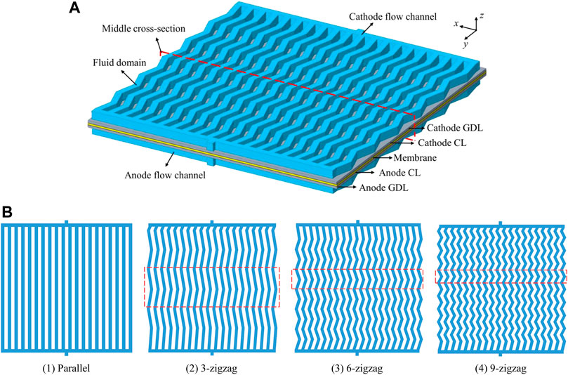
Figure 1. (A) Three-dimensional physical model of PEMFC; (B) Four different flow channel designs.

Table 1. Physical parameters and operating conditions.
To simplify the simulation processes, some assumptions are used (Kahraman and Orhan, 2017; Yin et al., 2018):
(1) PEMFC operates under steady-state and constant temperature conditions.
(2) The mixed gas is considered an incompressible ideal gas, and the gas flow is laminar in the channel.
(3) The GDL and CL are regarded as isotropic homogeneous porous materials.
(4) The contact resistance and the gravity effect are ignored.
(5) The products are assumed to be gas phase.
Based on the above-mentioned assumptions, the governing equations of continuity, momentum, components, and charge are stated as (Huang et al., 2021):
Continuity equation:
where ρ is the density of mixture and u is the velocity vector.
Momentum equation:
where ε is the porosity, p is the pressure, μ is the average viscosity of mixture, and Su is the source term.
Component equation:
where ck is the concentration of k, Sk is the component source, and Dk_eff is the effective diffusion coefficient. It can be calculated by Bruggeman’s formula (Wu, 2016) as follows:
Where Dk is the binary diffusivity, Dk_eff is the reference binary diffusivity, T is the operating temperature, T0 is the reference temperature.
Conservation of charge:
where σeff is the conductivity, the subscripts “s” and “m” are the solid phase and ionic phase, φ is the potential, S is the source term of the volume transfer current.
CL in anode:
CL in cathode:
In other regions, S = 0, where the subscripts “a” and “c” are the anode and cathode. j is the exchange current density, which can be obtained from the Butler-Volmer equation (Ozdemira and Taymaz, 2021):
where a is the electrocatalytic surface area, i0 is the exchange current density, α is the transfer coefficient, F is Faraday’s constant, R is the universal gas constant, and η is the activation overvoltage.
The working temperature and pressure of PEMFC were 453.15 K and 101 325 Pa, respectively. The walls adopted no-slip and adiabatic boundary conditions. The voltage of the anode current collector was set to 0 V and the voltage of the cathode current collector was set to the operating voltages, During the simulation process, the value of the operating voltage decreased from 0.9 to 0.4 V in 0.05 V steps. The cathode and anode inlets adopted velocity inlets, which could be calculated from Ref. (Zeng et al., 2017).
COMSOL Multiphysics commercial software was adopted to simulate the effect of different flow channel designs on the performance of PEMFC. In order to verify the accuracy of the numerical model in this paper, a comparison was carried out with the results in Ref. (Berna et al., 2016). in this paper. The geometric parameters of the PEMFC model were consistent with the reference. The operating temperature and pressure were 433 K and 120 × 103 Pa. As shown in Figure 2A, the results revealed that the numerical results were in good agreement with the experimental data, so the numerical results were considered reliable.
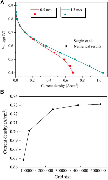
Figure 2. (A) Model validation; (B) grid independence test.
In addition, the quality of the grid also had a significant influence on the numerical results, so the grid independence analysis was carried out. The grid sizes of 742 568, 1 073 461, 2 423 520, 3 855 264, and 5 128 421 were compared, and the current density at 0.4 V was used as the monitoring object. As shown in Figure 2B, the relative deviation of the current density between 3 855 264 and 5 128 421 grids was within 0.12%. Therefore, the grid size of 3 855 264 was selected for subsequent simulation.
The effect of the zigzag flow channels on the performance was investigated in this section. As shown in Figure 3. The results revealed that there was almost no significant difference in current density for four flow channels at high voltages. This is because the activation polarization was the dominant factor at high voltages, which was mainly related to the characteristics of the membrane, and the parameters of the membrane defaulted to constants in the simulation process. As the operating voltage decreased, the current density difference among four different flow channels gradually increased. The reason is that at low operating voltages, the concentration polarization of the PEMFC was serious, and the concentration of the reactant gas had a greater influence on the performance of PEMFC. In general, the output performance of PEMFC with the zigzag flow channels was higher than that of the conventional parallel flow channel. At the operating voltage of 0.4 V, the current density of parallel, 3-zigzag, 6-zigzag, and 9-zigzag flow channels were 6885.7, 6959.7, 7165, and 7495.2 A/m2, respectively. Compared with the parallel flow channel, the current density increased by 1.07%, 4.06%, and 8.85%, indicating that a more number of turns can promote the performance of PEMFC.
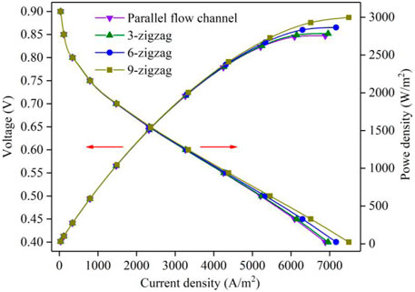
Figure 3. Polarization curves of four flow channels.
The molar concentration distribution of oxygen for different flow channels is presented in Figure 4. It can be seen that with the progress of the electrochemical reaction, the molar concentration of oxygen gradually decreased along the flow direction. In addition, the oxygen concentration in the middle channel was significantly higher than that on both sides of the flow channels, especially there were low oxygen regions at the top corner of the flow channel. It can be seen from Figures 4B–D that with the increase in the number of turns, the low oxygen concentration regions gradually decreased, which showed that the zigzag flow channels could promote the diffusion of oxygen to the interface of electrochemical reaction.
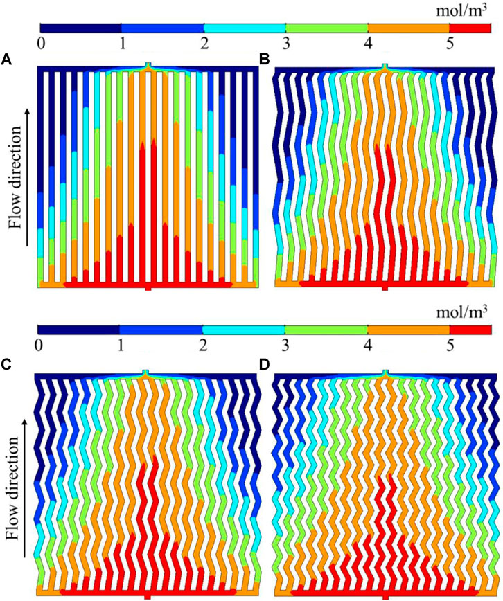
Figure 4. Molar concentration distribution of oxygen for different flow channels. (A) Parallel; (B) 3-zigzag; (C) 6-zigzag; (D) 9-zigzag.
The electrochemical reaction of PEMFC mainly takes place on the surface of CL, and the concentration distribution of oxygen on the CL directly affects the performance and stability of PEMFC. Therefore, the non-uniformity E (Liu et al., 2018) was proposed to evaluate the molar concentration distribution of oxygen on the interface between the GDL and CL at the cathode, which was defined as follows:
where x is the local concentration (mol/m3) and
Table 2 shows the oxygen non-uniformity of different flow channels. It revealed that the non-uniformity of parallel flow channels was the largest, with a value of 0.64. The oxygen non-uniformity of all zigzag flow channels was generally lower than that of the parallel flow channel, and the non-uniformity of 9-zigzag was 25.5% lower than that of parallel flow channels. For the zigzag flow channels, more number of turns results in a lower value of non-uniformity, which was beneficial to promote the output performance of PEMFC.
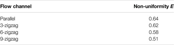
Table 2. Oxygen non-uniformity of different flow channels.
Figure 5 shows the molar concentration distribution of water in different flow channels. The results demonstrated that the molar concentration of water increased with the progress of the reaction, presenting the low molar concentration of water in the middle flow channel, and the high molar concentration on both sides. In addition, there were high water concentration regions in the corners on both sides of the top. The molar concentration of the zigzag flow channels was slightly lower than that of the parallel flow channel as a whole. It can be seen from Figure 6 that the molar concentration distribution of oxygen and water for four different flow channels was wave-like at the GDL/CL surface. The concentration distribution of water was a low concentration in the middle flow channel and a high concentration on both sides, while the concentration distribution of oxygen was the opposite. This corresponds to the contours in Figures 4, 5. It can be also seen that the molar concentration of oxygen was low in regions with a high molar concentration of water. This is because the increase in water concentration would increase the diffusion resistance of oxygen, making it more difficult for oxygen to diffuse into the CL to participate in the reaction, reducing the overall performance of PEMFC. As the number of turns increased, the molar concentration of water in the channel decreased, which showed that the zigzag flow channels could enhance the drainage effect of the parallel flow channel and improve the performance of PEMFC.
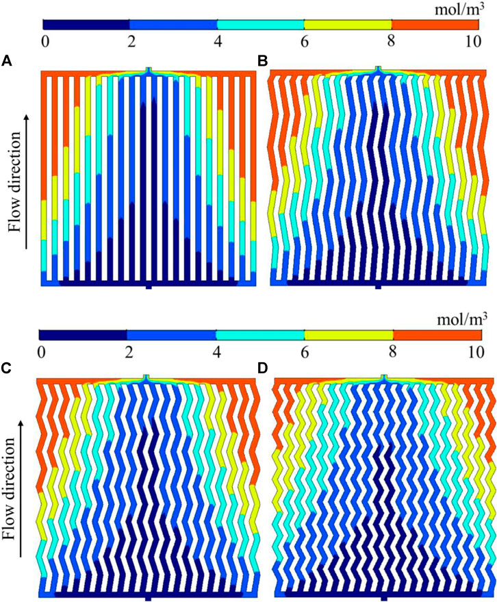
Figure 5. Molar concentration distribution of water for different flow channels. (A) Parallel; (B) 3-zigzag; (C) 6-zigzag; (D) 9-zigzag.
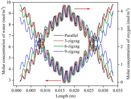
Figure 6. Molar concentration distribution of oxygen and water at GDL/CL along the channel length.
The pressure loss in the flow channels is also one of the key parameters to measure the performance of PEMFC. A large voltage drop will produce relatively large parasitic power. However, a large pressure drop can force more reaction gas to reach the CL through the GDL for reaction, and can also enhance the forced convection of water, which is beneficial to the removal of product water. The power density analysis of different flow channels is listed in Table 3. The overall pressure drop of the zigzag flow channels was larger than that of the parallel flow channel. The pressure drop of the parallel flow channel was the smallest, with a value of 243.1 Pa. 9-zigzag flow channel was 20.4 Pa higher than the parallel flow channel. It showed that as the number of turns increased, the pressure drop gradually increased, and the output power density also increased, indicating that the zigzag flow channels improved the current density of the PEMFC at the cost of increasing the pressure drop. In addition, the parasitic power also increased, but the 9-zigzag flow channel obtained the maximum net output power density due to its higher output power density.
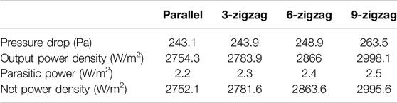
Table 3. Power density analysis of different flow channels.
The influence of zigzag flow channels on the performance of PEMFC was comprehensively quantified by the polarization curve, molar concentration of oxygen and water, and output power density. The main conclusions are as follows:
(1) The zigzag flow channels had an influence on the performance improvement of PEMFC. As the number of turns increased, the performance of PEMFC improved more significantly. Compared with the parallel channel, the maximum current density of the 3-zigzag, 6-zigzag, and 9-zigzag flow channels increased by 1.07%, 4.06%, and 8.85%, respectively.
(2) The zigzag flow channels could promote the diffusion of oxygen to the electrochemical reaction interface and improve the drainage effect. With the increase in the number of turns, the low molar concentration regions of oxygen and high molar concentration regions of water in the flow channel gradually decreased. In addition, the oxygen non-uniformity also gradually decreased. The oxygen non-uniformity in the 9-zigzag flow channel was the lowest, with a value of 0.51, which was 25.5% lower than that in the parallel flow channel.
(3) Compared with the zigzag flow channels, the pressure drop of the parallel flow channel was the lowest, with a value of 243.1 Pa. As the number of turns increased for the zigzag flow channel, the pressure drops and parasitic power density both gradually increased. The 9-zigzag flow channel obtained the maximum net power density, with a value of 2995.6 W/m2.
The original contributions presented in the study are included in the article/Supplementary Material, further inquiries can be directed to the corresponding author.
SZ and SL contributed to conception and design of the study. SZ wrote the first draft of the manuscript. HX guided the methodology, supported the fund and revised the first draft. YM and KW performed the statistical analysis and post processed the data. All authors contributed to manuscript revision, read, and approved the submitted version.
This work was financially supported by the Shanghai Natural Science Foundation (No. 20ZR1438700).
The authors declare that the research was conducted in the absence of any commercial or financial relationships that could be construed as a potential conflict of interest.
All claims expressed in this article are solely those of the authors and do not necessarily represent those of their affiliated organizations, or those of the publisher, the editors and the reviewers. Any product that may be evaluated in this article, or claim that may be made by its manufacturer, is not guaranteed or endorsed by the publisher.
Andújar, J. M., Segura, F., and Durán, E. (2011). Optimal Interface Based on Power Electronics in Distributed Generation Systems for Fuel Cells[J]. Renew. Energy 36 (11), 2759–2770.
Arasy, F., Djatmiko, I., and Fadlilatul, T. (2021). The Effect of Baffle Shape on the Performance of a Polymer Electrolyte Membrane Fuel Cell with a Biometric Flow Field[J]. Int. J. Hydrogen Energy 46 (8), 6028–6036.
Berna, S., Caglayan, D. G., and Devrim, Y. (2016). Modeling and Sensitivity Analysis of High Temperature PEM Fuel Cells by Using Comsol Multiphysics[J]. Int. J. Hydrogen Energy 41 (23), 10001–10009.
Chen, Y., Wan, Z., and Chen, X. (2021). Geometry Optimization of a Novel M-like Flow Field in a Proton Exchange Membrane Fuel Cell[J]. Energy Convers. Manag. 228, 113651.
Chowdhury, M. Z., and Akansu, Y. E. (2017). Novel Convergent-Divergent Serpentine Flow Fields Effect on PEM Fuel Cell Performance. Int. J. Hydrogen Energy 42 (40), 25686–25694. doi:10.1016/j.ijhydene.2017.04.079
Emine, Ö., Ayşenur, Ö., and Yurtcan, A. B. (2020). Utilization of the Graphene Aerogel as PEM Fuel Cell Catalyst Support: Effect of Polypyrrole (PPy) and Polydimethylsiloxane (PDMS) Addition[J]. Int. J. Hydrogen Energy 45 (60), 34818–34836.
Gómez, J. C., Serra, M., and Attila, H. (2021). Controller Design for Polymer Electrolyte Membrane Fuel Cell Systems for Automotive Applications[J]. Int. J. Hydrogen Energy 46 (45), 23263–23278.
Huang, H., Liu, M., Li, X., Guo, X., Wang, T., Li, S., et al. (2022). Numerical Simulation and Visualization Study of a New Tapered-Slope Serpentine Flow Field in Proton Exchange Membrane Fuel Cell. Energy 246, 123406. doi:10.1016/j.energy.2022.123406
Huang, T., Wang, W., Yuan, Y., Huang, J., Chen, X., Zhang, J., et al. (2021). Optimization of High-Temperature Proton Exchange Membrane Fuel Cell Flow Channel Based on Genetic Algorithm. Energy Rep. 7, 1374–1384. doi:10.1016/j.egyr.2021.02.062
Kahraman, H., and Orhan, M. F. (2017). Flow Field Bipolar Plates in a Proton Exchange Membrane Fuel Cell: Analysis & Modeling. Energy Convers. Manag. 133, 363–384. doi:10.1016/j.enconman.2016.10.053
Liao, Z., Wei, L., Dafalla, A. M., Guo, J., and Jiang, F. (2021). Analysis of the Impact of Flow Field Arrangement on the Performance of PEMFC with Zigzag-Shaped Channels. Int. J. Heat Mass Transf. 181, 121900. doi:10.1016/j.ijheatmasstransfer.2021.121900
Liao, Z., Wei, L., Dafalla, A. M., Suo, Z., and Jiang, F. (2021). Numerical Study of Subfreezing Temperature Cold Start of Proton Exchange Membrane Fuel Cells with Zigzag-Channeled Flow Field. Int. J. Heat Mass Transf. 165, 120733. doi:10.1016/j.ijheatmasstransfer.2020.120733
Liu, H., Yang, W., Tan, J., An, Y., and Cheng, L. (2018). Numerical Analysis of Parallel Flow Fields Improved by Micro-distributor in Proton Exchange Membrane Fuel Cells. Energy Convers. Manag. 176, 99–109. doi:10.1016/j.enconman.2018.09.024
Ozdemira, S. N., and Taymaz, I. (2021). Numerical Investigation of the Effect of Blocked Gas Flow Field on PEM Fuel Cell Performance. Int. J. Environ. Sci. Technol. 18 (11), 3581–3596. doi:10.1007/s13762-020-03075-3
Pahon, E., Bouquain, D., Hissel, D., Rouet, A., and Vacquier, C. (2021). Performance Analysis of Proton Exchange Membrane Fuel Cell in Automotive Applications. J. Power Sources 510, 230385. doi:10.1016/j.jpowsour.2021.230385
Qian, L., Li, X., and Zhang, S. (2022). Novel Sulfonated N-Heterocyclic Poly(aryl Ether Ketone Ketone)s with Pendant Phenyl Groups for Proton Exchange Membrane Performing Enhanced Oxidative Stability and Excellent Fuel Cell Properties[J]. J. Membr. Sci. 641, 119926.
Rivarolo, M., Rattazzi, D., Lamberti, T., and Magistri, L. (2020). Clean Energy Production by PEM Fuel Cells on Tourist Ships: A Time-dependent Analysis. Int. J. Hydrogen Energy 45 (47), 25747–25757. doi:10.1016/j.ijhydene.2019.12.086
Sadhasivam, T., and Oh, T. H. (2021). Progress in Poly(phenylene Oxide) Based Cation Exchange Membranes for Fuel Cells and Redox Flow Batteries Applications[J]. Int. J. Hydrogen Energy 46 (77), 38381–38415.
Samaneh, S., and Jean, H. (2015). Improved Carbon Nanostructures as a Novel Catalyst Support in the Cathode Side of PEMFC: a Critical Review[J]. Carbon 94, 705–728.
Selvaraj, A. S., and Rajagopal Thundil Karuppa, R. (2019). Effect of Flow Fields and Humidification of Reactant and Oxidant on the Performance of Scaled-Up PEM-FC Using CFD Code[J]. Int. J. Energy Res. 43 (13), 7254–7274.
Seyed Ali, A., and Ebrahim, A. (2019). Three-dimensional Multiphase Model of Proton Exchange Membrane Fuel Cell with Honeycomb Flow Field at the Cathode Side[J]. J. Clean. Prod. 214, 738–748.
Seyhan, M., Akansu, Y. E., Murat, M., Korkmaz, Y., and Akansu, S. O. (2017). Performance Prediction of PEM Fuel Cell with Wavy Serpentine Flow Channel by Using Artificial Neural Network. Int. J. Hydrogen Energy 42 (40), 25619–25629. doi:10.1016/j.ijhydene.2017.04.001
Shiang-Wuu, P., Wu, H. W., and Chen, Y. B. (2019). Performance Enhancement of a High Temperature Proton Exchange Membrane Fuel Cell by Bottomed-Baffles in Bipolar-Plate Channels[J]. Appl. Energy 255, 113815.
Stempien, J. P., and Chan, S. H. (2017). Comparative Study of Fuel Cell, Battery and Hybrid Buses for Renewable Energy Constrained Areas. J. Power Sources 340, 347–355. doi:10.1016/j.jpowsour.2016.11.089
Wang, J. (2015). Barriers of Scaling-Up Fuel Cells: Cost, Durability and Reliability. Energy 80, 509–521. doi:10.1016/j.energy.2014.12.007
Wang, J. (2017). System Integration, Durability and Reliability of Fuel Cells: Challenges and Solutions. Appl. Energy 189, 460–479. doi:10.1016/j.apenergy.2016.12.083
Wang, X., Qin, Y., Wu, S., Shangguan, X., Zhang, J., and Yin, Y. (2020). Numerical and Experimental Investigation of Baffle Plate Arrangement on Proton Exchange Membrane Fuel Cell Performance. J. Power Sources 457, 228034. doi:10.1016/j.jpowsour.2020.228034
Wu, H. W. (2016). A Review of Recent Development: Transport and Performance Modeling of PEM Fuel Cells. Appl. Energy 165, 81–106. doi:10.1016/j.apenergy.2015.12.075
Yin, Y., Wang, X., Shangguan, X., Zhang, J., and Qin, Y. (2018). Numerical Investigation on the Characteristics of Mass Transport and Performance of PEMFC with Baffle Plates Installed in the Flow Channel. Int. J. Hydrogen Energy 43 (16), 8048–8062. doi:10.1016/j.ijhydene.2018.03.037
Zeng, X., Ge, Y., Shen, J., Zeng, L., Liu, Z., and Liu, W. (2017). The Optimization of Channels for a Proton Exchange Membrane Fuel Cell Applying Genetic Algorithm. Int. J. Heat Mass Transf. 105, 81–89. doi:10.1016/j.ijheatmasstransfer.2016.09.068
Keywords: proton exchange membrane fuel cell, zigzag flow channel, numerical modeling, performance improvement, structural optimization
Citation: Zhang S, Liu S, Xu H, Mao Y and Wang K (2022) Numerical Investigation on the Performance of Proton Exchange Membrane Fuel Cell With Zigzag Flow Channels. Front. Therm. Eng. 2:907873. doi: 10.3389/fther.2022.907873
Received: 30 March 2022; Accepted: 20 April 2022;
Published: 10 May 2022.
Edited by:
Zhiguo Qu, Xi’an Jiaotong University, ChinaReviewed by:
Li Chen, Xi’an Jiaotong University, ChinaCopyright © 2022 Zhang, Liu, Xu, Mao and Wang. This is an open-access article distributed under the terms of the Creative Commons Attribution License (CC BY). The use, distribution or reproduction in other forums is permitted, provided the original author(s) and the copyright owner(s) are credited and that the original publication in this journal is cited, in accordance with accepted academic practice. No use, distribution or reproduction is permitted which does not comply with these terms.
*Correspondence: Hongtao Xu, aHR4dUB1c3N0LmVkdS5jbg==
Disclaimer: All claims expressed in this article are solely those of the authors and do not necessarily represent those of their affiliated organizations, or those of the publisher, the editors and the reviewers. Any product that may be evaluated in this article or claim that may be made by its manufacturer is not guaranteed or endorsed by the publisher.
Research integrity at Frontiers
Learn more about the work of our research integrity team to safeguard the quality of each article we publish.