 Zixuan Wang1Linhao Fan1Siyuan Wu2Chasen Tongsh1Yanyi Zhang3
 Zirong Yang3Qing Du1Dong Hao3*Feikun Zhou4*
 Kui Jiao1*
- 1State Key Laboratory of Engines, Tianjin University, Tianjin, China
- 2Department of Mechanical and Aerospace Engineering, University of California, Davis, Davis, CA, United States
- 3China Automotive Technology and Research Center Co., Ltd., Tianjin, China
- 4Foshan Xianhu Laboratory of the Advanced Energy Science and Technology Guangdong Laboratory, Xianhu Hydrogen Valley, Foshan, China
Using metal foam as a flow field structure is an attractive route to improve the performance of open-cathode PEMFC. Metal foam has shown great potential in improving the uniformity of reactants, but optimized structure parameters that can more effectively transfer gas and remove excess water are needed. Here we experimentally investigate the effect of metal foam structure parameters on cell performance using polarization curves, power density curves, and electrochemical impedance spectrum (EIS) measurements. By optimizing the pore density, thickness, and compression ratio of the metal foam, the performance of the fuel cell is improved by 49.8%, 42.1%, and 7.3%, respectively. The optimum structure value of metal foam is the pore density of 40 PPI, the thickness of 2.4 mm, and the compression ratio of 4:2.4. In this configuration, the cell could achieve a maximum power density of 0.485 W cm−2. The findings of this work are beneficial for the application of metal foams in open-cathode PEMFC.
Introduction
Proton exchange membrane fuel cells (PEMFCs) have been receiving worldwide attention due to the increasingly serious problem of environmental pollution and the depletion of traditional fossil fuels (Wang et al., 2020; Jiao et al., 2021). It releases energy through electrochemical reactions of oxygen and hydrogen (Ding et al., 2021; Chen et al., 2022). Especially, open-cathode PEMFCs generally operate with lower parasitic power and simple structure, widely used in a broad range of small-scale applications such as unmanned aerial vehicles (UAVs), auxiliary power units (APUs), and portable applications. In general, the open-cathode PEMFCs using air as coolant and oxidant have lower performance than traditional liquid-cooled PEMFCs due to their lower oxygen partial pressure and air humidification. Optimization of the transport of reactants and removal of products is a key factor in enhancing cell performance (Gu et al., 2021; Yang et al., 2022). To achieve this, it is crucial to optimize the flow-field design of bipolar plates due to their function in reactants distribution and products removal.
The parallel flow field is one of the most common flow field patterns used in open-cathode PEMFC due to its simple structure, easy processing, and excellent heat dissipation. Several studies have focused on optimizing the performance of open-cathode PEMFCs with parallel flow field designs, including channel width (Kim et al., 2013; Qiu et al., 2020; Zhao et al., 2020), depth (Zhao et al., 2020), the rib-channel ratio (Kiattamrong and Sripakagorn, 2015), and length-width ratios (Zhao et al., 2021). Unfortunately, parallel flow fields are associated with several issues due to their typical rib-channel structure, such as non-uniform gas distribution and liquid accumulation under ribs (Jiao and Li, 2011), which exacerbate the uneven electrochemical reaction then reduce the durability of the open-cathode PEMFC.
Recently metal foam flow field with a three-dimensional porous structure has good gas distribution properties and gas permeability (Kang et al., 2020a; Bao et al., 2020), which could be introduced to PEMFC to enhance cell performance. Bao et al. (2020) simulated the two-phase flow behavior of the metal foam flow field using a volume of fluid (VOF) method. They found that the metal foam flow field exhibited excellent performance at high-current-density operation conditions for PEMFC. Liu et al. (2020) experimentally optimized the operating parameters of fuel cells using metal foam flow fields and improved the power output performance of fuel cells. Furthermore, Wan et al. (2021) carried out a series of experiments to compare the effects of metal foam flow fields placed at the cathode and anode of the fuel cells. They concluded that the use of metal foam on the cathode side of the fuel cell is prone to flooding, especially under high relative humidity conditions.
At present, many researchers have conducted experiments and models on open-cathode PEMFC with metal foam flow fields. A. Baroutaji et al. (2017) applied the metal foam to the anode and cathode side of open-cathode PEMFC and tested it. They found that the metal foam could provide better gas distribution than conventional flow plates and exhibit better performance. Mohammad et al. (Sajid Hossain and Shabani, 2019) compared the performance of metal foams used as cathode flow fields in open-cathode and closed-cathode PEMFCs with an active area of 225 cm2. Their results showed that the closed-cathode PEMFCs showed a better performance than the open-cathode PEMFCs. Kang et al. (2020b) conducted both experiments and theoretical studies to investigate the metal foam inserted in the cathode side of open-cathode PEMFC. They reported that the use of metal foam in open-cathode PEMFC could solve the problems of membrane dehydration and poor air delivery. Lee et al. (2021) also used metal foam as the cathode flow field of open-cathode PEMFC. They proposed that the use of metal foam leads to the larger power consumption of the parasitic fan because the pressure drop of the metal foam flow field is about three times higher than that of the parallel flow field. Meanwhile, Wang et al. (2022) compared the cell performance of the metal foam flow field with that of the parallel flow field and the pin-type flow field. Combining the electrochemical impedance spectrum (EIS) data, they concluded that the metal foam flow field could better reduce the mass transfer loss of the open-cathode PEMFC. They also found that the metal foam flow field exhibited poorer heat dispersing characteristics than the parallel flow field under the same fan power condition.
From reviewing experiments and models with metal foam as a flow field in open-cathode PEMFC, limited research on the effect of metal foam structure parameters on the open-cathode PEMFC performance has been cited. Although metal foam flow fields could enhance the uniformity of gas distribution, a significant disadvantage of metal foam flow field designs compared with other flow field designs is that they have a higher flow resistance, which results in a larger pressure drop. Therefore, it is important to optimize the metal foam structure parameters to improve the performance of open-cathode PEMFC. In this study, metal foams with different structure parameters (pore density, thickness, compression ratio) are applied to an open-cathode PEMFC as the cathode flow field. Polarization curves, power density curves, and EIS measurements are used to analyze the cell performance and internal losses.
Experiments
Experimental Setup
In this study, an open-cathode PEMFC is designed and tested, as shown in Figure 1A. The commercially available membrane electrode assembly (MEA) used in the experiments has an active cell area of 7 cm2 and the platinum loading in the anode and cathode is 0.07 and 0.3 mg cm−2, respectively. The serpentine flow field made of graphite is designed in the anode for all experiments, the width of the channel and rib is 1.0 mm. And the metal foam flow field is used on the cathode side. The 3D schematic of open-cathode PEMFC is shown in Figure 1B.
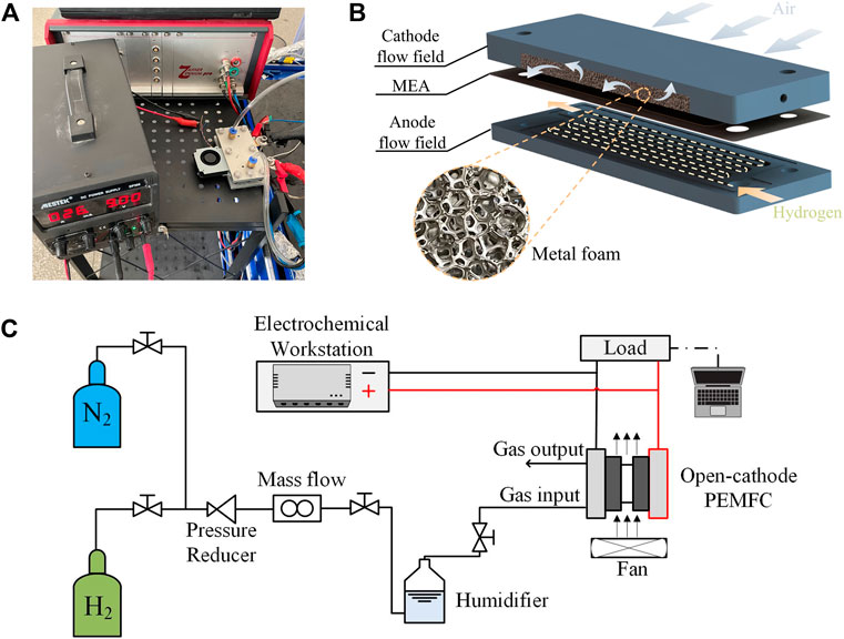
Figure 1. Schematic diagram of the experimental setup. (A) Experimental setup. (B) 3D schematic of open-cathode PEMFC. (C) Schematic diagram of the experimental setup.
A schematic diagram of the experimental setup is shown in Figure 1C. A test system (PEM400W) purchased from the company Ningbo Beit Technology is used to perform polarization tests. All test experiments use ultra-high purity (99.999%) hydrogen and nitrogen gas. An additional air fan (BSB0512LAA01, Delta Electronics Industrial Co.,Ltd.) located at the edge of the cathode flow field is powered by a digitally adjustable DC power supply (DP305, MESTEK) to ensure the air supply to the cathode. In addition, electrochemical impedance spectroscopy (EIS) is performed to measure the cell resistance using an electrochemical workstation (Zennium pro, German).
Metal Foam Design
The metal foam used in this experiment is made of nickel, with a porosity of 97%. To obtain the required flow field size, the metal foam is cut to a size of 50 mm × 23 mm. At the same time, the metal foam needs to be compressed to the set thickness of the flow field. According to the definition by Kim (Kim et al., 2018), the porosity after compression is calculated as follows:
where
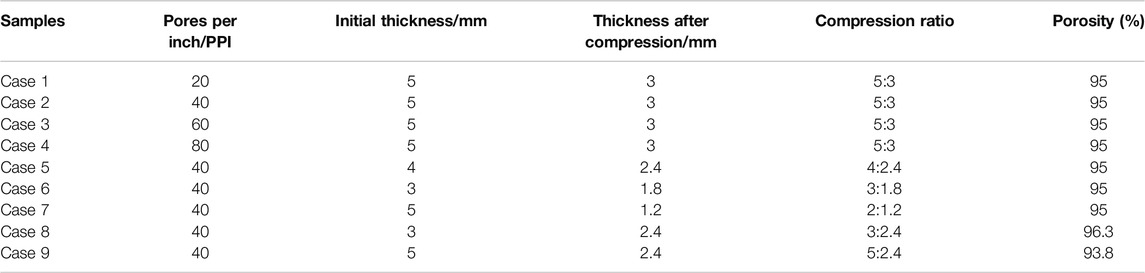
Table 1. Specification of metal foam flow fields.
Experimental Procedure
All experiments are conducted after the fuel cell are fully activated. In the tested process, 90 standard cubic centimeters per minute (sccm) of completely humidified hydrogen is supplied. The fan power voltage and current are 9 V and 26 mA, respectively. Polarization curves are conducted in galvanostatic mode (0–1 A cm−2) at an interval of 0.1 A cm−2, every single current density point tested sustains at least 2 mins. EIS is measured at a current density of 0.2 and 0.8 A cm−2, respectively. During all EIS measurements, the sweeping frequencies are in the range of 0.1 Hz–100 kHz, and the amplitude of the alternating current is 5%–10% of the direct current. It is worth noting that the MEA will be replaced with a new one before the next set of experiments to ensure accuracy and to avoid degradation of cell performance due to metal foam damaging the MEA structure. Additionally, Table 2 summarizes the details of experimental conditions.
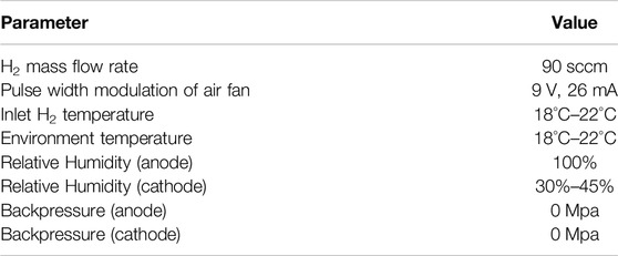
Table 2. Experimental conditions.
Results
Effect of Metal Foam Pore Density
In general, pores per inch (PPI) is used to quantify the pore density of metal foams. For metal foams, the effective diameter of the average pore decreases with increasing PPI, and the pore density increases with increasing PPI. The variations of metal foam pore density significantly impact the management of water and gas in open-cathode PEMFC. In this section, the effect of metal foam pore density on the open-cathode PEMFC performance is investigated by adjusting the metal foam pore density of 20, 40, 60, and 80 PPI. The thickness and compression ratio of the metal foam flow field are set to be 3 mm and 5:3, respectively.
As the metal foam pore density increases, on the one hand, the flow path becomes more complicated and tortuous in the metal foam structure, thus the flow resistance increases; on the other hand, fewer reactants flow through the pores to the reaction zone due to the reduced permeability of the metal foam, which reduces the flow resistance and is bad for the cell performance. The cell performances for different metal foam pore densities are compared and the results are shown in Figures 2A,B. When the current density is less than 0.2 A cm−2, the pore density change of metal foam has little effect on the cell performance. However, the performances of the cell appear significant difference at different metal foam pore densities when the density is more than 0.2 A cm−2. As a whole, it can be seen that the cell performance shows a trend of increasing first and then decreasing as the metal foam pore density increases, reaching its best performance at 40 PPI. Further, the decreasing trend of cell performance speeded up gradually when the metal foam pore density exceeds 40 PPI. This tendency mainly corresponds to the change in pressure drop which is positively related to the flow resistance. The results demonstrate that the enhanced diffusion of the gas is dominant until the pressure drop reaches its peak value, thus the cell performance increases. After that, the reduction of reactants flowing into the reaction zone will cause a decreased pressure drop, which can significantly decrease the performance of the fuel cell. Similar conclusions are experimentally obtained by Liu et al. (2015). However, in the open-cathode PEMFC, the pressure drop could not increase too much due to the low oxygen partial pressure provided by a DC fan; instead, the decrease in reactants entering the fuel cell will worsen the cell performance, especially the pore density is beyond 40 PPI. Therefore, the cell performance would begin to decline when the pore density is beyond 40 PPI. Among four metal foams, 40 PPI shows the highest maximum power of the fuel cell in this experiment, and the maximum power density is 0.493 W cm−2. The cell showed the worst performance at a metal foam pore density of 20 PPI, with a maximum power density of 0.329 W cm−2.
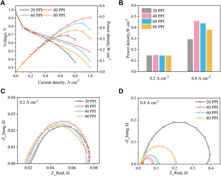
Figure 2. Compared different metal foam pore densities (A) Polarization and power density curves (B) Power density at 0.2 A cm−2 and 0.8 A cm−2 (C) EIS at 0.2 A cm−2 (D) EIS at 0.8 A cm−2.
The EIS is tested at both 0.2 and 0.8 A cm−2 to compare the electrochemical impedance of the fuel cell under different metal foam pore densities, and the Nyquist plots are presented in Figures 2C,D. In the Nyquist plot, the high-frequency intercept of the impedance arc on the real axis represents the total ohmic resistance of the cell, which includes the contact resistance between components and the ohmic resistance of the cell (Yuan et al., 2007). The diameter of the kinetic loop reflects the sum of the charge transfer and mass transfer resistances. As illustrated in Figure 2C, the metal foam pore density has little influence on the total impendence of the cell at the current density of 0.2 A cm−2. However, it can be seen that the ohmic resistance decreases with the increase of metal foam pore density. This is because the metal foam with low pore density is easier to cause the decline of the membrane hydration level in the low current density region. As the pore density decreases, the pore size and airflow rate increase, which allows more of the product water to be carried away by the air, thus increasing the ohmic resistance. As shown in Figure 2D, the ohmic resistance has no significant difference at 0.8 A cm−2, since the fact that the product water is sufficient to wet the MEA at a high current density region and ensure a good conductivity of the membrane, so the ohmic resistance of four cases is almost the same. Especially, the cell with 20 PPI metal foam has the largest charge transfer and mass transfer resistances. The reason is that the 20 PPI metal foam has the largest ligament diameter, resulting in product water being trapped in the ligament intersection area and suppressing the gas diffusion. As metal foam pore density is higher than 20 PPI, it is interesting to find that the charge transfer and mass transfer resistances experience a significant reduction. The main reasons are that the negative effect of increasing the metal foam pore density is weak, and the increased pressure drop increases the uniformity of gas distribution and the mass transfer rate of air to the gas diffusion layer (GDL). In addition, the diameter of the kinetic loop continues to increase when the metal foam pore density exceeds 40 PPI, which is also a validation that the decrease in reactants flowing in the foam region leads to reduce the cell performance.
Effect of Metal Foam Thickness
Since the metal foam thickness plays a significant role in the gas transportation and water management of open-cathode PEMFC. In this section, the metal foams with different thicknesses (3, 2.4, 1.8, and 1.2 mm) are applied in open-cathode PEMFC to investigate the effect of metal foam thickness on cell performance. For all metal foams used in this section, the metal foam pore density is 40 PPI and the compression ratio is set to a constant value (5:3).
Figure 3A illustrates the polarization curves and power curves of the cell with different metal foam thicknesses. It is shown that the cell performance has significant improvement with the increase of the metal foam thickness. The reason is that as the thickness of the metal foam increases, more air enters the foam area to participate in the electrochemical reaction, thus increasing the cell performance. However, these patterns also show that the amplitude of the cell performance increment is decreased with the increase of the metal foam thickness until the cell performance stabilizes. This tendency is similar to the results of the effect of gas flow rate on the cell performance with meal foam flow field in Wang et al. (2022), which also verifies the above explanation. The cell with 3 mm thickness metal foam still shows the highest maximum power of the fuel cell in this experiment as well, as shown in Figure 3B.
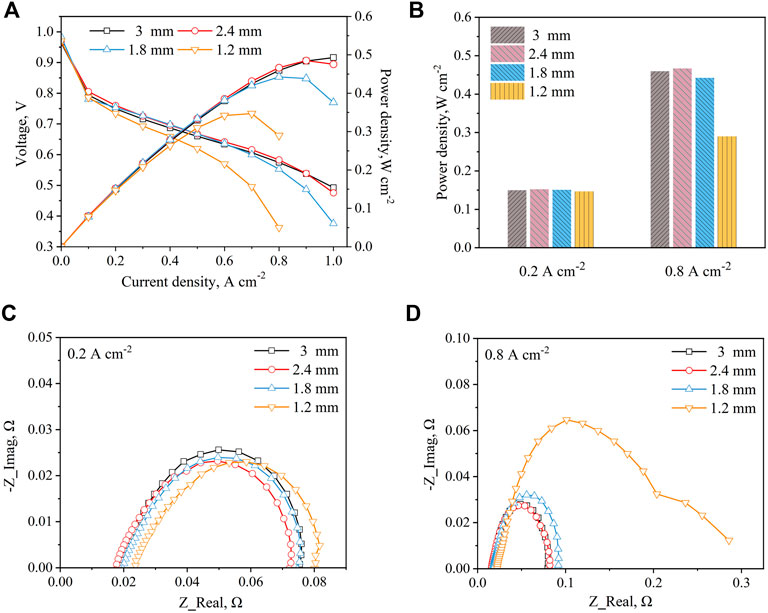
Figure 3. Compared different metal foam thickness (A) Polarization and power density curves (B) Power density at 0.2 A cm−2 and 0.8 A cm−2 (C) EIS at 0.2 A cm−2 (D) EIS at 0.8 A cm−2.
EIS measurements of the fuel cell under metal foam with different thicknesses are demonstrated in Figures 3C,D. As shown in Figure 3C, the charge transfer and mass transfer resistances of these four samples remain almost the same at the current density of 0.2 A cm−2. This means that the charge transfer and mass transfer resistances cannot change significantly as the thickness of the metal foam increases due to the amount of air entering the cell being sufficient. Especially, the main difference is in the ohmic resistance, which decreases and stabilizes as the thickness of the metal foam increases. In general, the resistance of metal foam is positively related to its thickness. However, as the mechanical strength of the metal foam increases with thickness, the contact resistance decreases due to the contact stress increases between the metal foam and the cell. The EIS results demonstrate that the influence of contact resistance is dominant before the contact stress reaches the peak value, thus the cell ohmic resistance decreases with the thickness of the metal foam. After that, the resistance of metal foam is dominant, thus the ohmic resistance increases. According to Figure 3D, when the thickness of metal foam reaches 1.2 mm, the charge transfer and mass transfer resistances of the cell have a significant improvement with the decrease of the meatal foam thickness. As analyzed above, it is because that limited air is difficult to remove excessive product water, which blocks gas transfer to MEA.
Effect of Compression Ratio
To improve the mechanical strength and conductivity, metal foam needs to be compressed to an appropriate thickness of the flow field. In this section, the metal foams with different compression ratios (5:2.4, 4:2.4, 3:2.4) are tested to explore the effect of cell performance. The thickness of metal foam is fixed at 2.4 mm and pore density is set to 40 PPI.
In Figure 4A, the cell performance firstly increases and then decreases with the increase of the compression ratio. Because as the compression ratio increases, on the one hand, the metal foam porosity decreases, which causes an increase in gas diffusion and improves the cell performance; on the other hand, the volume of the metal foam skeleton increases, which leads to the decrease of the amount of air entering the metal foam region and a decrease in cell performance. At the same time, the change of resistance caused by the thickness of metal foam will also affect cell performance. These results indicate that there is an optimal value of performance as the compression ratio increases due to the simultaneous influence of several aspects on the cell performance. However, in this experiment, a better compression ratio suitable for our experiments is obtained due to there being a limitation on the metal foam available commercially. As shown in Figure 4B, the cell with the compression ratio of 4:2.4 has the highest power density at the current density of 0.8 A cm−2, and the cell with a compression ratio of 5:2.4 and 3:2.4 shows a similar performance.
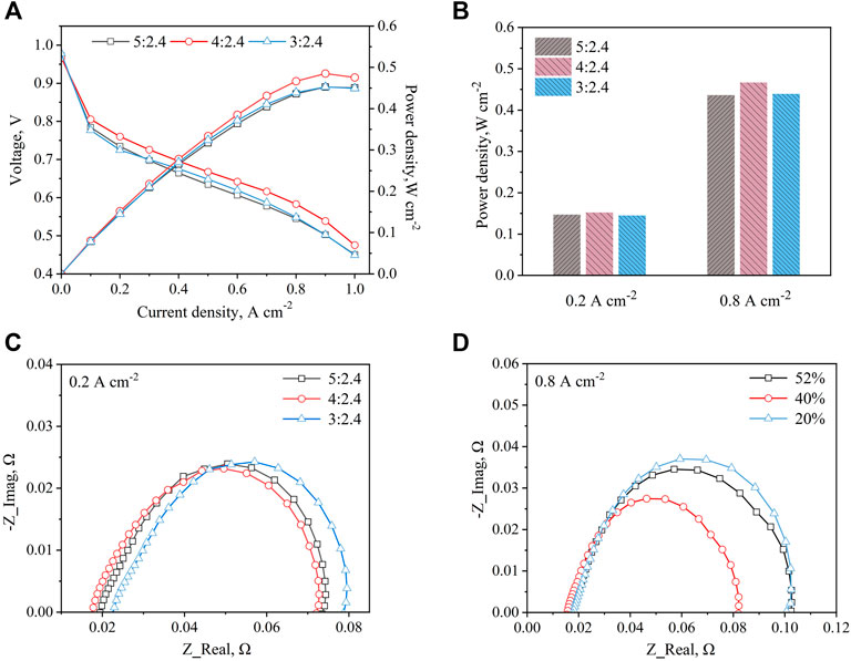
Figure 4. Compared different metal foam compression ratios (A) Polarization and power density curves (B) Power density at 0.2 A cm−2 and 0.8 A cm−2 (C) EIS at 0.2 A cm−2 (D) EIS at 0.8 A cm−2.
Figure 4C reveals the EIS results of the cell with different metal foam compression ratios at the current density of 0.2 A cm−2. It can be seen that with the increase of the compression ratio, the charge transfer and mass transfer resistances show similar values, but the ohmic resistance shows a tendency to decrease and then increase. This is because as the compression ratio of the foam metal increases, the mechanical properties, and electrical conductivity increase, and therefore the ohmic resistance decreases. However, as the compression ratio increases further, the initial thickness of the metal foam increases, which in turn increases the ohmic resistance. In Figure 4D, the cell with a metal foam compression ratio of 4:2.4 shows the lowest charge transfer and mass transfer resistances. This result verifies that although increasing the compression ratio of metal foam can increase the complexity of gas flow paths, increase the uniformity of gas distribution and thus reduce its charge transfer and mass transfer resistances, the reduction in the amount of air entering the cell due to the compression of metal foam will make it difficult to remove the product water and increase the charge transfer and mass transfer resistance.
Discussions
Figure 5 summarizes the maximum power density of all cases. As can be seen that the maximum power density of the cell is 0.493 W cm−2 when the pore density, thickness, and compression ratio of the metal foam are 40 PPI, 3 mm, and 5:3, respectively. Especially, the most important factor affecting the cell performance is the pore density of the metal foam, and the maximum power density is improved by 49.8% by optimizing the pore density. Despite the reduction in reactants flowing into the reaction zone due to the increase in thickness and pore density, the cell with 40 PPI pore density and 1.8 mm thickness of metal foam exhibits a similar maximum power density as the cell with 60 PPI pore density and 3 mm thickness of the metal foam, at the same compression ratio. Similarly, the thickness of metal foam has a significant impact on cell performance. By optimizing the thickness of the metal foam, the maximum power density of the fuel cell is increased by 42.1%. At the same compression ratio and pore density of the metal foam, the cell with metal foam of 2.4 mm thickness shows similar maximum output performance as the cell with metal foam of 3 mm thickness. However, since the increase in thickness brings an increase in cell size and mass, the metal foam with a 2.4 mm thickness is more appropriate. Additionally, the compression ratio of metal foam has the least impact on cell performance compared to the other two factors. Optimizing the compression ratio of the metal foam contributes to a 7.3% cell performance improvement. As a result, to obtain a higher cell performance, the optimal structure of the metal foam is a pore density of 40 PPI, a thickness of 2.4 mm, and a compression ratio of 40%.
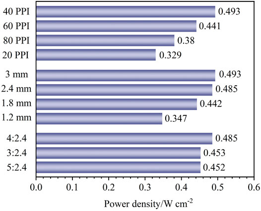
Figure 5. Summary of maximum power density for different cases.
Conclusion
In this paper, aiming at improving the open-cathode PEMFC performance with metal foam flow field, the meatal foams with different structure parameters are experimentally studied. Polarization curves, power density curves, and EIS measurements are carried out to search for a better metal foam design for open-cathode PEMFC. Detailed conclusions are as follows:
1. The pore density of the metal foam is a vital factor in cell performance. The analysis revealed that as the metal foam pore density increases, the cell performance increases firstly due to the increased pressure drop and then decreases for the reduction of reactants flowing into the reaction zone. The maximum power density is improved by 49.8% by optimizing the pore density.
2. Increasing the thickness of the metal foam can improve the performance of the fuel cell. It is worth noting that the amplitude of the cell performance increment is decreased with the increase of the metal foam thickness until the cell performance stabilizes. By optimizing the thickness of the metal foam, the maximum power density of the fuel cell is increased by 42.1%.
3. The compression ratio of the metal foam has little effect on the performance of the cell. Increasing in compression ratio slightly will increase the cell performance, but a further increase in the compression ratio of the metal foam will have a negative effect on cell performance. Optimization of the compression ratio of metal foam results in a 7.3% increase in cell performance.
The above findings demonstrate that the structural parameters of the metal foam are critical to the performance of open-cathode PEMFC. Synthesize the experimental results of this study, the optimal structure of the metal foam is a pore density of 40 PPI, a thickness of 2.4 mm, and a compression ratio of 4:2.4. The cell performance has been enhanced by optimizing the structural parameters of the metal foam, which makes the metal foam a promising flow field for future open-cathode PEMFC.
Data Availability Statement
The original contributions presented in the study are included in the article/supplementary material, further inquiries can be directed to the corresponding authors.
Author Contributions
ZW: Experiments, Writing—original draft. LF: Methodology, Validation. SW: Methodology, Experiments. CT: Data Curation. YZ: Project administration. ZY: Investigation. QD: Investigation. DH and FZ: Conceptualization, Formal analysis, Writing—Review & editing. KJ: Supervision, Conceptualization, Funding acquisition, Writing—Review & editing.
Funding
This research is funded by the National Natural Science Foundation of China (No.51920105010), the National Natural Science Foundation of Tianjin (China) for Distinguished Young Scholars (No.18JCJQJC46700), and the Tianjin Research Innovation Project for Postgraduate Students (No.2021YJSB127).
Conflict of Interest
Authors YZ, ZY, and DH were employed by China Automotive Technology and Research Center Co., Ltd.
The remaining authors declare that the research was conducted in the absence of any commercial or financial relationships that could be construed as a potential conflict of interest.
The authors declare that they have no known competing financial interests or personal relationships that could have appeared to influence the work reported in this paper.
Publisher’s Note
All claims expressed in this article are solely those of the authors and do not necessarily represent those of their affiliated organizations, or those of the publisher, the editors and the reviewers. Any product that may be evaluated in this article, or claim that may be made by its manufacturer, is not guaranteed or endorsed by the publisher.
References
Bao, Z., Niu, Z., and Jiao, K. (2020). Gas Distribution and Droplet Removal of Metal Foam Flow Field for Proton Exchange Membrane Fuel Cells. Appl. Energy 280, 116011. doi:10.1016/j.apenergy.2020.116011
Baroutaji, A., Carton, J. G., Stokes, J., and Olabi, A. G. (2017). Application of Open Pore Cellular Foam for Air Breathing PEM Fuel Cell. Int. J. Hydrogen Energy 42, 25630–25638. doi:10.1016/j.ijhydene.2017.05.114
Chen, H., Guo, H., Ye, F., and Ma, C. F. (2022). Diffusive and Convective Mass Transportations in Proton Exchange Membrane Fuel Cells with Orientational Flow Channels Having Porous Blocks. Int. J. Green Energy, 1–10. doi:10.1080/15435075.2022.2038612
Ding, R., Yin, W., Cheng, G., Chen, Y., Wang, J., Wang, R., et al. (2021). Boosting the Optimization of Membrane Electrode Assembly in Proton Exchange Membrane Fuel Cells Guided by Explainable Artificial Intelligence. Energy AI 5, 100098. doi:10.1016/j.egyai.2021.100098
Gu, X., Hou, Z., and Cai, J. (2021). Data-based Flooding Fault Diagnosis of Proton Exchange Membrane Fuel Cell Systems Using LSTM Networks. Energy AI 4, 100056. doi:10.1016/j.egyai.2021.100056
Jiao, K., and Li, X. (2011). Water Transport in Polymer Electrolyte Membrane Fuel Cells. Prog. Energy Combust. Sci. 37, 221–291. doi:10.1016/j.pecs.2010.06.002
Jiao, K., Wang, B., Du, Q., Wang, Y., Zhang, G., Yang, Z., et al. (2021). “Chapter 1 - Introduction,” in Water and Thermal Management of Proton Exchange Membrane Fuel Cells. Editors K. JIAO, B. WANG, Q. DU, Y. WANG, G. ZHANG, Z. YANGet al. (Elsevier).
Kang, D. G., Lee, D. K., Choi, J. M., Shin, D. K., and Kim, M. S. (2020a). Study on the Metal Foam Flow Field with Porosity Gradient in the Polymer Electrolyte Membrane Fuel Cell. Renew. Energy 156, 931–941. doi:10.1016/j.renene.2020.04.142
Kang, D. G., Park, C., Lim, I. S., Choi, S. H., Lee, D. K., and Kim, M. S. (2020b). Performance Enhancement of Air-Cooled Open Cathode Polymer Electrolyte Membrane Fuel Cell with Inserting Metal Foam in the Cathode Side. Int. J. Hydrogen Energy 45, 27622–27631. doi:10.1016/j.ijhydene.2020.07.102
Kiattamrong, S., and Sripakagorn, A. (2015). Effects of the Geometry of the Air Flowfield on the Performance of an Open-Cathode PEMFC - Transient Load Operation. Energy Procedia 79, 612–619. doi:10.1016/j.egypro.2015.11.541
Kim, B., Lee, Y., Woo, A., and Kim, Y. (2013). Effects of Cathode Channel Size and Operating Conditions on the Performance of Air-Blowing PEMFCs. Appl. Energy 111, 441–448. doi:10.1016/j.apenergy.2013.04.091
Kim, M., Kim, C., and Sohn, Y. (2018). Application of Metal Foam as a Flow Field for PEM Fuel Cell Stack. Fuel Cells 18, 123–128. doi:10.1002/fuce.201700180
Lee, N., Salihi, H., Yoo, B., Lee, J., Lee, S. W., Jang, S. S., et al. (2021). Metal-foam-based Cathode Flow-Field Design to Improve H2O Retention Capability of Passive Air Cooled Polymer Electrolyte Fuel Cells. Int. J. Therm. Sci. 161, 106702. doi:10.1016/j.ijthermalsci.2020.106702
Liu, R., Zhou, W., Li, S., Li, F., and Ling, W. (2020). Performance Improvement of Proton Exchange Membrane Fuel Cells with Compressed Nickel Foam as Flow Field Structure. Int. J. Hydrogen Energy 45, 17833–17843. doi:10.1016/j.ijhydene.2020.04.238
Liu, Z.-B., He, Y.-L., Qu, Z.-G., and Tao, W.-Q. (2015). Experimental Study of Heat Transfer and Pressure Drop of Supercritical CO2 Cooled in Metal Foam Tubes. Int. J. Heat Mass Transf. 85, 679–693. doi:10.1016/j.ijheatmasstransfer.2015.02.013
Qiu, D., Peng, L., Tang, J., and Lai, X. (2020). Numerical Analysis of Air-Cooled Proton Exchange Membrane Fuel Cells with Various Cathode Flow Channels. Energy 198, 117334. doi:10.1016/j.energy.2020.117334
Sajid Hossain, M., and Shabani, B. (2019). Reticulated Porous and Parallel Channel Cathode Flow Fields in Real Scale Polymer Electrolyte Membrane Fuel Cells: A Comparative Experimental Study. Int. J. Hydrogen Energy 44, 25905–25917. doi:10.1016/j.ijhydene.2019.08.030
Wan, Z., Sun, Y., Yang, C., Kong, X., Yan, H., Chen, X., et al. (2021). Experimental Performance Investigation on the Arrangement of Metal Foam as Flow Distributors in Proton Exchange Membrane Fuel Cell. Energy Convers. Manag. 231, 113846. doi:10.1016/j.enconman.2021.113846
Wang, Y., Seo, B., Wang, B., Zamel, N., Jiao, K., and Adroher, X. C. (2020). Fundamentals, Materials, and Machine Learning of Polymer Electrolyte Membrane Fuel Cell Technology. Energy AI 1, 100014. doi:10.1016/j.egyai.2020.100014
Wang, Z., Tongsh, C., Wang, B., Liu, Z., Du, Q., and Jiao, K. (2022). Operation Characteristics of Open-Cathode Proton Exchange Membrane Fuel Cell with Different Cathode Flow Fields. Sustain. Energy Technol. Assessments 49, 101681. doi:10.1016/j.seta.2021.101681
Yang, X. G., Wang, Y., and Wang, C. Y. (2022). Ultra-high Fuel Utilization in Polymer Electrolyte Fuel Cells Part I: An Experimental Study. Int. J. Green Energy 19, 159–165. doi:10.1080/15435075.2021.1941041
Yuan, X., Wang, H., Colinsun, J., and Zhang, J. (2007). AC Impedance Technique in PEM Fuel Cell Diagnosis-A Review. Int. J. Hydrogen Energy 32, 4365–4380. doi:10.1016/j.ijhydene.2007.05.036
Zhao, C., Xing, S., Chen, M., Liu, W., and Wang, H. (2020). Optimal Design of Cathode Flow Channel for Air-Cooled PEMFC with Open Cathode. Int. J. Hydrogen Energy 45, 17771–17781. doi:10.1016/j.ijhydene.2020.04.165
Keywords: open-cathode PEMFC, metal foam, structure parameter, flow field, EIS
Citation: Wang Z, Fan L, Wu S, Tongsh C, Zhang Y, Yang Z, Du Q, Hao D, Zhou F and Jiao K (2022) Experimental Optimization of Metal Foam Structural Parameters to Improve the Performance of Open-Cathode Proton Exchange Membrane Fuel Cell. Front. Therm. Eng. 2:900910. doi: 10.3389/fther.2022.900910
Received: 21 March 2022; Accepted: 14 April 2022;
Published: 05 May 2022.
Edited by:
Chuanshuai Dong, South China University of Technology, ChinaReviewed by:
Peng Tan, University of Science and Technology of China, ChinaQian Xu, Jiangsu University, China
Copyright © 2022 Wang, Fan, Wu, Tongsh, Zhang, Yang, Du, Hao, Zhou and Jiao. This is an open-access article distributed under the terms of the Creative Commons Attribution License (CC BY). The use, distribution or reproduction in other forums is permitted, provided the original author(s) and the copyright owner(s) are credited and that the original publication in this journal is cited, in accordance with accepted academic practice. No use, distribution or reproduction is permitted which does not comply with these terms.
*Correspondence: Dong Hao, aGFvZG9uZ0BjYXRhcmMuYWMuY24=; Feikun Zhou, ZmVpa3VuX3pob3VAMTYzLmNvbQ==; Kui Jiao, a2ppYW9AdGp1LmVkdS5jbg==