 Jin-Kuk Kim
- Department of Chemical Engineering, Hanyang University, Seoul, South Korea
A new design methodology for the process synthesis of electrified energy systems, e-site analysis, for the application of process industries, is presented, which allows the systematic selection of electrified units in process levels and provides design guidelines for the configuration of site utility systems. Different characteristics associated with the use of power-to-heat technologies for thermal heating, compared with traditional heat supply from the combustion of fossil fuels, are discussed in the context of process design and site-wide utility management. The new design framework is developed for the transformation of conventional steam-based utility systems to electricity-based ones. The applicability of the proposed design method and its benefits from carbon-neutral energy generation is demonstrated with a case study, which clearly illustrates the impact of electrification on the design and operation of site utility systems in process industries.
Introduction
The industrial sector contributes 23% of greenhouse gas emissions (IEA, 2020), which demands urgent actions for industrial transformation to low-carbon manufacturing. As 70% of the energy consumed in process industries is provided by the combustion of fossil fuels (Madeddu et al., 2020), considerable attention has been paid to electrification as a means of a realistic option for industrial decarbonization. Although the implementation of CO2 capture technologies for energy and industrial sectors can effectively reduce CO2 emissions from existing fossil fuel-based energy generation, about 50% of fuel consumed by the industries is estimated to be replaced with electricity (McKinsey and Company, 2020), and the electrification of industrial processing can play an important role for the significant reduction of greenhouse-gas emissions.
The environmental benefits through the replacement of industrial heating from fossil fuels with low-emission renewable electricity have been well acknowledged. A number of studies have been carried out to estimate whether the potential of electrification existed (Lechtenbohmer et al., 2016), to assess cost and performance of end-use electrification technologies (Jadun et al., 2017), to evaluate applicability and TRL (technology readiness level) of electrification technologies (Berenschot, 2017), to gain our understanding on techno-economic impacts of electrification (Schuwer and Schneider, 2018) or to suggest industry-specific guidelines for electrification (Beyond Zero Emissions Inc., 2018). These studies are highly meaningful and instructive enough to justify sustainable initiatives through the industrial uptake of electrified technologies as well as to foster the accelerated accommodation of renewable electricity in process industries. Also, such knowledge and information can be very useful for shaping a new direction of research and development roadmap to build a carbon-neutral society, and for setting up policies and regulations related to carbon emissions.
However, previous studies mainly focused on top-level assessment of industries, subject to electrification, which mainly analyzed industry-wide potential related to the implementation of electrification and estimated sector-wide environmental benefits. There has been a lack of process design knowledge for how site-wide heat and power management is affected by the introduction of electrified units at process level, as well as how the site-wide configuration of electrified energy systems can be designed for the industrial site.
The cost-effective design and operation of industrial energy systems is very important to ensure a company’s competitiveness in the market because minimizing energy cost is one of the key elements for the company to reduce operating cost. The design methodology for saving energy consumption has been well established. Such design methods enable systematic identification of the most appropriate way of producing, distributing, and utilizing energy, known as Site Analysis (Smith, 2016), as well as provide practical guidelines for recovering waste heat, known as heat integration or pinch analysis (Kemp and Lim, 2020). These process-integrated methods have been well proven with a large number of successful case studies and are widely practiced during process design activities for new process development or the debottlenecking of existing plants (Klemes et al., 2018). However, process design methods and its industrial applications are based on fossil fuel-based utility systems in which energy carriers, typically steam and electricity, are generated from the combustion of fossil fuels and are consumed at downstream processes.
Early study on site-wide energy management systems was the extension of process-wide heat recovery problems to utility-targeting problems with the aid of Energy Composite Curves and Grand Composite Curves (Linnhoff et al., 1982) and, then, the investigation of site-wide steam recovery using Site Steam Source and Sink Profiles (Sun et al., 2015). These graphic-based techniques are based on the graphical characterization of energy demand and consumption, which is schematically manipulated to assess thermodynamic limitations of energy recovery and to evaluate the theoretical amount of steam generation and use. The potential for site-wide steam recovery can be further exploited with the possibility of additional power generation at the expense of fuel consumption. The degree of cogeneration is also determined with the selection of steam main conditions as well as the configuration of steam turbine networks, which often requires rigorous analysis and economic trade-off between fuel consumption and capital investment (Sun et al., 2016).
With the development of computing power and optimization solvers, those graphic-based methods had been evolved to automated-design methods, which can accommodate a wide range of complex design issues. Superstructure-based design framework is an effective formulation for the design of site utility systems, with which the optimal selection of units to be employed and the configuration of steam networks can be systematically determined (Smith, 2016). For the design of utility systems, combinatorial choices among alternative options should be made, which can be effectively dealt with the application of optimization techniques (Aguilar et al., 2007). Computational complexity for the design, for example, thermodynamic calculations related to energy generation and utilization, may not be readily accommodated in graphic-based methods, and the consideration of nonlinearity in graphic-based methods can be supplemented with the integration of process simulators (Rena et al., 2017). Multiperiod scheduling approach is taken to consider nonconstant patterns for users’ energy demand and consumption (Leenders et al., 2021), or to find optimal operating strategies considering demand uncertainty (Huangi et al., 2021).
Although significant development in the design method for industrial site utility systems has been achieved, attention has not been fully paid to industrial electrification. Studies for integrating renewable energy sources with industrial energy systems had been reported, for example, the integration of industrial site utility systems with urban energy networks (Perry et al., 2008), which is then further studied in the context of planning for the integration of external renewable energy sources with utility systems (Liew et al., 2017). However, the studies discussed above were kept with conventional fossil fuel combustion, and the use of electrified units in the Heat Integration and Site Analysis was not fully considered.
The introduction of electrified units in existing industrial processes was addressed with the oil refinery steam systems, in which possible options for electrification were screened, and their impacts on steam and electricity balances were calculated (Wiertzema et al., 2018). Their assessment framework was further applied to the syngas production plant (Wiertzema et al., 2020). However, their work presented case-specific results of electrification and did not discuss in detail how site-wide energy distribution should be managed and how the site utility network should be configured under electrification.
The transformation of conventional production to electrified processing had been investigated. Morgan (2013) studied the techno-economic feasibility of renewable-powered ammonia production in which hydrogen is supplied from water electrolysis. Chen et al. (2019) examined the capture-integrated CO2 hydrogenation process with electrified heat pumping. Svensson et al. (2021) investigated the electric calcination processes for the pulp and paper plant. Efforts from the industrial community were also observed for the decarbonization of chemical productions, for example, the development of electricity-heated steam crackers (Duckett, 2021). The graphical targeting methods based on GCCs were employed in Chen et al. (2019) and Svensson et al. (2021); however, their investigation was rather limited to the energy recovery for the specific individual plant, not to the electrified energy systems for the industrial site having several processes.
Overall, advances made in the design of electrified energy systems in process industries have been rather limited because generic design procedures for the site utility systems under electrification have not been fully addressed. Also, most of the work carried out for industrial electrification has been focused on top-level analysis for the evaluation of sustainable benefits from electrification without full understanding of system-wide design interactions existing for steam and power management under electrification. Hence, this work aims to provide systematic design methods, referred to as “e-Site Analysis,” for the process synthesis of site utility systems under electrification, with which the configuration of electrified site utility systems as well as strategies of site-wide energy management can be determined. With the new design method, design interactions between process-level energy recovery and site-level energy distribution under industrial electrifications can be evaluated in an integrated manner, while design guidelines can be provided for the implementation of electrification technologies in practice. First, the paper will be explaining the concept of electrified utility systems, compared with traditional fossil fuel ones. This is then followed by new design methods proposed in this work, which describes strategies for the implementation of electrified units with fossil fuel-based one for process heating and step-by-step procedures for the construction of electrified utility systems. Finally, the proposed design method is applied to the industrial-scale case study, and several issues to be further considered for the development of e-Site Analysis are discussed.
Industrial Utility Systems
Conventional Utility Systems
Typical site utility systems are schematically illustrated in Figure 1, in which the combustion of fossil fuels is made to produce heat and to cogenerate power. The heat may be directly supplied via furnaces for the process when heat supply should be made at a higher temperature than the level of high-pressure steam. The steam is generated from either a boiler or a heat recovery steam generator (HRSG). Power or electricity is produced by steam turbines or gas turbines. Based on the steam balances between steam demand and consumption in downstream processes, the amount of steam produced from site utility systems is determined. If additional power is required from the site, additional steam is produced and expanded through steam turbines. The number of steam mains and its operating conditions are selected through economic trade-off between energy cost and capital investment.
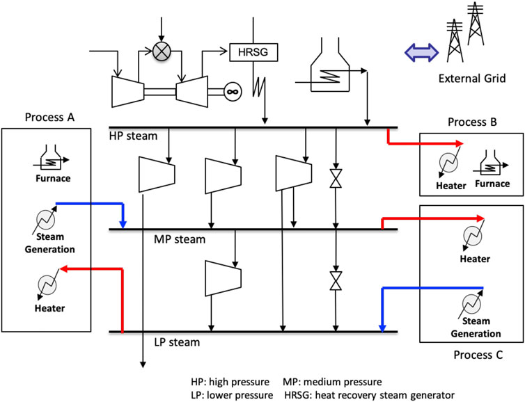
Figure 1. Traditional site utility systems in process industries.
The design of site utility systems is typically carried out with Site Analysis methods, which is illustrated in Figure 2. The industrial site consists of several processes. Each process has different heating and cooling requirements at different temperatures. For example, Process A in Figure 2 needs HP (high pressure) and LP (low pressure) steam, while MP (medium pressure) steam is to be supplied for Process B. Also, steam generation at the process level can be considered for Process B in Figure 2. Site-wide investigation of steam usage is done with the construction of Energy Composite Curves (ECCs) based on process stream data, with which Grand Composite Curves (GCCs) are then obtained. Theoretical minimum requirements of hot and cold utilities for the process at a given minimum approach temperature, ΔTmin, can be estimated. The levels of hot utilities and cold utilities to be supplied and their duty are determined, subject to steam main conditions. This steam-level targeting method is applied to all the subprocesses of the site and these targeting results are collectively combined and used to create Site Composite Curves (SCCs), which represent site-wide characteristics of steam demand and consumption. With SCCs, the site-wide profiles of steam generated by the processes and steam required by the processes are obtained. As shown in Figure 2, two profiles are overlapped, and the gap between two profiles is minimized, which allows to determine maximum steam recovery for the site.
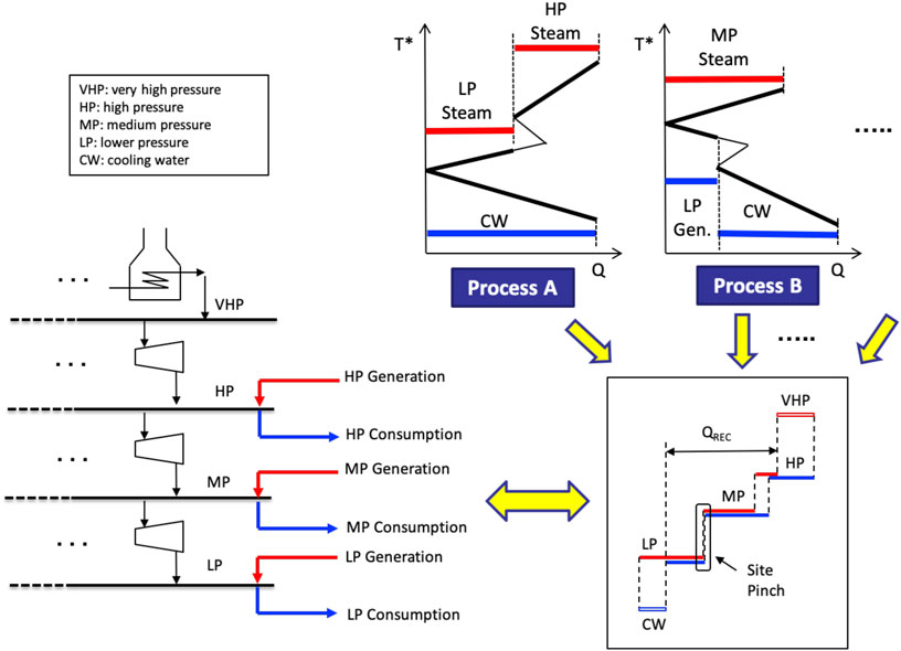
Figure 2. Conventional site analysis.
After the amount of steam recovery for each steam level is determined, the steam production required from the whole site is estimated, which is implemented for the design of site utility systems. Steam balances are set up for steam mains, which provide steam flowrate to be exchanged through steam mains. The number and types of steam generators and steam turbines are selected, which often requires very rigorous optimization with detailed investigation of economic impact. These process-integrated design procedures are well established, and more details can be found from various references. Design methodologies for heat integration and site analysis are well established, which can be found from various references including Kim and Smith (2005), Smith (2016) and Kemp and Lim (2020). More specific topics on the design of site utility systems are addressed by Varbanov et al. (2004) for the process modeling of utility equipment and systems, Iyer and Grossmann (1998) for the mathematical optimization of utility systems, Aguilar et al. (2008) for the consideration of reliability and availability for the design of flexible utility systems, Sun et al. (2015) on the evaluation of steam cost, Hirata et al. (2004) on the multisite integration of utility systems, etc.
Electrified Utility Systems
The industrial utility systems can be transformed through electrified equipment, which utilizes electricity as a main source of energy supply. Various types of electrified equipment are available in industries, and electrified heating can be directly or indirectly applied, covering a wide range of temperatures. For relatively low or medium temperature, either an electric heater may be used for direct heating, while steam generated from an electrode boiler can be used. For high temperature, electric furnaces (or equivalent units based on either induction heating, infrared heating, plasma heating, resistance heating, etc.) can be used. Heat pump is another technology to be used as a means of heat supply through the upgrading of low-grade heat available in the site.
GCCs (Grand Composite Curves) can be used for the selection of electrification technology by evaluating the temperature level of heat and its duty required for the process and matching it with the temperature level of heat supply available. Figure 3 shows an illustrative diagram on how electrified units can be selected for the given GCC. For the illustration purpose, the electric heater is selected for the lower temperature range and the electrode boiler for the medium temperature. However, the selection of types and numbers of electrification units for process heating requires rigorous investigation of economics and practical issues. Also, the introduction of heat pumping is only considered for small or moderate temperature lifting through heat pumping, as a large degree of temperature lifting through vapor compression may not be economically attractive.
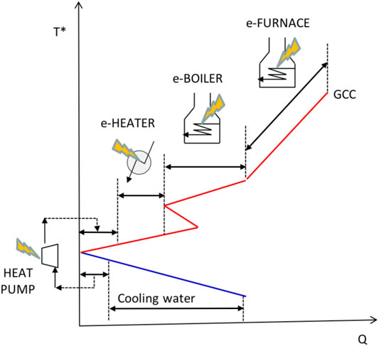
Figure 3. Illustration of heat supply with electrification technologies.
When the steam is produced and distributed as a main energy carrier under traditional fossil fuel-based utility systems, steam generation from waste heat is considered as much as practically possible. Under electrified utility systems, it is more logical to generate the electricity from waste heat sources, which is an additional source for fulfilling electricity demand on the site. One of promising options is the introduction of ORC (Organic Rankine Cycle) which utilizes low grade heat available from processes, as shown in Figure 4. Capital investment related to the ORC should be taken into account when economic gains from additional electricity generated is to be evaluated.
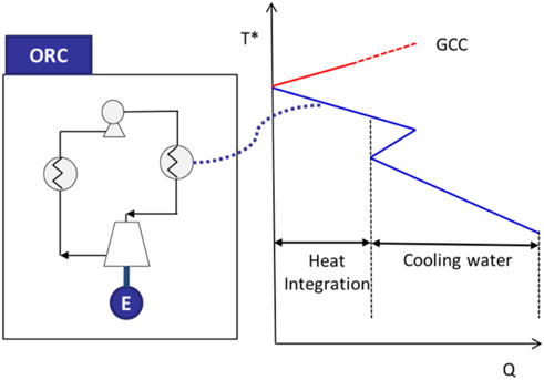
Figure 4. Power recovery under electrified energy management.
When the choice of design options under electrification is made for all the processes of the site, fully-electrified utility systems can be graphically illustrated with Figure 5, in which the electricity main is the main route to supply and distribute an energy carrier–Electricity. The electricity generated from the process can be distributed through the electricity main, which is then interacted with the external grid for further electricity exchange. The choice of electrification technologies is specific to the characteristics of energy demand and heat recovery.

Figure 5. Electrified utility systems.
Although the use of steam through the electrode boiler may be required under the electrified utility systems, the full electrification of utility systems can be materialized in principle. It will be a much simpler configuration for electrified utility systems, as steam-based utility systems require multiple-steam mains which are interconnected with a number of steam generators and steam turbines. Also, electrified utility systems can be inherently less complex because supplementary facilities, for example, boiler feedwater systems, condensate return systems, etc., required for operating steam-based systems can be avoided.
As illustrated in Figure 6, the additional benefit of heat supply from electrified heating is simplicity in the design of heat exchanger networks of downstream processes investigated by Kim et al. (2022). They addressed that the design of heat exchanger networks is likely to be complex with a potentially large number of exchangers when the multiple levels of steam supply are used under steam-based utility systems.
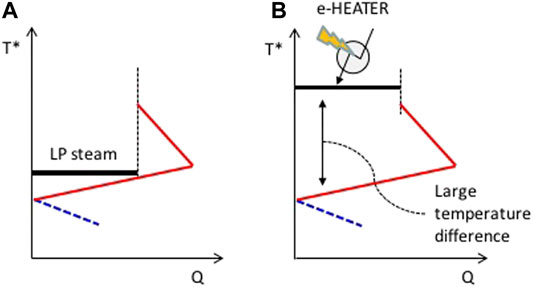
Figure 6. Difference in temperature driving force between steam-based heating (A) and electrified heating (B).
Process Design of Electrified Utility Systems
The design of site utility systems is applied for a medium-sized industrial refinery, which consists of seven processes. The stream data analyzed in this work are taken from the case study of Son et al. (2022), which was originally based on the work of Fraser and Gillespie (1992). Stream data for seven processes are provided in the Supplementary Information. Site utility systems are conceptually designed with electrification scenarios as well as the traditional one based on fossil fuel combustion.
Design of Conventional Utility Systems
The following design procedure is applied for the case study when site utility systems based on conventional steam-based energy supply is to be designed.
1) Process stream data are gathered and validated. The number of steam mains and its operating conditions are selected.
2) With process stream data, Energy Composite Curves (ECCs) for each process are constructed, subject to ΔTmin, which allows to identify theoretical maximum energy recovery feasible for the process.1
3) Grand Composite Curves (GCCs) are constructed for all the processes, based on ECCs obtained.
4) The levels of steam to be supplied and their duty for each process are identified.
5) The duty of the furnace is determined for high-temperature heating in which the use of the steam at the highest temperature level is not feasible.
6) The levels of steam to be generated and their duty are identified with waste heat available from process streams as well as the exhaust gas stream of the furnace.
7) The unrecovered waste heat is discharged to the cold utility available from the site.
8) Utility systems are configured with a single boiler and the number of steam mains chosen. A single turbine is used for the expansion of steam between steam mains.
9) Steam balances are set up for steam mains considered, and the minimum steam flowrate to be generated from the boiler is identified.
10) The steam flowrate to be generated from the boiler is increased, until the overall power demand or requirement for the whole site is satisfied.
11) The configuration of site utility systems may be further evolved to allow multiple steam generators and steam turbines, including gas turbines. Also, the arrangement of the steam turbine network may be further evolved to accommodate multipass turbines. The introduction of additional steam mains or the exclusion of one of steam mains defined in Step (1) may be considered for improving overall economics of site utility systems2.
The following design basis and assumptions are introduced for the calculation of material and energy balances for the site utility systems based on conventional steam-based energy supply:
• A1) A 10°CC of minimum temperature approach (ΔTmin) is assumed for heat recovery3. Heat recovery between process streams is limited within the single process considered. This means that no heat recovery between a process and another process is allowed.
• A2) Three types of steam are available: high pressure (HP) steam at 400°C and 42 bar(a), medium pressure (MP) at 287.3°C and 15 bar(a), and low pressure (LP) at 171°C and 4 bar.
• A3) A 10°C of minimum temperature approach is assumed for site-wide steam generation and recovery. The level of steam use and consumption is targeted against the saturated condition4. Steam generation is maximized with waste heat available from a single process only, not from more than two processes together. Also, a single level of steam at the highest-pressure level allowed is selected for steam generation from the process. When more than one steam level is utilized by the process, the usage of lower pressure steam than higher pressure steam is maximized.
• A4) A 20°C of desuperheating is assumed for the temperature of superheated steam consumed at the process, which accounts for energy loss during steam distribution.
• A5) The configuration of site utility systems is simplified as a single unit is considered for steam and power generation, without evaluating degrees of freedom in process design related to multiple steam generators and steam turbines. The use of desuperheaters is not considered, although its use in industries is common. This is because the let-down equipment is used for improving the operability of steam distribution networks under potential steam imbalance.
• A6) Boiler feed water is assumed to be available at 100°C. Boiler feed water systems are not considered, including LP steam demand for deaeration and condensate loss, as the study is focused on highlighting configurational difference between electrified utility systems and conventional one.
• A7) Site power-to-heat ratio, which characterizes site-wide ratio of power (or electricity) demand to steam demand, is assumed to be about 0.275. This value is selected as a survey of 96 mainstream EU refineries reported the site power-to-heat ratio in the range of 0.09 and 0.38 (CONCAWE, 2012).
• A8) The theoretical flame temperature for furnaces is assumed to be 2,200°C. The waste heat recovery from exhaust gas stream down to 150°C is assumed to be feasible, which is related to practical limitation, known as the acid dew point.
• A9) The unrecovered heat from the process is discharged to the cold utility. The process design of cold utility (i.e., the types, levels, and duty of cooling medium) is not considered in this study.
• A10) The energy efficiency of a steam boiler and a furnace is assumed to be 90%, while that of stream turbines is 75%.
Numerical calculation for steam balances and power generation of steam turbines is made with the aid of a commercial simulator Unisim®. The superheated steam conditions defined in Assumption A2 and the boiler feed water temperature assumed in Assumption A6 are employed for the calculation of steam generation flowrate in t/h from heat available in MW with Unisim®. When the steam flowrate required from processes is to be determined, the degree of desuperheating assumed in Assumption A4 is additionally considered with the superheated steam conditions of A2. Results of Site Analysis from Process one to Process seven is given in Figure 7, which shows Grand Composite Curves for all the seven processes and the results of utility targeting under conventional steam-based utility management. Utility targeting in this study is carried out with the basis for minimizing energy cost as the use of less expensive utility is maximized as much as theoretically possible. Figures 7A–G show the selection of hot and cold utilities to be used and their relevant duty. Furnaces are introduced for Processes three to seven for process heating at high temperature. Steam generation from exhaust gas streams of furnaces for Processes 3, 4, and 6 are considered, while steam generation from exhaust gas streams for Processes five and seven are not considered due to its relatively very small duty available.
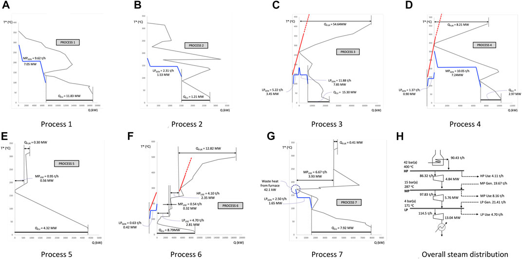
Figure 7. Result of Site Analysis for the case study: Grand Composite Curves (GCCs) with utility targeting for [Process 1 (A)–Process 7 (G)] and a simplified site utility system (H).
Practical limitations or constraints related to the site-wide distribution of steam and/or the steam generation at process level may exist, and the implementation of such issues results in increases for the use of more expensive utilities, compared with the target presented in Figure 7. For example, the use of MP steam for Process 6 may not be favored, due to design complexity involved in steam supply and its integration within the heat exchanger network, and the additional use of HP steam can be seen as a more practical alternative.
The steam generated from the processes are gathered, which are then distributed to processes through steam mains as illustrated in Figure 7H. Overall heating demand for the whole site is estimated as 86.35 MWth, which includes heat duties of furnaces and steam supply. The 90.43 t/h of HP steam generated from the boiler is the flowrate required to generate 23.65 MWe of power from three turbines, which results in the site-wide power-to-heat ratio of 0.274. Additional generation of HP steam and its use for power generation is feasible, which is widely practiced in process industries, although this design issue for increasing site-wide cogeneration is not addressed in this study.
Design of Electrified Utility Systems
The following design procedure is applied for the design of site utility systems under full electrification:
1) Process stream data are gathered and validated, which are then used for constructing Energy Composite Curves (ECCs) and Grand Composite Curves (GCCs) for each process, subject to ΔTmin.
2) The levels of electrified heat supply and their duty for each process are identified. The duty of an electrified furnace is determined for high-temperature heating in which the use of an electric heater or HP steam generated from an electrode boiler is not feasible.
3) If heat supply with heat pumping is feasible, the levels of low-grade heat to be utilized and the heat to be supplied from heat pumping are selected, and their duty is determined.
4) The amount and the temperature level of heat to be recovered from Organic Rankine Cycle (ORC) are determined. When the temperature range for waste heat is considerably large, the use of waste heat at multiple levels for ORCs is considered.
5) The unrecovered waste heat is discharged to the cold utility available from the site.
6) Utility systems are configured with a single electricity main, which is connected with electrified heaters and furnaces of processes as well as ORCs.
It should be noted that the design procedure above is based on the scenario in which the non-electrified energy sources can be fully replaced with electricity for the process. When fuel streams generated from hydrocarbon processing are available, and these by-product fossil fuels should be used within the site, non-electrified units are selected, together with electrified ones in Step (2). Also, the design procedure above is based on the design of site utility systems for a grassroot scenario, not a retrofit of existing plants.
When conceptual design procedures described above are carried out, three assumptions made for the design of conventional utility systems, namely, A1, A6, and A9, are applied. Further design bases with different assumptions given below are introduced to determine material and energy balances of electrified utility systems.
• B1) When process heating above 253.2°C (i.e., saturated condition of HP steam considered in the Design of conventional utility systems section) is involved, the electrified furnace is selected. Otherwise, electric heaters are selected.
• B2) When electric heaters are utilized, the temperature levels for heaters are assumed to be at three steam main conditions considered in the Design of conventional utility systems section.
• B3) The use of electrode boilers is not considered in this case study, as the full electrification of the heat supply is intended without using any kind of steam-related utilities. It should be noted that the electric heaters identified from utility targeting can be, in principle, interchangeable with heat supplies from electrode boilers.
• B4) When the potential for heat pumping exists, the temperature lifting of 50 °C is initially considered. The temperature lifting of heat pumping is also selected such that either the amount of heat used for process heating or that of heat recovered from waste heat is maximized. When the relative difference between these two heat duties is very large, temperature lifting is reduced to be 30°C or increased to be 70°C, depending on the shape of the GCC around the pinch point. COP (coefficient of performance) for heat pumping with 30, 50, and 70°C of temperature lifting is assumed to be 6.1, 4.3, and 2.5, respectively, which is based on the study of Arpagaus et al. (2018).
• B5) When waste heat above 110°C is available, power generation from ORCs is considered. Four different fluids are considered to cover different temperature levels of waste heat to be recovered by the ORC. Butylbenzene is used above 250°C, toluene above 200 C, n-pentane above 150°C and HFC-245fa above 110°C. These fluids are selected such that the critical temperature of fluid is well above the temperature of waste heat to be used. When the multiple levels of ORCs are introduced for a single process, the temperature of waste heat to be rejected to the ORC given should be maximized, and the amount of heat to be rejected to the ORC is determined by considering the shape of GCC, for example, the position of kink points5.
• B6) The amount of electricity generated from the ORC is based on the following equation6:
where, TCRI is the critical temperature of the working fluid in °C, and RORC is the ratio of the amount of electricity generation (WORC) to that of heat utilized (QORC). Eq. 1 is the average performance equations from two regression equations, which are fitted to two sets of performance data of ORCs reported in Lai et al. (2011) and Barse and Mann. (2016).
• B7) The configuration of electrified utility systems is based on a single electricity main, in which electricity is exchanged and distributed throughout the site.
With application of conceptual design procedure and design basis, the electrified energy supply schemes for individual processes are schematically illustrated in Figure 8, in which electrified furnaces, electric heaters, and heat pumps are used as a means of heat suppliers. Figure 8 also shows the potential of electricity generation from ORCs at multiple levels. It should be noted that the number of ORCs to be introduced may be reduced, or one single ORC can be used to accommodate multiple levels of heat rejection from heat sources of processes streams, although this design option is considered to be one of future work.
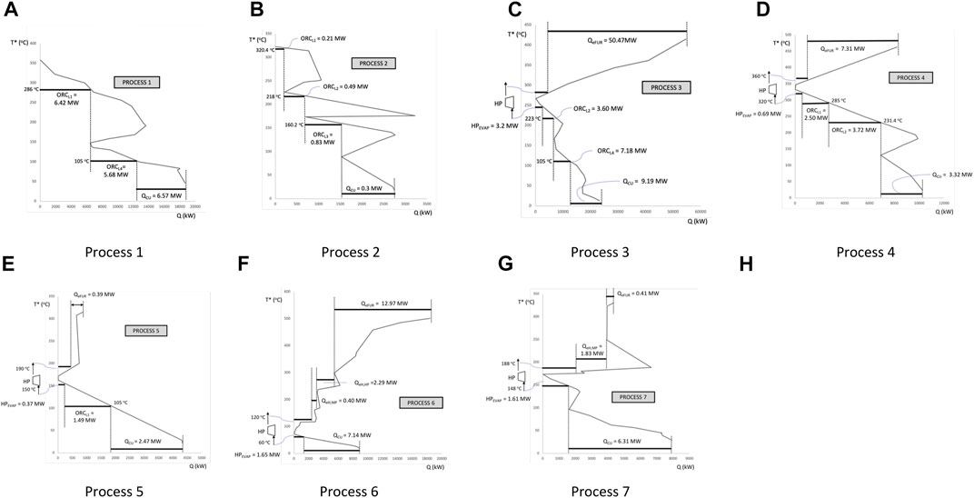
Figure 8. Result of e-Site Analysis under electrification for the case study: GCCs with electrified utility targeting for [Process 1 (A)–Process 7 (G)].
The finalized electrified utility systems are given in Figure 9, which is compared with conventional steam-based utility systems. In addition, Figure 9A shows site-wide generation and distribution of steam via conventional utility systems under specific power-to-heat ratio, while Figure 9B shows site-wide electricity balances for electrified utility systems with no external electricity exchange assumed.
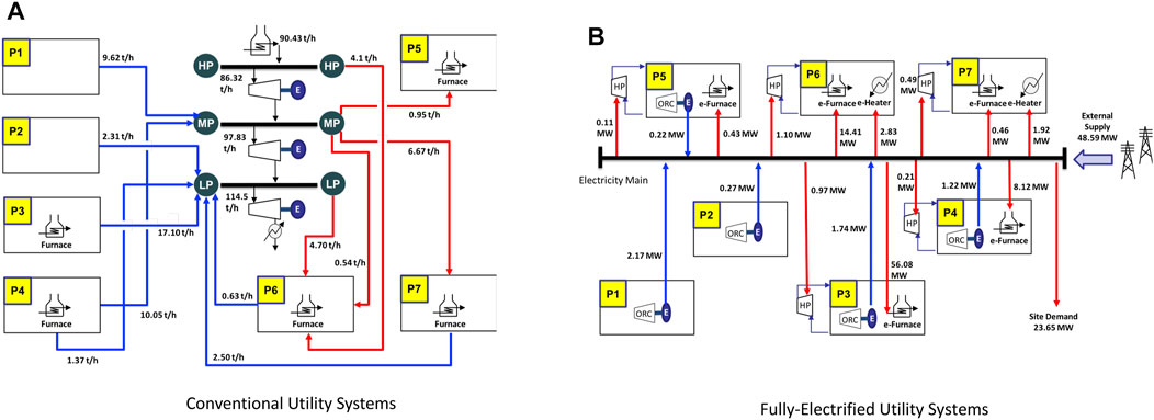
Figure 9. Impact of electrification for site utility systems to Comparison between (A) conventional utility systems and (B) fully-electrified utility systems.
The results of utility targeting under electrification presented in Figure 8 can be further updated with the evolution from initial decisions made for the selection of electrified heat supply options of process heating as well as the determination of heat duty for electrified units. For example, the electric heater may be replaced with electric furnaces or other electrified technology, and heat pumping may not be introduced, due to capital expenditure. ORCs may not be favored when economic advantages from electricity generation at the expense of design complexities are not fully justified. Also, steam can still play a certain role under electrification, when electric heaters for process heating at low and medium temperature range can be replaced with electrode boilers.
The most important benefit of industrial electrification is to support carbon-free energy infrastructure with the use of renewable electricity. Additional benefit for electrified utility systems is to allow much simpler configuration for the site utility systems, which will enhance operability in energy production and its distribution, as illustrated in Figure 8. Differences between conventional utility systems and electrified ones are summarized in Table 1. Under the full use of renewables for electrification of the site, significant reduction in CO2 emissions can be achieved.
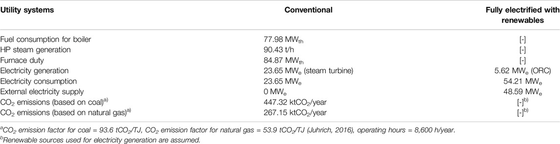
Table 1. Impact of electrification for site utility systems.
Issues to be Discussed
The process design and synthesis procedures are proposed in this work, with which the configuration of site utility systems can be systematically established. This is rather a first-of-a-kind methodology proposed, which requires research areas to be further investigated and additional features to be evaluated in a holistic manner.
• Techno-economic analysis: The environmental benefit for CO2 reduction through electrification should be judged against increase in capital investment for the replacement with electrified units. Although the case study presented gives overall features of site utility systems under electrification, economic impacts related to the full implementation of electrification technologies to the industrial site have not been thoroughly and rigorously evaluated. This is mainly related to lack of reliable costing data for electrified units and system components related to industrial electrification, as the electrification technologies are still in the early stage of development or do not have sufficient track records in industrial practices. Detailed economic evaluation of electrified utility systems is required to understand system-wide economic trade-off between capital cost and operating cost, with which the adequate selection of electrification technologies and its appropriate sizing of equipment can be made with optimal consumption of fuels or energy.
• Design of heat recovery systems: Site-wide supply of process heating and discharge of waste heat from processes are heavily dependent on the degree of heat recovery within the process. For individual processes, the heat recovery is typically envisaged through the design of HEN (heat exchanger networks) in which the number of exchangers and their duty as well as their connectivity between exchangers are determined, typically through rigorous optimization study. Based on the design of HEN, the quality and quantity of hot and cold utilities to be supplied are confirmed. Therefore, the design of site utility systems is inevitably interacted with those of HEN for subprocesses. The heat recovery systems of seven processes in the case study are assumed to achieve theoretical maximum energy recovery, which is used as a design basis for electrified utility systems. As commented in the previous section, it is not anticipated that the full heat recovery is implemented in real practices. This indicates that the capacity of unit operations and energy demand of utility systems presented in the case study are likely to be increased.
• Combined heat and power: The level of cogeneration in conventional utility systems is a very important factor to be determined for energy management, which is often characterized with the site-wide ratio of power to heat, known as R value. This R value represents the effectiveness of fuel for cogeneration, which allows engineers to examine any opportunities for fuel savings through operational improvements or to develop strategies for cost-effective debottlenecking (Kimura and Zhu, 2000). Although the presented case study is based on a typical R value, it should be noted that the choice of R value is very site specific and case dependent, and the selection of R value involves site-wide assessment of utility and energy management. The level of cogeneration had been traditionally determined mainly from the stand-alone assessment of energy demand for the site. However, interactions with external energy prosumers, for example, the export of low-grade heat from the site to the local district heating network, or the import of renewable electricity from the external sources, are expected to be increased, which will be an important factor for future electrified energy systems in process industries.
• Internal fuel generation: In petrochemical industries, a wide range of hydrocarbon streams are produced as byproducts from the result of various cracking and conversion processes. These streams are limited to be upgraded or be utilized further, other than to be used as fuels for energy generation. The fuel consumption and fuel mix in petrochemical processes strongly depends on the refinery configuration, and the type, yield and quality of a range of refining products. Most petrochemical plants are operated with the consumption of external energy input, as the amount of fuels internally generated within the site is not sufficient (Brueske et al., 2012). This indicates that 100% of electrification may not be achievable for the certain type of process industries when byproduct fuels generated from internal processing should be consumed within the site. The industrial electrification for such cases is illustrated in Figure 10, in which the electrified processing coexists with conventional processing heating based on internal byproduct fuels, for example, refinery fuel gas or petroleum coke.
• Process steam use: The complete exclusion of steam may not be practically feasible for a certain processing, in which steam may be used as process streams, not utility streams, for example, steam used as a part of feed stream for a reactor, or steam used as a stripping agent. The generation of steam through waste heat recovery as illustrated in Figure 10 or from the electrode boiler can be considered under electrified utility systems.
• Practical constraints: The current study does not fully accommodate any practical issues, for example, limitation of plant layout, operational preference for simple network configuration, etc. Such issues can be very critical for retrofit scenarios, in which gains from the introduction of new units should be economically viable enough to justify the replacement or modification of existing units. As a kind-of-first attempt for proposing a new design framework, the methodology presented in this paper does not consider issues of RAM (reliability, availability, and maintainability) related to the management of site utility systems, for example, the introduction of additional units as standby units for potential failure, the consideration of spare units or additional capacity for improving availability, etc. As there are many rotating machines to be used in process industries, another benefit of electrification can be improvement in process availability through more use of electric drivers.
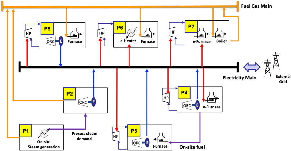
Figure 10. Illustration of electrified utility systems with the internal use of byproduct fuels.
Conclusion
Site-wide energy management of process industries under industrial electrification is addressed to gain our conceptual understanding for the design and operation of electrified utility systems, compared with conventional fossil fuel-based utility systems. Impact of electrified units on the overall energy production, and its distribution through utility systems is discussed. e-Site Analysis, a new design method for the process synthesis of utility systems under electrification, is proposed, with which the generation, utilization, and distribution of electricity, as a main energy carrier, in process industries can be practiced for process industries. The applicability of new design frameworks for industrial utility systems is illustrated with a case study, with which conceptual insights for the transformation to future electrified energy systems in process industries are gained.
Data Availability Statement
The original contributions presented in the study are included in the article/Supplementary Material, further inquiries can be directed to the corresponding author.
Author Contributions
J-KK is the sole author for the work presented.
Funding
This work was supported by the National Research Foundation of Korea (NRF) (No. 2019R1A2C2002263) funded by the Korea government (MSIT).
Conflict of Interest
The author declares that the research was conducted in the absence of any commercial or financial relationships that could be construed as a potential conflict of interest.
Publisher’s Note
All claims expressed in this article are solely those of the authors and do not necessarily represent those of their affiliated organizations, or those of the publisher, the editors and the reviewers. Any product that may be evaluated in this article, or claim that may be made by its manufacturer, is not guaranteed or endorsed by the publisher.
Supplementary Material
The Supplementary Material for this article can be found online at: https://www.frontiersin.org/articles/10.3389/fther.2022.861882/full#supplementary-material
Footnotes
1It should be noted that the actual amount of energy recovery for the process is less than the maximum one in practice, due to practical limitations or constraints existing for heat recovery systems.
2This step is not considered in this study, which requires rigorous process modeling and optimization of site utility systems.
3The selection of an optimal ΔTmin value is highly case specific, which requires rigorous economic trade-off between energy and capital cost for exchangers. This issue is beyond the scope of the work presented.
4The superheated conditions and BFW (boiler feed water) heating are considered during targeting, not to have any temperature violation against GCCs.
5A wide range of working fluids are available for temperatures up to 300°C (Arpagaus et al., 2018), and the selection of a working fluid for ORCs, together with determination of optimal operating conditions, should be made with rigorous thermodynamic analysis and optimization study.
6As the energy efficiency of ORCs strongly depends on the configuration of working cycles and its operating conditions, rigorous process modeling and its evaluation are required to obtain accurate estimation of electricity generated.
References
Aguilar, O., Kim, J.-K., Perry, S., and Smith, R. (2008). Availability and Reliability Considerations in the Design and Optimisation of Flexible Utility Systems. Chem. Eng. Sci. 63, 3569–3584. doi:10.1016/j.ces.2008.04.010
Aguilar, O., Perry, S., Kim, J., and Smith, R. (2007). Design and Optimisation of Flexible Utility Systems Subject to Variable Conditions – Part 2: Methodology and Applications. Chem. Eng. Res. Des. 85 (A8), 1149–1168. doi:10.1205/cherd06063
Arpagaus, C., Bless, F., Uhlmann, M., Schiffmann, J., and Bertsch, S. S. (2018). High Temperature Heat Pumps: Market Overview, State of the Art, Research Status, Refrigerants, and Application Potentials. Energy 152, 985–1010. doi:10.1016/j.energy.2018.03.166
Barse, K. A., and Mann, M. D. (2016). Maximizing ORC Performance with Optimal Match of Working Fluid with System Design. Appl. Therm. Eng. 100 (5), 11–19. doi:10.1016/j.applthermaleng.2016.01.167
Berenschot (2017). Electrification in the Dutch Process Industry. Available at: https://cedelft.eu/wp-content/uploads/sites/2/2021/04/3K02_Finalreport_1489735856.pdf (Accessed on January 2, 2022).
Beyond Zero Emissions Inc (2018). Zero Carbon Industry Plan: Electrifying Industry. Melbourne, Australia: Beyond Zero Emissions Inc.
Brueske, S., Sabouni, R., Zach, C., and Andres, H. (2012). U.S. Manufacturing Energy Use and Greenhouse Gas Emissions Analysis. Washington, DC: US DOE. ORNL/TM-2012/504).
Chen, C., Lu, Y., and Banares-Alcantara, R. (2019). Direct and Indirect Electrification of Chemical Industry Using Methanol Production as a Case Study. Applied Energy 243, 71–90.
CONCAWE (2012). “EU Refinery Energy Systems and Efficiency,”. Report No. 3/12 (Brussels, Belgium: CONCAWE).
Duckett, A. (2021). Greener Chemicals: Steam Cracking Could Go Electric by 2023. The Chem. Engineer. March 2021 Issue 957.
Fraser, D. M., and Gillespie, N. E. (1992). The Application of Pinch Technology to Retrofit Energy Integration of an Entire Oil Refinery. Trans. Inst. Chem. Eng. 70 (A), 395–406.
Hirata, K., Sakamoto, H., O’Young, L., Cheung, K. Y., and Hui, C. W. (2004). Multi-scale Utility Integration – an Industrial Case Study. Comp. Chem. Eng. 28 (1-2), 139–148. doi:10.1016/s0098-1354(03)00176-5
Huang, Y., Pang, H., Ding, P., Zhang, B., Lee, K. Y., and Wang, B. (2021). Multi-Objective Optimization of Steam Power System under Demand Uncertainty. IEEE Access 9, 113130–113142. doi:10.1109/access.2021.3104110
IEA (2020). The Role of CCUS in Low-Carbon Power Systems. Paris, France: International Energy Agency.
Iyer, R. R., and Grossmann, I. E. (1998). Synthesis and Operational Planning of Utility Systems for Multiperiod Operation. Comput. Chem. Eng. 22, 979–993. doi:10.1016/s0098-1354(97)00270-6
Jadun, P., McMillan, C., Steinberg, D., Muratori, M., Vimmerstedt, L., and Mai, T. (2017). Electrification Futures Study: End-Use Electric Technology Cost and Performance Projections through 2050. Golden, CO: National Renewable Energy Laboratory. NREL/TP-6A20-70485. Available at: https://www.nrel.gov/docs/fy18osti/70485.pdf.
Juhrich, K. (2016). CO2 Emission Factors for Fossil Fuels - Climate Change 27/2016. Dessau-Roßlau, Sachsen-Anhalt: German Environmental Agency.
Kemp, I., and Lim, J. S. (2020). Pinch Analysis for Energy and Carbon Footprint Reduction: User Guide to Process Integration for the Efficient Use of Energy. 3rd Ed. Amsterdam, Netherlands: Elsevier.
Kim, J.-K., Son, H., and Yun, S. (2022). Heat Integration of Power-To-Heat Technologies: Case Studies on Heat Recovery Systems Subject to Electrified Heating. J. Clean. Prod. 331, 130002. doi:10.1016/j.jclepro.2021.130002
Kim, J., and Smith, R. (2005). Pinch Design and Analysis. New York, New York, United States: Marcel Dekker: Encyclopaedia of Chemical Processing, 2165–2180.
Kimura, H., and Zhu, X. X. (2000). R-curve Concept and its Application for Industrial Energy Management. Ind. Eng. Chem. Res. 39 (7), 2315–2335. doi:10.1021/ie9905916
Klemes, J. J., Varbanov, P. S., Alwi, S. R. W., Manan, Z. A., Fan, Y. V., and Chin, H. H. (2018). Sustainable Process Integration and Intensification Saving Energy, Water and Resources. Berlin, Germany: De Gruyter.
Lai, N. A., Wendland, M., and Fischer, J. (2011). Working Fluids for High-Temperature Organic Rankine Cycles. Energy 36 (1), 199–211. doi:10.1016/j.energy.2010.10.051
Lechtenböhmer, S., Nilsson, L. J., Åhman, M., and Schneider, C. (2016). Decarbonising the Energy Intensive Basic Materials Industry through Electrification - Implications for Future EU Electricity Demand. Energy 115, 1623–1631. doi:10.1016/j.energy.2016.07.110
Leenders, L., Ganz, K., Bahl, B., Hennen, M., Baumgärtner, N., and Bardow, A. (2021). Scheduling Coordination of Multiple Production and Utility Systems in a Multi-Leader Multi-Follower Stackelberg Game. Comput. Chem. Eng. 150, 107321. doi:10.1016/j.compchemeng.2021.107321
Liew, P. Y., Theo, W. L., Wan Alwi, S. R., Lim, J. S., Abdul Manan, Z., Klemeš, J. J., et al. (2017). Total Site Heat Integration Planning and Design for Industrial, Urban and Renewable Systems. Renew. Sustain. Energ. Rev. 68, 964–985. doi:10.1016/j.rser.2016.05.086
Linnhoff, B., Townsend, D. W., Boland, D., Hewitt, G. F., Thomas, B. E. A., Guy, A. R., et al. (1982). A User Guide on Process Integration for the Efficient Use of Energy. UK: IChemE.
Madeddu, S., Ueckerdt, F., Pehl, M., Peterseim, J., Lord, M., Kumar, K. A., et al. (2020). The CO2 Reduction Potential for the European Industry via Direct Electrification of Heat Supply (Power-to-heat). Environ. Res. Lett. 15, 124004. doi:10.1088/1748-9326/abbd02
McKinsey and Company (2020). Plugging-in: What Electrification Can Do for Industry? Available at: https://www.mckinsey.com/industries/electric-power-and-natural-gas/our-insights/plugging-in-what-electrification-can-do-for-industry (accessed on January 2, 2022).
Morgan, E. R. (2013). “Techno-economic Feasibility Study of Ammonia Plants Powered by Offshore Wind,” . Phd Thesis (US: University of Massachusetts Amhest).
Perry, S., Klemeš, J., and Bulatov, I. (2008). Integrating Waste and Renewable Energy to Reduce the Carbon Footprint of Locally Integrated Energy Sectors. Energy 33 (10), 1489–1497. doi:10.1016/j.energy.2008.03.008
Rena, X. Y., Jiab, X., Varbanov, P. S., Klemeš, J., and Liu, Z. Y. (2017). Calculation of Cogeneration Potential of Total Site Utility Systems with Commercial Simulator. Chem. Eng. Transaction 61, 1231–1236.
Schuwer, D., and Schneider, C. (2018). “Electrification of Industrial Process Heat: Long-Term Applications, Potentials and Impacts,” in Proceedings of the ECEEE Industrial Summer study, Kalkscheune, Berlin. Germany, 11–13 June 2018, 411–422.
Son, H., Kim, M., and Kim, J.-K. (2022). Sustainable Process Integration of Electrification Technologies with Industrial Energy Systems. Energy 239, 122060. doi:10.1016/j.energy.2021.122060
Sun, L., Doyle, S., and Smith, R. (2015). Heat Recovery and Power Targeting in Utility Systems. Energy 84, 196–206. doi:10.1016/j.energy.2015.02.087
Sun, L., Doyle, S., and Smith, R. (2016). Understanding Steam Costs for Energy Conservation Projects. Appl. Energ. 161, 647–655. doi:10.1016/j.apenergy.2015.09.046
Svensson, E., Wiertzema, H., and Harvey, S. (2021). Potential for Negative Emissions by Carbon Capture and Storage from a Novel Electric Plasma Calcination Process for Pulp and Paper Mills. Front. Clim. 3, 705032. doi:10.3389/fclim.2021.705032
Varbanov, P. S., Doyle, S., and Smith, R. (2004). Modelling and Optimization of Utility Systems. Chem. Eng. Res. Des. 82 (5), 561–578. doi:10.1205/026387604323142603
Wiertzema, H., Ahman, M., and Harvey, S. (2018). “Bottom-up Methodology for Assessing Electrification Options for Deep Decarbonisation of Industrial Processes,” in Proceedings of the ECEEE Industrial Summer study, Kalkscheune, Berlin. Germany, 11–13 June 2018, 389–397. European Council for an Energy Efficient Economy (ECEEE).
Keywords: electrification, e-site analysis, utility systems, cogeneration, process design
Citation: Kim J-K (2022) e-Site Analysis: Process Design of Site Utility Systems With Electrification for Process Industries. Front. Therm. Eng. 2:861882. doi: 10.3389/fther.2022.861882
Received: 25 January 2022; Accepted: 22 February 2022;
Published: 12 April 2022.
Edited by:
Guilian Liu, Xi’an Jiaotong University, ChinaReviewed by:
Di Zhang, Inner Mongolia University of Technology, ChinaMinbo Yang, Xi’an Jiaotong University, China
Copyright © 2022 Kim. This is an open-access article distributed under the terms of the Creative Commons Attribution License (CC BY). The use, distribution or reproduction in other forums is permitted, provided the original author(s) and the copyright owner(s) are credited and that the original publication in this journal is cited, in accordance with accepted academic practice. No use, distribution or reproduction is permitted which does not comply with these terms.
*Correspondence: Jin-Kuk Kim, amlua3Vra2ltQGhhbnlhbmcuYWMua3I=