 Kyungsoo Kim
 Ruoyu Wei
 Yoon Hyuk Kim
95% of researchers rate our articles as excellent or good
Learn more about the work of our research integrity team to safeguard the quality of each article we publish.
Find out more
BRIEF RESEARCH REPORT article
Front. Surg. , 30 November 2022
Sec. Orthopedic Surgery
Volume 9 - 2022 | https://doi.org/10.3389/fsurg.2022.1011432
This article is part of the Research Topic Clinical Application of Medical Imaging for Functional Evaluation in Orthopaedics View all 21 articles
It is strongly challenging to obtain functional movement of the pelvis based on the three-dimensional (3D) dynamic anterior pelvic plane (APP) orientation information. This study provided the 3D APP orientation measurement technique by registration with an inertial measurement unit (IMU), and its reliability was tested. The local coordinate systems of the APP and the IMU sensor were registered using two images of the pelvic part from the frontal and left sagittal views in a neutral standing posture. Then, the measurement errors in the APP orientation were analyzed by comparing the values obtained from manually measured four points in the IMU sensor and the known exact values in 10 different postures. Moreover, the errors between values obtained from manually measured three anatomical points and the known exact values were also compared. The average errors were quite small (less than 0.6°) when measuring from three anatomical points and were acceptable (1.6°–3.4°) when measuring from four points in the IMU sensor. These results indicate that the measurement of APP direction using four points in the IMU sensor could be considered reliable in terms of intra-participant and inter-participant. The present technique to register the IMU sensor position and the APP direction by taking X-ray images from the frontal and sagittal directions can be fundamental information to measure the APP direction during dynamic motion when the IMU position is obtained from the IMU sensor data instead of the four-point location information.
Total hip arthroplasty (THA) is a highly successful surgical intervention to restore the hip joint function and relieve pain in patients with symptomatic end-stage osteoarthritis (OA) of the hip (1). THA is also the primary treatment method for femoral neck fracture and osteonecrosis of femoral head (1). The anterior pelvic plane (APP) formed by the bilateral anterior superior iliac spines and the upper margin of the pubic symphysis was regarded as an anatomical reference for the navigation system during THA (2, 3). The pelvic tilt (PT) was defined as the angle of the APP relative to a vertical axis, and many reports denoted a certain relationship between PT and acetabular anteversion and lumbar back deformity (4, 5).
Several useful radiological-imaging techniques have been reported to obtain the APP orientation (6–12). Radiological imaging was limited to a certain posture and it merely provided the frontal and sagittal views (6–10). The computed tomography and ultrasound device can provide a three-dimensional (3D) reconstruction of the pelvic bony model to analyze the normal direction of the APP plane, but these methods easily led to APP orientation errors because of soft-tissue thickness (6–10). The EOS imaging system can provide a high-quality image and is reliable for assessing the APP orientation with lower radiation (11, 12). However, it can only provide a static posture and is also difficult to maintain in proper position while taking measurements. Therefore, a 3D pelvis-motion measurement system will be useful in clinical fields since it can resolve certain weaknesses in previous technologies.
Recently, inertial measurement units (IMUs) have been widely utilized in clinical and rehabilitation settings. The IMU is a small electric device that measures velocity and acceleration, angular velocity and acceleration, and orientation of the body using accelerometers, gyroscopes, and/or magnetometers (13–17). Functional movement of the lumbar spine was measured with the IMUs for assessment of movement-related disorders (13). The IMU-based wearable device has been used for measuring spinal shape and posture (14–16) and performing sport motion analysis (17). Moreover, the PT was analyzed using one IMU sensor (18, 19). However, it is strongly challenging to obtain functional movement of the 3D dynamic APP orientation information. This study provided the 3D APP orientation measurement technique by registration with an IMU, and its reliability was tested.
The 3D orientation of APP can be represented by two linearly independent vectors: a normal vector to APP and a vector included in the APP (20). The following procedure aims to find two vectors to represent the APP from the position information of the IMU sensor.
The local coordinate system for the IMU sensor can be defined by four points (end points of the horizontal and vertical bars attached to the IMU sensor), while the local coordinate system for the APP can be defined by three points (two anterior superior iliac spine points and a marginal point on the pubic tubercles). Two images of the pelvic part from the frontal and left sagittal views in a neutral standing posture were used to register the local coordinate systems of the APP and the IMU sensor (Figure 1A). The two images were obtained by virtually projecting a 3D pelvic bony model with the IMU sensor from the frontal and left sagittal views, where the 3D pelvic model was developed in our previous study (21). Those images included the four points (, , , and ) from the IMU sensor and the three points (, , and ) from the APP. Here, and were the top and bottom end points of the vertical bar, and and were the left and right end points of the horizontal bar. and were the left and right anterior superior iliac spine points, and was the marginal point on the pubic tubercles. The x-, y-, and z-axes in the global coordinate system were from left to right, from back to front, and from bottom to top, respectively.
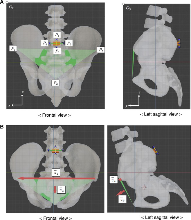
Figure 1. Frontal and left sagittal images of pelvic model, including the IMU sensor and the APP. (A) Neutral standing posture. (B) Flexion 30° posture.
In the frontal and left sagittal figures, the top left corner points were set as the origins and . Next, the horizontal and vertical distances in pixel from to were defined by and . Similarly, the horizontal and vertical distances in pixel from to were and .
Let us define and for the local coordinate system of the IMU sensor and and for the local coordinate system of the APP. However, the scales of the frontal and left sagittal figures may not match. Since the real distance of and in the z-direction in each figure should be the same, and represented the same length. By assuming the and as a unit length in each figure, the vector can be obtained with , , , and as
where the x-component and y-component are normalized by the and , respectively, and the z-component is the mean of z-components normalized by the and . Then, , , , and are represented by
Three unit vectors, , , and , construct an orthonormal basis for the local coordinate system of the IMU sensor. Let the matrix be . Moreover, another three unit vectors, , , and , represent the APP orientation, where is the normal vector to the APP, and is a vector included in the APP from left to right anatomical points. Two vectors, and , are used as reference unit vectors to estimate the APP orientation in other postures.
To geometrically understand and , the latitude and longitude concepts are introduced. The latitude of a vector is defined as an angle between the vector and the xy-plane, where the +z direction is +90° and the –z direction is –90°. The longitude of a vector is defined as an angle between the vector and zx-plane, where the x-direction is 0° and the y direction is 90° (Figure 2).
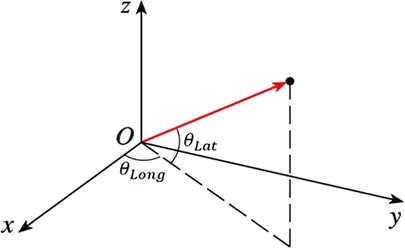
Figure 2. Definition of the latitude and longitude of a vector.
In an arbitrary posture, the normal vector to the APP and the vector from the left to right anatomical points can be estimated when frontal and left sagittal figures are given, only including the four end points in bars attached to the IMU sensor. Let the four points be , , , and . As in the neutral standing posture, three unit vectors, , , and , can be obtained and construct an orthonormal basis for the local coordinate system of the IMU sensor in an arbitrary posture. Let the matrix U be . Under the assumption that the IMU sensor and the APP were attached to the pelvis, the normal vector to the APP and the vector from left to right anatomical point in the arbitrary posture can be estimated as and (Figure 1B). Let and be the latitude and longitude of , and , and be the latitude and longitude of .
Two vectors, and , also can be obtained using , , and , which are three anatomical points in the arbitrary posture. Two calculation methods should result in the same vectors based on the fundamental linear algebra. However, there may be measurement errors when obtaining and since the pixel values of points are manually measured.
To investigate the reliability in measuring the 3D APP orientation only using positional information from one IMU sensor, 10 volunteers (26.1 ± 3.5 years old, visual acuity 0.86 ± 0.45) participated in the test experiment with the written informed consent. An Android tablet (Samsung Galaxy Tab S3 9.7, Korea) was used to collect point data and touch pencil was used to mark the four points in the IMU sensors and the three anatomical points (Figure 3). Each participant clicked seven points on frontal and left sagittal images from eleven different image sets and repeated the experiment five times with randomly reordered image sets.
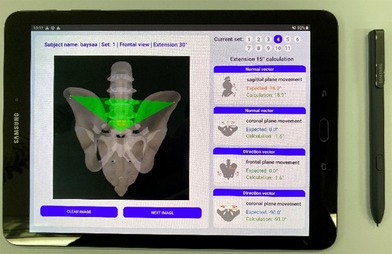
Figure 3. Android tablet/pencil used in the experiment.
The 11 image sets were obtained using the 3D pelvic bony model: (1) neutral standing posture, (2) flexion 15°, (3) extension 15°, (4) extension 30°, (5) right rotation 15°, (6) right rotation 30°, (7) left bending 15°, (8) left bending 30°, (9) extension 15° and right rotation 15°, (10) right rotation 15° and left bending 15°, and (11) extension 15° and right bending 15°. First, the 3D pelvic bony model (21) with the IMU sensor was set to the given posture among the 11 postures using commercial CAD software. The images were then taken by projecting the 3D model from frontal and left sagittal views. Thus, the exact values of , , , and in a given posture were known. Then, the measurement errors in , , , and were analyzed by comparing the values obtained from manually measured four points in the IMU sensor and the known exact values. Moreover, the errors between values obtained from manually measured three anatomical points and the known exact values were also compared. The average errors of all participants' results from five trials were analyzed. The interclass correlation coefficients (ICCs) among 10 participants for , , , and were investigated in each measurement cases, using four points in the IMU sensor and using three anatomical points.
Table 1 shows the average and standard deviation (SD) of errors in , , , and of 11 image sets for each participant when the error was calculated from three anatomical points. Additionally, the average ± SD of 10 averages were provided as 0.6° ± 0.2°, 0.5° ± 0.2°, 0.3° ± 0.1°, and 0.5° ± 0.2°, while the average ± SD of 10 SDs were 0.3° ± 0.1°, 0.5° ± 0.2°, 0.2° ± 0.1°, and 0.5° ± 0.2° in , , , and . All averages and SDs were less than 1°. The ICCs among 10 participants for , , , and were 0.9954, 0.9058, 0.9967, and 0.9979, respectively.
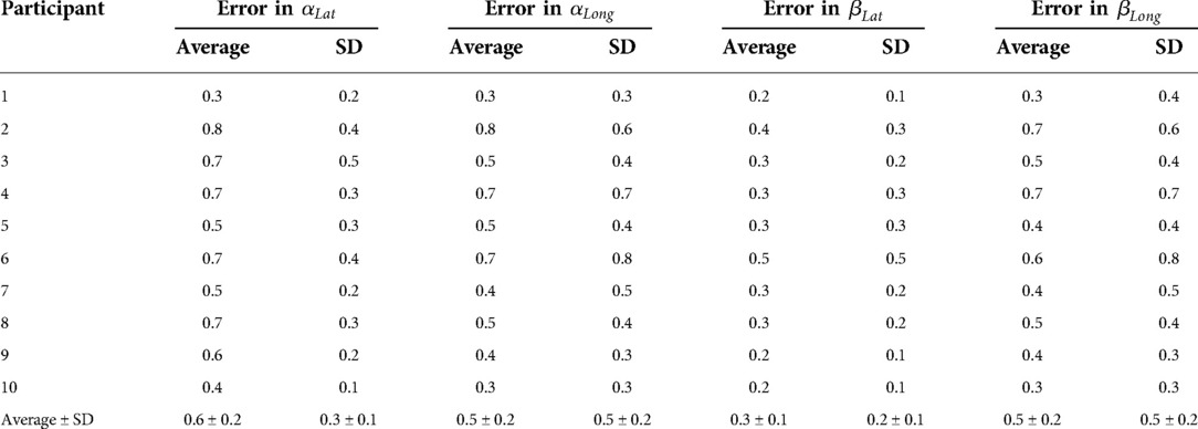
Table 1. Errors from manually measured three anatomical points (unit: °).
Table 2 shows the average and SD of errors in , , , and of 11 image sets for each participant when using four points in the IMU sensor. The average ± SD of 10 averages were also presented as 3.4° ± 0.3°, 2.0° ± 1.0°, 1.6° ± 0.4°, and 2.1° ± 0.8°, while the average ± SD of 10 SDs were 0.9° ± 0.4°, 1.1° ± 0.4°, 0.6° ± 0.2°, and 1.1° ± 0.4° in , , , and . The maximum average and SD of errors were 4.0° in for participant 6 and 2.0° in for participant 2. The ICCs among 10 participants for , , , and were 0.9933, 0.9668, 0.9933, and 0.9671, respectively.

Table 2. Errors from manually measured four points in the IMU sensor (unit: °).
In measuring from three anatomical points, the average errors in , , , and were quite small (less than 0.6°). The SDs for the image set and the participant, which were related to the variability according to the image set and the participant, were also very small (less than 0.3° and 0.5°). Moreover, the ICCs for four angles were greater than 0.9. These results indicate that the measurement of the APP direction using three anatomical points could be considered accurate; thus, it can be used as the true value of APP direction due to the difficulty in the direct measurement of the APP direction in a common clinical setting.
In measuring from four points in the IMU sensor, the average errors in , , , and were acceptable (1.6°–3.4°) in comparison with errors or variations (2°–10°) provided in previous studies (2, 19, 22). Lewinnek et al. proposed 10° of margin in inclination and an anteversion of cup position in THA as a safe zone (2). Wang et al. demonstrated seventy-five percent of the errors across all measurements were within 5° of the radiograph measurements (19). Kalteis et al. showed that the precision of acetabular cup inclination and anteversion were 3° and 10° with plain X-rays, while those were approximately 2° with CT-scan (22). In addition, the SDs for the image set and the participant, which were related to the variability according to the image set and the participant, were also very small (less than 1.4° and 1.1°). Similar to the measurement from three anatomical points, the ICCs for four angles were greater than 0.9. These results also indicate that the measurement of APP direction using four points in the IMU sensor could be considered reliable in terms of intra-participant and inter-participant.
The technique presented in this study, the registration of the IMU sensor position and the APP direction determined from three anatomical points and four IMU points by taking X-ray images from the frontal and sagittal directions, can be applied to measure the APP direction during dynamic motion when the IMU position is obtained from the IMU sensor data instead of the four-point location information. In future study, the registration of the IMU position from four points and the IMU position data from the three inside sensors (accelerometers, gyroscopes, and magnetometer) can be completely obtained by calculating the orthonormal matrix from the local coordinate system in the IMU sensor position to that in the IMU sensor data. Then, the APP direction can be predicted from the IMU sensor data.
There were limitations in this study. Various anatomical and biomechanical factors, which could generate additional error such as the soft tissue tension, contracture, and skin movement as well as the body mass index and pelvic deformation, should be considered in order to enhance the clinical relevance. In addition, more participants can improve statistical confidence since the sample size of study (10 participants) was relatively small.
This study provided the 3D APP orientation measurement technique by registration with an IMU, and its reliability was tested. The measurement errors in the APP orientation were analyzed by comparing the values obtained from manually measured four points in the IMU sensor and the known exact values in different postures. Moreover, the errors between values obtained from manually measured three anatomical points and the known exact values were also compared. The average errors were quite small when measuring from three anatomical points and were acceptable when measuring from four points in the IMU sensor. The ICCs among participants were greater than 0.9 in both measurements. These results indicate that the measurement of APP direction using four points in the IMU sensor could be considered reliable in terms of intra-participant and inter-participant. The present technique to register the IMU sensor position and the APP direction by taking X-ray images from the frontal and sagittal directions can be fundamental information to measure the APP direction during dynamic motion when the IMU position is obtained from the IMU sensor data instead of the four-point location information.
The raw data supporting the conclusions of this article will be made available by the authors, without undue reservation.
KK and YK contributed to conception and design and RW contributed to acquisition of data. KK, RW, and YK performed analysis and interpretation of data. All authors contributed to the article and approved the submitted version.
This work was supported by the National Research Foundation of Korea (NRF) grants funded by the Korea government (MSIP) (NRF-2017R1A2B1010492 and NRF-2021R1A2C1011825).
The authors declare that the research was conducted in the absence of any commercial or financial relationships that could be construed as a potential conflict of interest.
All claims expressed in this article are solely those of the authors and do not necessarily represent those of their affiliated organizations, or those of the publisher, the editors and the reviewers. Any product that may be evaluated in this article, or claim that may be made by its manufacturer, is not guaranteed or endorsed by the publisher.
1. Ferguson RJ, Palmer AJ, Taylor A, Porter ML, Malchau H, Glyn-Jones S. Hip replacement. Lancet. (2018) 392(10158):1662–71. doi: 10.1016/S0140-6736(18)31777-X
2. Lewinnek GE, Lewis JL, Tarr R, Compere CL, Zimmerman JR. Dislocations after total hip-replacement arthroplasties. J Bone Joint Surg Am. (1978) 60(2):217–20. doi: 10.2106/00004623-197860020-00014
3. Blondel B, Parratte S, Tropiano P, Pauly V, Aubaniac JM, Argenson JN. Pelvic tilt measurement before and after total hip arthroplasty. Orthop Traumatol Surg Res. (2009) 95(8):568–72. doi: 10.1016/j.otsr.2009.08.004
4. Roussouly P, Pinheiro-Franco JL. Biomechanical analysis of the spino-pelvic organization and adaptation in pathology. Eur Spine J. (2011) 20(Supp 5):609–18. doi: 10.1007/s00586-011-1928-x
5. Yang G, Li Y, Zhang H. The influence of pelvic tilt on the anteversion angle of the acetabular prosthesis. Orthop Surg. (2019) 11(5):762–9. doi: 10.1111/os.12543
6. DiGioia AM, Hafez MA, Jaramaz B, Levison TJ, Moody JE. Functional pelvic orientation measured from lateral standing and sitting radiographs. Clin Orthop Relat Res. (2006) 453:272–6. doi: 10.1097/01.blo.0000238862.92356.45
7. Nishihara S, Sugano N, Nishii T, Ohzono K, Yoshikawa H. Measurements of pelvic flexion angle using three-dimensional computed tomography. Clin Orthop Relat Res. (2003) 411:140–51. doi: 10.1097/01.blo.0000069891.31220.fd
8. Lee YS, Yoon TR. Error in acetabular socket alignment due to the thick anterior pelvic soft tissues. J Arthroplasty. (2008) 23(5):699–706. doi: 10.1016/j.arth.2007.06.012
9. Babisch JW, Layher F, Amiot LP. The rationale for tilt adjusted acetabular cup navigation. J Bone Joint Surg Am. (2008) 90(2):357–65. doi: 10.2106/JBJS.F.00628
10. Fritz B, Agten CA, Boldt FK, Zingg PO, Pfirrmann CWA, Sutter R. Acetabular coverage differs between standing and supine positions: model-based assessment of low-dose biplanar radiographs and comparison with CT. Eur Radiol. (2019) 29(10):5691–9. doi: 10.1007/s00330-019-06136-5
11. Lazennec JY, Rousseau MA, Rangel A, Gorin M, Belicourt C, Brusson A, et al. Pelvis and total hip arthroplasty acetabular component orientations in sitting and standing positions: measurements reproductibility with EOS imaging system versus conventional radiographies. Orthop Traumatol Surg Res. (2011) 97(4):373–80. doi: 10.1016/j.otsr.2011.02.006
12. Thelen T, Thelen P, Demezon H, Aunoble S, Le Huec J-C. Normative 3D acetabular orientation measurements by the low-dose EOS imaging system in 102 asymptomatic subjects in standing position: analyses by side, gender, pelvic incidence and reproducibility. Orthop Traumatol Surg Res. (2017) 103(2):209–15. doi: 10.1016/j.otsr.2016.11.010
13. Beangea KHE, Chan ADC, Beaudette SM, Graham RB. Concurrent validity of a wearable IMU for objective assessments of functional movement quality and control of the lumbar spine. J Biomech. (2019) 97(3):109356. doi: 10.1016/j.jbiomech.2019.109356
14. Wong WY, Wong MS. Trunk posture monitoring with inertial sensors. Eur Spine J. (2008) 17(5):743–53. doi: 10.1007/s00586-008-0586-0
15. Voinea G-D, Butnariu S, Mogan G. Measurement and geometric modelling of human spine posture for medical rehabilitation purposes using a wearable monitoring system based on inertial sensors. Sensors. (2016) 17(1):3. doi: 10.3390/s17010003
16. Stollenwerk K, Müller J, Hinkenjann A, Krüger B. Analyzing spinal shape changes during posture training using a wearable device. Sensors. (2019) 19(16):3625. doi: 10.3390/s19163625
17. Khuyagbaatar B, Purevsuren T, Kim YH. Kinematic determinants of performance parameters during golf swing. Proc Inst Mech Eng H. (2019) 233(5):554–61. doi: 10.1177/0954411919838643
18. Wada T, Nagahara R, Gleadhill S, Ishizuka T, Ohnuma H, Ohgi Y. Measurement of pelvic orientation angles during sprinting using a single inertial sensor. Proc AMIA Annu Fall Symp. (2020) 49:10. doi: 10.3390/proceedings2020049010
19. Wang X, Qureshi A, Vepa A, Rahman U, Palit A, Williams MA, et al. A sensor-based screening tool for identifying high pelvic mobility in patients due to undergo total hip arthroplasty. Sensors. (2020) 20(21):6182. doi: 10.3390/s20216182
21. Khurelbaatar T, Kim K, Kim YH. A cervico-thoraco-lumbar multibody dynamic model for the estimation of joint loads and muscle forces. J Biomech Eng. (2015) 137(11):111001. doi: 10.1115/1.4031351
Keywords: anterior pelvic plane, orientation, inertial measurement units, registration, hip
Citation: Kim K, Wei R and Kim YH (2022) Reliability in measurement of three-dimensional anterior pelvic plane orientation by registration with an inertial measurement unit. Front. Surg. 9:1011432. doi: 10.3389/fsurg.2022.1011432
Received: 4 August 2022; Accepted: 3 November 2022;
Published: 30 November 2022.
Edited by:
Yan Yu, Tongji University School of Medicine, ChinaReviewed by:
Suk Kyoon Song, Catholic University of Daegu, South Korea© 2022 Kim, Wei and Kim. This is an open-access article distributed under the terms of the Creative Commons Attribution License (CC BY). The use, distribution or reproduction in other forums is permitted, provided the original author(s) and the copyright owner(s) are credited and that the original publication in this journal is cited, in accordance with accepted academic practice. No use, distribution or reproduction is permitted which does not comply with these terms.
*Correspondence: Yoon Hyuk Kim, eW9vbmhraW1Aa2h1LmFjLmty
†These authors have contributed equally to this work and share first authorship
Specialty Section: This article was submitted to Orthopedic Surgery, a section of the journal Frontiers in Surgery
Disclaimer: All claims expressed in this article are solely those of the authors and do not necessarily represent those of their affiliated organizations, or those of the publisher, the editors and the reviewers. Any product that may be evaluated in this article or claim that may be made by its manufacturer is not guaranteed or endorsed by the publisher.
Research integrity at Frontiers
Learn more about the work of our research integrity team to safeguard the quality of each article we publish.