 R. Trautner1*
 S. J. Barber2R. Fisackerly1D. Heather1B. Houdou1C. Howe3S. Iacobellis1M. Leese2A. Mariani4G. Meogrossi5
 N. Murray6C. Panza5
 P. Reiss7A. Rusconi5F. Abernethy2
 N. Cann1
 H. Chinnery2
 C. Gscheidle7P. Landsberg2R. Lindner1
 A. D. Morse2J. Mortimer2
 L. Nicolae1P. Picchi4S. Sheridan2A. Verchovsky2
- 1European Space Agency, ESA/ESTEC, Noordwijk, Netherlands
- 2School of Physical Sciences, The Open University, Milton Keynes, United Kingdom
- 3RAL Space / STFC, Fermi Ave, Harwell, Didcot, United Kingdom
- 4Kayser Italia S.r.L., Livorno, Italy
- 5Leonardo S.p.A., Airborne & Space Systems Division, Nerviano, Italy
- 6Dynamic Imaging Analytics Ltd, Foxhunter Drive, Milton Keynes, United Kingdom
- 7Technical University of Munich, Ottobrunn, Germany
PROSPECT is a comprehensive payload package developed by the European Space Agency which will support the extraction and analysis of lunar surface and subsurface samples as well as the acquisition of data from additional environmental sensors. The key elements of PROSPECT are the ProSEED drill and the ProSPA analytical laboratory. ProSEED will support the acquisition of cryogenic samples from depths up to 1 m and deliver them to the ProSPA instrument. ProSPA will receive and seal samples in miniaturized ovens, heat them, physically and chemically process the released volatiles, and analyze the obtained constituents via mass spectrometry using two types of spectrometers. Contextual information will be provided by cameras which will generate multi-spectral images of the drill working area and of acquired samples, and via temperature sensors and a permittivity sensor that are integrated in the drill rod. The package is designed for minimizing volatile loss from the sample between acquisition and analysis. Initially developed for a flight on the Russian Luna-27 mission, the payload package design was adapted for a more generic lander accommodation and will be flown on a lunar polar lander mission developed within the NASA Commercial Lunar Payload Services (CLPS) program. PROSPECT targets science and exploration in lunar areas that might harbor deposits of volatiles, and also supports the demonstration of In-Situ Resource Utilization (ISRU) techniques in the lunar environment. PROSPECT operations are designed to be automated to a significant degree but rely on operator monitoring during critical phases. Here, we report the PROSPECT flight design that will be built, tested, and qualified according to European space technology engineering standards before delivery to the lander provider for spacecraft integration. The package is currently in the hardware manufacturing and integration phase with a target delivery to the NASA-selected CLPS lander provider in 2025.
1 Introduction
The renewed international interest in lunar science and lunar resources is generating numerous opportunities for performing scientific experiments and testing in-situ resource utilization (ISRU) technologies on the lunar surface. Water and other volatiles are of particular interest, with the potential for significant abundance of water ice near the lunar south pole suggested by the M3 instrument on Chandrayaan-1 (Pieters, 2009) and confirmed by NASA’s LCROSS mission, which impacted an empty rocket stage into a crater on the lunar surface and identified ice in the ejected plume (Colaprete, 2010). These results, in combination with thermal modeling showing the potential stability of water ice at depth across large portions of the lunar south pole in particular (e.g., Paige and Pieters, 2010; King et al., 2020), have suggested that these regions may be host to a far more significant amount of water than was previously thought. The exact distribution, form, quantity, and origins of any water or hydroxyl are still untested, requiring direct sampling and surface analyses, and these are some of the questions that PROSPECT aims to address.
The PROSPECT package provides a comprehensive set of sample acquisition and handling functionalities as well as multiple types of instrumentation to address science and exploration goals. PROSPECT was initially developed to a preliminary design stage for a flight on the Russian Luna-27 lunar lander (Trautner et al., 2018), and has since then been re-designed, refined and matured to become a more generic payload package suitable for accommodation on different lunar lander platforms. With a strong focus on acquisition of samples containing lunar volatiles that are expected to be found predominantly in lunar polar areas, PROSPECT is designed for flight opportunities to high latitude landing sites. The first flight opportunity is on a mission of NASA’s CLPS program, designated as CP-22, for a landing in 2026. PROSPECT will acquire samples for analysis from the surface down to a maximum sampling depth of 1 m and compile a comprehensive inventory of lunar polar volatiles found in the exosphere, surface regolith, and the subsurface at the landing site. This investigation will be supported by several secondary instruments and sensors that will provide additional data on landing site context and sample characteristics.
2 PROSPECT overview
The PROSPECT package consists of two key subassemblies: the ProSEED drill, which supports the acquisition of samples from the lunar surface and subsurface up to a depth of ∼1 m, and the ProSPA instrument, which allows the analysis of acquired samples by means of volatile extraction, gas processing and mass spectrometry techniques. The electrical interface to the lander is provided by the ProSEED Control Electronics Unit (CEU), which connects to the spacecraft’s payload control unit via two power links and a serial data link. ProSEED provides a Positioner Rotation Joint (PRJ) that allows the selection of a drilling site within the constraints of its working area and includes an imaging system and a permittivity sensor for supporting science and to achieve engineering-related objectives like the assessment of operational risks. The drill provides two different sampling mechanisms for acquiring samples of different sizes; the smaller sample type is suitable for the ProSPA instrument. ProSPA consists of two separate subassemblies, the Solids Inlet System (SIS) and the Analytical Package (AP). Samples acquired by the drill are delivered to the SIS, where they are imaged and sealed in miniature ovens before analysis. The SIS functionality is managed by the electronics in the Local Electronics System (LES) in the AP. The ProSPA instrument draws power from the ProSEED CEU and connects to it via a SpaceWire (SpW) link. ProSPA includes two mass spectrometers and a flexible set of functionalities for processing the acquired samples and the released volatiles. High-level control of the PROSPECT package functions, such as data exchange with the host platform and management of command sequences, is provided by the ProSEED CEU, while ProSPA functions are controlled at AP level. The unified interface to the lander simplifies the integration with the platform and allows the synchronization of ProSPA and ProSEED operations without lander interaction, which reduces the complexity of PROSPECT operations and system testing.
PROSPECT is expected to be accommodated on the side of the lander that is facing poleward after landing. This minimizes solar irradiation during drilling and allows keeping acquired samples at minimum temperatures during sample acquisition and sample transfer. A typical configuration for accommodation on a lander is depicted in Figure 1. The relative positioning of the PROSPECT units is governed by some specific constraints that are explained in subsequent chapters.
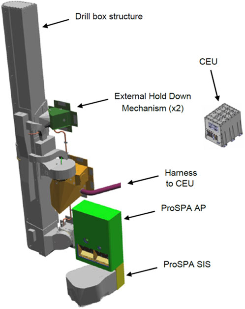
Figure 1. The elements of the PROSPECT package, schematically depicted in a typical accommodation configuration. Left: ProSEED drill box with External Hold Down Mechanisms (EHDMs) and positioner base tower/rotation joint; center: ProSPA Analytical Package with SIS installed below; right: PROSPECT CEU. The harness connection from CEU to ProSEED drill box and AP is not shown in detail.
2.1 Industrial/academic consortium
The PROSPECT package is developed under a contract from the European Space Agency (ESA). The industrial consortium is led by Leonardo S.p.A. (Italy) who are also developing the ProSEED drill in collaboration with lower-level subcontractors Beyond Gravity (Switzerland, PRJ mechanism), Maxon (Switzerland, actuators), Sener (Spain, DTJ mechanisms), Kayser Italia S.r.L. (Italy, imaging system and EGSE), 3DPLUS/Lambda-X (France/Belgium, camera head), and Astronika (Poland, mechanisms). The ProSPA instrument is provided by key subcontractor The Open University (United Kingdom) in collaboration with lower-level subcontractors Airbus Defence and Space (United Kingdom, thermal design), RAL Space (United Kingdom, electronics and software), Technical University of Munich (Germany, SIS/ISRU technology and permittivity sensor), Max-Planck Institute for Solar System Research (Germany, SIS mechanisms), DIAL (United Kingdom, sample imager) and Leonardo S.p.A. (Utaly, mechanisms) (Italy, mechanisms).
In parallel to the industrial/academic project consortium, PROSPECT science investigations are actively supported and accompanied by a dedicated PROSPECT Science Team, which comprises researchers from several European industrial and academic institutions alongside some US participants.
2.2 Key science objectives and volatile preservation
The key science objective for PROSPECT is the detection and characterization of lunar polar volatiles in surface and subsurface samples. In this context, the preservation of volatiles in acquired samples up to the analysis stage is among the main challenges for PROSPECT.
When a volatile-bearing sample is acquired, the mechanical acquisition by the ProSEED sampling tool implies a first potential loss of volatiles due to thermal interaction with the temperature-controlled hardware. During extraction of the sample from the subsurface and up to delivery to the ProSPA instrument an additional volatile loss occurs. Another potential volatile loss is expected during the period from receiving the sample in the SIS up to sealing the sample in the oven. Finally, the leakage of oven seals and valves up to and during the gas analysis in the AP also imply a potential loss of volatiles. It is possible and necessary (but non-trivial) to model the losses for these operational steps in order to reduce the overall measurement error on volatile quantity in the sample; related work to investigate this in more detail is supported by separate ESA contracts.
The effect of volatile loss is illustrated in Figure 2. The upper solid line (black) leading from pristine sample (left side) to the point of sample analysis (right side) indicates the loss of volatiles from the sample during the acquisition, transfer, sealing and analysis stages. The blue line leading back from measurement result to derived sample volatile content makes use of volatile loss models. The dashed blue lines depict the error bars for the derived volatile content resulting from Mass Spectrometer (MS) measurement error and volatile loss modeling errors.
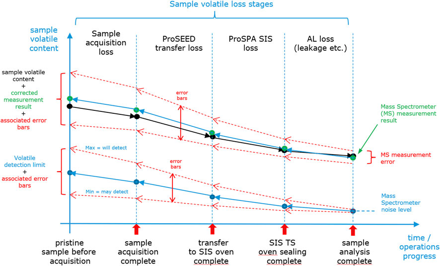
Figure 2. Qualitative depiction of the impact of sample volatile loss on measurement accuracy and volatile detection limits.
The quality of volatile loss modeling is also important for the instrument’s volatile detection limits, as the detection limit of the spectrometers (determined by noise and background levels) is amplified by the volatile loss that is incurred up to the point of measurement. This is depicted in the lower curve in Figure 2. The sensitivity limit for volatile detection can be derived from the MS noise level and the reconstruction of the incurred volatile loss. The resulting error for the detection limit is derived from the combined modeling errors for the individual volatile loss stages.
Key requirements for reducing volatile loss include keeping the sample temperature as low as possible and minimizing the time spent from sample acquisition to sample sealing. These constraints are influenced by multiple factors including achievable mechanism speed, drill-regolith interaction (friction, conductive heat transfer), shadowing of drilling site, drill rod and SIS, thermal interface and accommodation aspects, and related operational approaches. The volatile loss varies for different molecular species, as their isotopic fractionation is also temperature dependent; as a result the volatile loss needs to be limited to ensure accurate measurements (Mortimer et al., 2018). These factors need to be taken into account for volatile loss modeling.
For PROSPECT, volatile loss can be minimized by several means. First, allowing the drill tool to cool down after drilling and before sample acquisition limits the drill tip temperature and related desorption of volatile content in the sample. Second, it is beneficial to design (on lander level) for a sufficiently low SIS interface temperature, ideally around −50 °C and not exceeding 0 °C during surface operations. Third, choosing an appropriate SIS cooldown period before a sample is delivered will allow the ovens to reach an appropriate temperature for sample reception. Furthermore, the time between sample transfer to the oven and sample sealing is affected by the choice of the oven on the carousel; some ovens imply a shorter or longer transfer time depending on their relative positions on the rotary mechanism. Finally, the acquisition of accurate temperature information for the hardware elements involved in the sample handling and transfer will support volatile loss modeling. As a result, considering these factors will enable an appropriate level of volatile preservation and an improved science return from interpreting the obtained measurement data.
2.3 Technical interfaces
Table 1 provides a summary of key interface and functional aspects.
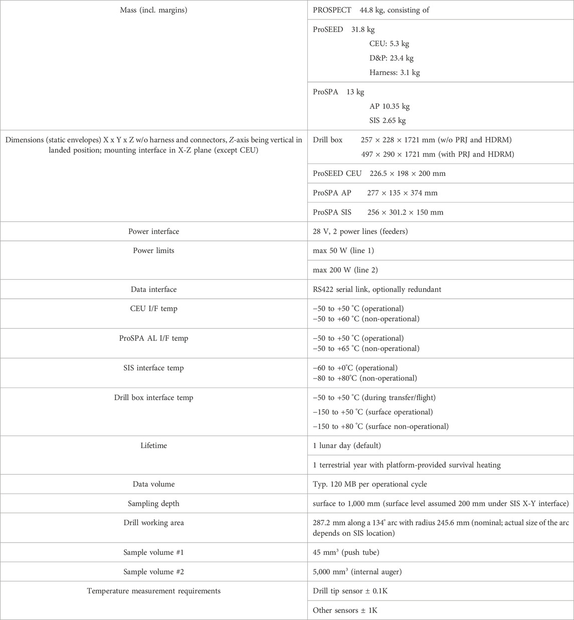
Table 1. Key interface and sample acquisition characteristics of the PROSPECT Package.
While the basic technical interfaces of the individual PROSPECT sub-units (ProSEED box, CEU, ProSPA AL and SIS) are well defined, the details of their accommodation on a lander depend on the selected platform. This will however not affect the basic performance of the PROSPECT package as long as the baseline accommodation requirements are met.
2.4 ProSEED
The ProSEED main subassemblies consists of Drill and Positioner (whose main task is the sample collection, transportation, and delivery of collected samples to ProSPA) and Control Electronics Unit (CEU) which houses the electronics controlling the whole PROSPECT package. In terms of instrumentation the key subassemblies are the ProSEED Imaging System IS (used to acquire images and videos during lunar surface operations) and the ProSEED permittivity sensor which provides both science and engineering data. Additional hardware includes the ProSEED Harness (connecting the CEU with the other units) and the ProSEED Multi-Layer Insulation (MLI) that serves as thermal insulator for the ProSEED package. The following paragraphs describe the main ProSEED subassemblies and the integrated instrumentation.
2.4.1 ProSEED CEU
The ProSEED CEU is the ‘brain’ of the overall PROSPECT package and provides the electrical (power, data) interfaces to the platform and to the ProSPA instrument. It controls the ProSEED drill mechanisms, acquires data from a range of sensors, and handles telecommands (TC) and telemetry (TM) for the ProSPA instrument. The CEU acts as the data buffer not only for ProSEED data sources (ProSEED housekeeping data, drill telemetry, ProSEED Imaging System science and housekeeping data, permittivity sensor data) but also for all ProSPA data. It supports generic lossless data compression (CCSDS 121) and lossy image compression (CCSDS 122) on PROSPECT science data and on parts of the housekeeping data, prevents failure propagation to the platform, and provides important FDIR functions. The CEU provides high levels of power for the drill and for ProSPA. Power and data interfaces are non-redundant in the baseline implementation, but a redundant option is supported by the hardware design. The PROSPECT CEU is closely based on a similar unit developed in ESA’s ExoMars project (Vago et al., 2017) and is designed as a highly reliable system.
2.4.2 ProSEED drill and Positioner
The ProSEED drill consists of a drill box of considerable size (over 1.7 m in vertical height), and several mechanisms supporting the drill positioning and drilling functions. The drill box is a carbon fiber based construction which encloses the key drilling mechanisms, and which also interfaces externally to the rest of the Drill and Positioner unit (see Figure 3).
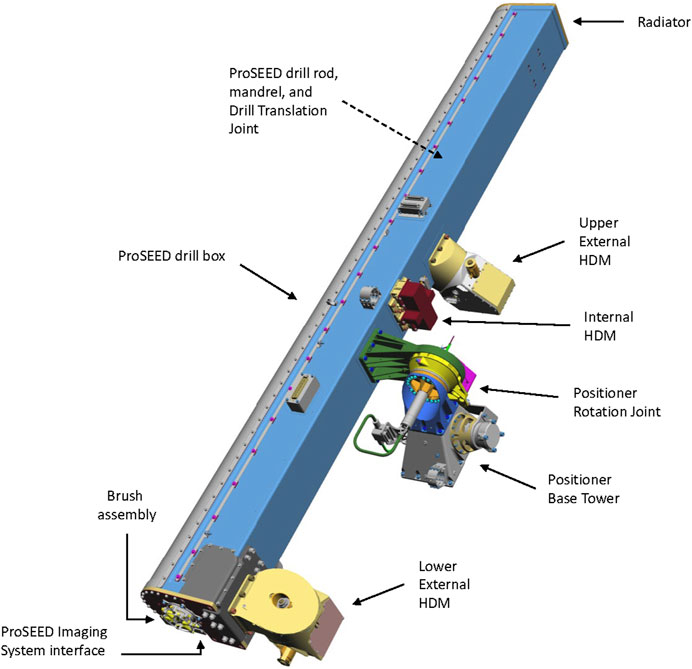
Figure 3. ProSEED drill box and main subassemblies. MLI is not shown in this depiction.
The bottom end of the drill box includes the mounting position for the ProSEED imaging system (see 2.4.3) and a set of brushes in contact with the drill rod for reducing dust ingress into the box.
The drill rod includes the sampling tool (shown in detail in Figure 4), a device developed by the PROSPECT prime contractor Leonardo, which is capable of collecting 2 dry or icy samples of different sizes and physical-mechanical properties in a single sampling operation. This has been successfully tested during PROSPECT Phase B+ via a dedicated test campaign with representative lunar regolith simulant in cryogenic conditions and with variable water content up to saturation.
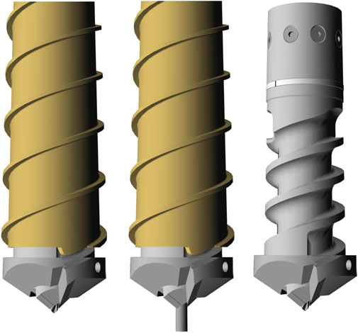
Figure 4. ProSEED sampling tool design. The sampling device used for acquisition of ProSPA samples is a push tube (left: retracted, middle: deployed). An additional sampling mechanism is provided for higher volume samples (right side, shown without drill rod tube) which allows acquisition of larger volumes of loose sample material. Both sample types are acquired while drilling; the push tube remains extended after sample acquisition until sample delivery, while for the larger sample the auger is retracted after acquisition to contain the sample within the drill rod until delivery.
The drill rod also includes the PROSPECT permittivity sensor which provides information on subsurface material dielectric constant and also supports the direct detection of medium to high quantities of water ice in the regolith.
There are critical requirements defining the relative positioning of the ProSEED drill and the ProSPA SIS, as the capability of the SIS to compensate for drill rod misalignment during sample transfer is limited and the relative positioning needs to meet the requirements after application of launch, landing, and deployment loads over an extended temperature range.
The sampling tool and permittivity sensor are accommodated at the end of the drill rod, which itself interfaces near the top of the drill box with the Mandrel. The Mandrel provides the rotational torque which is transmitted to the drill cutting face by the drill rod. Working alongside the Mandrel is the Drill Translation Joint (DTJ), consisting of a geared mechanism in the base of the box which rotates a lead screw coupled with an interface nut on the Mandrel, and which provides the vertical thrust for advancing the drill cutting face down into the lunar surface. The DTJ is also used for overall translation of the drill rod, e.g., in retrieving the sample from the subsurface, and in positioning the sampling tool for sample transfer to the ProSPA SIS.
Supporting the drill rod within the drill box is an Internal Hold Down Mechanism (IHDM) which, together with other preloads and launch constraints, ensure the drill rod and its mechanisms can sustain the launch vibration.
A Positioner Rotation Joint (PRJ) is attached externally to the drill box and connects it, via a Positioner Base Tower, to the lander platform. The PRJ provides a rotational ‘horizontal’ degree of freedom, for choosing and accessing different drilling sites along an arc of approximately 90°, and for positioning the drill above the ProSPA SIS for sample delivery.
Before surface commissioning, the Drill box is also attached to the lander platform with two dedicated External Hold Down Mechanisms (EHDMs) which ensure the overall Drill and Positioner can sustain the launch environment. These EHDMs are then released during the surface commissioning phase, from which time the PRJ can rotate the drill box along the working area arc.
2.4.3 ProSEED imaging system
The ProSEED Imaging System (IS) will provide high resolution and multispectral images before, during and after the drilling activities. It can acquire 10 fps video in support of capturing the drill-regolith interaction and for monitoring purposes. In terms of science, the imaging system allows to investigate the mineralogy of surface and subsurface materials by means of multispectral imaging in a spectral range from 451 to 970 nm. It also supports PROSPECT operations verification and Public Relations objectives by provision of images and video. It allows witnessing the delivery of samples and an assessment of the positioning accuracy of drill tip vs. SIS inlet.
For multispectral imaging, an Artificial Illumination Unit (AIU) provides illumination in six spectral bands based on high power Light Emitting Diodes (LEDs), see Table 2. The LEDs are arranged in a Bayer-type pattern shown in Figure 5, and their beam angles are selected such that the decrease of the quantum efficiency of the IS detector towards higher wavelengths is partially compensated in order to achieve a sufficient signal-to-noise ratio at the FOV center for all wavelengths.
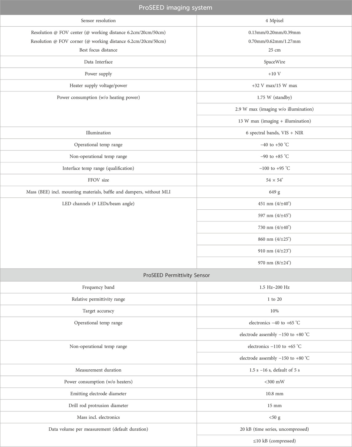
Table 2. Key characteristics of the drill-integrated instrumentation.
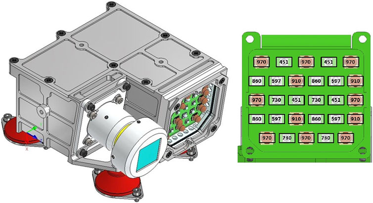
Figure 5. ProSEED Imaging System (IS) design (left) and LED spectral channel arrangement (right). The IS is mounted to the drill box via a set of dampers (depicted in red) for reducing mechanical loads during launch, EHDR release, and drilling.
Due to power limitations, the optical power output of the AIU is not sufficient to perform high S/N multispectral imaging in the presence of direct sunlight. It is therefore important to ensure that relevant parts of the scenes of interest (such as parts of the cuttings cone) are in shadow when the imaging system is employed for this science investigation. This can be enabled by sunshields provided by the lander, and by selecting the drilling location according to the local time and the shadows cast by the lander, drill rod, and cuttings cone.
A color calibration target is also provided; its accommodation is foreseen at the base of the SIS where it can be imaged periodically when witnessing sample deliveries.
2.4.4 ProSEED permittivity sensor
The ProSEED permittivity sensor (Trautner et al., 2021a) is accommodated in the rod of the ProSEED drill as illustrated in Figure 6. It allows to sense the dielectric properties of the surrounding materials via the emission of an extremely low Frequency (ELF) alternating current (AC) signal through a small electrode. Apart from the capability to detect water ice, it measures regolith density and porosity of the subsurface and the drill cuttings that are transported upwards along the auger. This supports the estimation of sample mass from the sample volume measurements performed by ProSPA’s SamCam (see 2.5.1). Measurements can be taken either at distinct drilling depths and drill rod angular positions, or in the context of a horizontal scan where multiple measurements are taken at a specific depth, with the drill rod being rotated by a small angle between subsequent measurements.
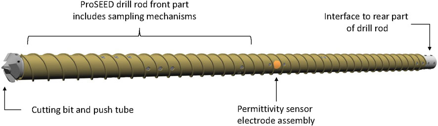
Figure 6. ProSEED drill rod (front part) and permittivity sensor accommodation.
Performing multiple horizontal scans at equidistant depths allows the compilation of an electrical subsurface image, which provides information about permittivity trends with depth, the distribution of rocks embedded in the subsurface in proximity to the drill rod, and about the presence of subsurface ice within the sensor’s detection limits. The sensor also allows to assess the size of the gap between drill rod and borehole wall, and provide inputs to the assessment of operational risks. A prototype of the permittivity sensor has been tested successfully in cryogenic conditions, demonstrating the capability to detect water ice at temperatures around −130 °C (Trautner et al., 2021a). Further optimizations of electrode design and data processing techniques implemented for the flight model design are expected to lead to a detection limit for ice concentrations of < 1wt% at regolith temperatures around 125 K. Some key characteristics of the sensor are summarized in Table 2.
2.5 ProSPA
ProSPA comprises two physical units–the Solids Inlet System (SIS) that contains a number of single-use sample ovens on a rotary carousel together with a sample imager (SamCam) and an oven sealing mechanism, and a miniaturized Analytical Package (AP) incorporating elements for volatile processing, two mass spectrometers, and associated ancillary and control systems. Both units are connected by a harness and by the gas transfer pipe which is heated during operation. The SIS requires a mounting position that provides alignment of the ProSEED drill tip with the SIS sample inlet for enabling the transfer of acquired samples. The separate arrangement of SIS and AP allows provision of a separate thermal interface for the SIS to operate at low temperature and therefore minimize the loss of volatiles during sample handling, whereas the AP unit and its embedded electronics operate at more conventional (warmer) hardware temperatures. The AP can be mounted at some distance to the SIS, but with constraints for the maximum gas transfer pipe length, resulting harness mass, and SIS radiator field of view clearance. The functions of both AP and SIS are managed by software running on the processor of the Local Electronics System (LES) that is embedded in the AP. ProSPA is controlled by telecommands routed to the LES by the ProSEED CEU. All data generated by ProSPA is initially buffered in the LES and forwarded to the ProSEED CEU for further processing, data compression and storage. The overall architecture of ProSPA is depicted in Figure 7. The following chapters describe the instrument’s SIS and AP subunits.
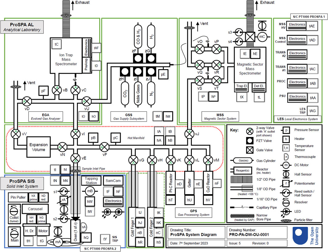
Figure 7. ProSPA functional diagram showing internal subunits: SIS (bottom left, blue box) and AP elements (green boxes): Gas Processing System (center), EGA/ITMS (top left), MSS (top right), and LES as well as legenda (black box, right side).
2.5.1 Solids inlet system
The Solids Inlet System (SIS) provides the necessary functions for receiving a sample from the ProSEED drill, measuring the sample volume, sealing the sample in one of its ovens, and performing controlled release of volatiles from the sample via heating of the sealed oven. Additional functions include the optical characterization of the samples in the spatial and spectral domains, cooling of the ovens for minimizing sample volatile loss, and temperature measurements for controlling the volatile release and for aiding volatile loss modeling. Figure 8 illustrates the SIS design.

Figure 8. ProSPA Solids Inlet System design (MLI cover and connections to AP not shown).
Samples obtained from the lunar surface or subsurface by ProSEED are delivered to the SIS via a sequence of steps. First, the drill rod is positioned above the SIS delivery position. The drill tip is lowered slowly, allowing the alignment collet (a funnel-like device that has a rotational degree of freedom (DOF) at an angle to the ProSEED rotational joint DOF) to adjust to the drill tip position. ProSEED is continually adjusting the drill rod position using information from a lateral force sensor while moving downwards. The SIS collet assembly is connected to a position sensor; position information is fed back to ProSPA to align the oven position with the collet position. Once drill, collet and oven are aligned the push tube which contains the sample is retracted while the drill rod is moving downwards, and the sample is discharged into the target oven. The carousel assembly in the SIS allows accommodation of up to 25 ovens; an option to replace one oven by a SamCam calibration target may be chosen for missions where utilization of all ovens is considered unlikely due to mission constraints. After sample delivery, the carousel is rotated to place the sample-containing oven under the SamCam imager (Murray et al., 2020) to confirm the presence of a sample, determine its reflectance spectrum in a range from 450 to 970 nm, and enable an estimation of the sample volume via plenoptic imaging (see example image in Figure 9). Then the target oven is rotated to the Tapping Station (TS) position where an actuator is used to seal the oven to a pipe that runs to the AL. The quality of the seal is an important factor for volatile preservation; the chosen material (polytetrafluoroethylene) allows reliable sealing also in the presence of lunar dust and up to temperatures of 322 °C reached at the seal interface. To achieve the required thermal gradient between the heated zone inside the oven (up to 950 °C) and the seal at the top of the oven, various detail design features are incorporated to minimize heat transfer through conduction and radiation.
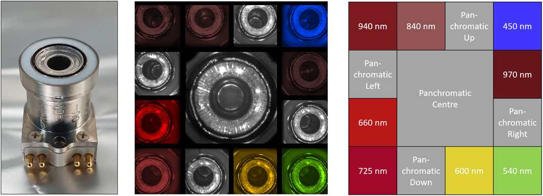
Figure 9. ProSPA SIS oven (left), SamCam image of oven (center), and SamCam optical filter characteristics (right).
As the SIS is radiatively cooled, a cool-down phase is required after each sample analysis to allow the thermal energy released in the SIS during sample heating to dissipate and radiate away, so the SIS and specifically the ovens are cold enough once the next sample is delivered. Depending on lander accommodation constraints, this cooldown phase may take between 2 and 16 h. Good shadowing of the SIS unit from solar illumination and a low SIS interface temperature will allow to minimize the cool-down time.
2.5.2 Analytical package
The purpose of the AP is the comprehensive characterization and analysis of volatiles and other gases released from the samples in terms of quantity and molecular and isotopic composition. Additional functions allow the demonstration of ISRU processes by reduction of the sample (mainly the FeTiO3 and FeO content) in the presence of hydrogen.
In support of these functionalities the AP provides a range of hardware elements illustrated in Figure 10 which are controlled by ProSPA’s Local Electronics System (LES) that provides the power and data interface to the ProSEED CEU.
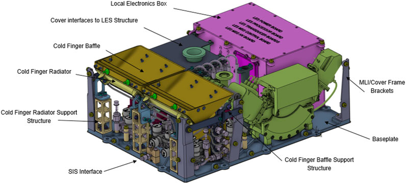
Figure 10. ProSPA Analytical Package Design (cover panels and MLI not shown). The spectrometers and their frontend electronics are accommodated close to the LES (pink) and are depicted in green (MSS) and dark grey (EGA/ITMS). GSS and GPS elements are accommodated between the two spectrometers and under the cold finger baffles.
The AP is connected to the SIS via a heated gas transfer pipe which leads to a hot manifold interconnecting various AP subassemblies. During operations, the temperature of hardware elements exposed to released volatiles is kept at ∼100°C–120 °C to prevent condensation. The hot manifold is part of the Gas Processing System (GPS) that is equipped with temperature and pressure sensors and is connected to 2 cold fingers (radiatively coupled to space to support accumulation of volatile species under temperature control, and used for removal or separation of volatiles via cryogenic methods), temperature-controlled Platinum-Carbon and Copper Oxide reactors, and a Getter vessel. Together, they support the physical and chemical processing of volatiles into species suitable for isotopic analysis. The manifold is also connected to an expansion volume, the Evolved Gas Analyzer (EGA, including an Ion Trap Mass Spectrometer), and a Magnetic Sector System (MSS, that includes a Magnetic Sector Mass Spectrometer). Both the EGA and MSS are connected to a Gas Supply System (GSS) that provides reactants and calibration gases in pressure vessels with a volume of 2 mL under pressures of up to 50 bar. They are connected via pulse controlled low throughput Piezo Valves (patented by the OU). Available consumables include CO2, a mixture of noble gases, N2, H2, and a CO/H2 mixture; these gases are used for calibration purposes, for supporting the gas analysis, and–in the case of H2–for the ISRU demonstration. The expansion volume and the spectrometers are connected to space via vent/exhaust openings that allow to purge these systems and allow analyzed volatiles to escape to space during or after spectrometer measurements.
After delivery of the sample to the SIS, sealing of the oven by the Tapping Station, establishing readiness of the AP for operation and conditioning of the hot manifold and gas transfer pipe to operational temperature, volatiles are extracted from the sample through heating the sealed oven in specific modes to accomplish a variety of analyses. In case of high amounts of volatiles in the sample, the expansion volume in the hot manifold can be used to sub-divide the quantity of released volatiles by the volume ratio of manifold and expansion volume. Depending on the intended investigation, the sample or sample gas can be processed using cold fingers, reactors, or a getter vessel, before the resulting gas is routed to the spectrometers. After analysis, the gases leave the spectrometers into the vacuum of space through the exhausts.
The main analysis techniques supported by ProSPA are Evolved Gas Analysis (EGA) and Stepped Pyrolysis or Combustion. For EGA, the sample temperature is increased steadily at a constant rate of ca. 6 K/min. Volatile molecules enter the EGA manifold and are routed to the ITMS sensor compartment directly or via a capillary depending on the gas pressure. In the ITMS sensor neutral species may be ionized through interaction with a beam of electrons released by thermionic emission from a resistively heated wire filament. Ions are trapped within the specifically configured electric field and are ejected towards an electron multiplier detector in order of increasing mass-to-charge (m/z) ratio. The output of the detector as a function of time constitutes a mass spectrum and is reported as part of science telemetry. In addition to analysis of inorganic species, the ITMS also provides operational modes which support the analysis of organic compounds via their molecular fragments.
For stepped pyrolysis/combustion, volatiles are released from the sample in a sequence of fixed temperature steps in vacuum or in presence of supplied oxygen. Data on released gases is collected for a typical duration of 30 min at each step. The resulting sample gas can then be routed to the Magnetic Sector System. The core sub-system of the MSS is the Magnetic Sector Mass Spectrometer which allows measurements of isotope ratios. In order to achieve good isotopic measurements over a range of sample sizes the instrument can operate in two modes: dynamic and static. In dynamic mode the mass spectrometer’s exhaust is open to space (via the associated gate valve). Sample and reference gases from the GPS enter a change-over valve through capillary leaks which switches one of the gases into the mass spectrometer whilst the other leaks into vacuum. Switching the change-over valve switches the gases which are entering the mass spectrometer and vacuum, thus allowing rapid comparison between the sample and reference gases. This measurement approach allows good isotopic precision (∼0.1‰) but requires μmol quantities of sample gas. In static mode, the mass spectrometer is sealed by closing the gate valve and the entire sample enters the mass spectrometer for analysis. Following analysis, the mass spectrometer is evacuated, and the procedure repeated for the reference gas. Since practically the entire sample gas enters the mass spectrometer and is available to be ionized and analyzed for a long period of time, static analysis gives the greatest sensitivity (∼nmol quantities of sample gas). However, this comes at the cost of reduced isotope precision (∼1‰) as the gas pressure reduces during the analysis and it is not possible to make a contemporaneous comparison with the reference gas. Furthermore, static analysis is only suitable for gases which are not modified (destroyed or chemically changed) by being in contact with the hot electron emitter filament. Therefore, only species such as noble gases, CO2, CO, N2 and CH4 are suitable for static analysis.
The choice of using either dynamic or static analysis method depends on the type of gas sample, the available quantity of sample gas, and the desired accuracy and sensitivity for the intended investigation.
Table 3 shows the basic characteristics of the ProSPA AP mass spectrometers and the measurement requirements applicable for these instruments.
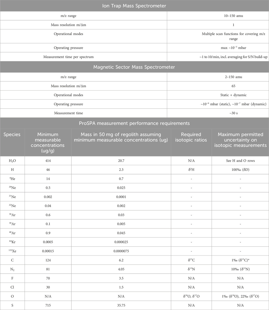
Table 3. ProSPA mass spectrometer characteristics and measurement performance requirements.
The demonstration of in-situ Resource Utilization (ISRU) assumes the presence of oxygen-bearing minerals such as Ilmenite (FeTiO3) in the sample and has been successfully demonstrated in the laboratory (Sargeant et al., 2020). The sample is reduced by exposing it to a suitable reactant, and heated to temperatures of ∼900°C–1,000 °C. In ProSPA, the supplied reactant is H2 which is stored in the GPS. For the ISRU demonstration, a suitable quantity is supplied to the hot manifold and sample gas pipe to expose the sample. The oven is then heated close to maximum temperature (950 °C) for several hours, and the resulting water vapor is trapped via a cold finger. Once the reaction phase is complete, the trapped gas is analyzed via the EGA subsystem.
The ISRU demonstration can be performed on a sample that has already been analyzed before, so it does not require use of a precious pristine sample. In fact, a completely outgassed sample is desired for performing the ISRU demonstration, as volatiles and mineral decomposition products could negatively impact the reduction process (limited water extraction yield) or complicate the interpretation of the gas products. Depending on the mission lifetime and available resources, the demonstration may only be performed on a small number of samples due to the time and energy required.
2.6 PROSPECT experimental concept validation
The general design concept of the PROSPECT package has been tested and validated ahead of the PROSPECT CDR via a series of experimental test campaigns that encompassed all key subassemblies.
For ProSEED, a Demonstration Model (DM) has been built and tested successfully in representative materials in a cryogenic environment. Gas concrete, brick layers, and mixtures of NU-LHT-2M lunar regolith simulant, small rocky inclusions and water (up to a water ice content of ∼10 wt%) have been drilled successfully up to a depth of 1 m at temperatures down to < -150°C, followed by cryogenic sample acquisition and sample delivery to representative hardware. All robotic elements (PRJ, DTJ, mandrel, sampling mechanisms) have been experimentally proven in that setup. HDRM prototypes have been tested separately. A flight-like ProSEED imaging system model has been built and demonstrated multispectral imaging and video capability on targets including rock samples. It also successfully passed a thermal test campaign that included exposure to temperatures as low as −100 °C. Testing of the permittivity sensor has been explained in section 2.4.4. and (Trautner et al., 2021b).
For ProSPA, a Bench Development Model (BDM) has been assembled and used to execute the key sample processing and analysis steps foreseen to be performed by ProSPA. Oven models, valve prototypes, reactor vessel and other key hardware have been tested in this setup and also separately for proofing their key performances. Development models of the ITMS and magnetic sector spectrometers have been assembled and tested with prototype electronics in support of finalizing the flight designs. An ITMS sensor and related flight electronics that are closely resembling the ProSPA design have been developed for the EMS spectrometer (Trautner et al., 2021b) and successfully tested in space during the Astrobotic M1 lunar mission. For the SIS, lower-level prototypes and a flight-like Engineering Model (EM) have been assembled and tested for proofing the concepts and for supporting the development of the final flight design. Figure 11 shows a number of PROSPECT hardware elements that were utilized for the experimental concept validation.
Once the PROSPECT qualification hardware is assembled, it will be used to execute flight-like operations in representative environments and for proving the compliance to all PROSPECT performance requirements. The data acquired during these test campaigns will enable further publications on the detailed performances of the robotic and scientific performances of the PROSPECT flight design and its subassemblies. The present paper is intended to serve as an anchor point for future publications on test results and on the results of the actual PROSPECT mission as part of the CP-22 lander payload.
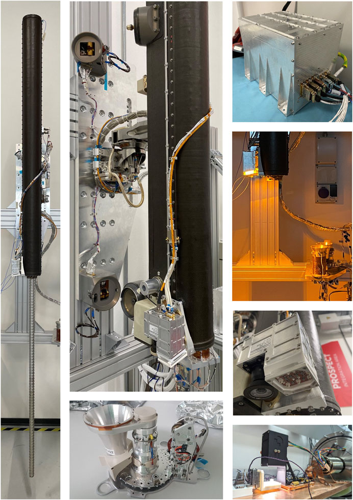
Figure 11. PROSPECT Engineering Model (EM) hardware. Left: ProSEED drill box with fully extended drill rod. Center top: ProSEED drill box including Imaging System, mechanical interface elements (PRJ, EHDMs) and harness in fully functional configuration. Center bottom: SIS EM during assembly, showing alignment collet, Tapping Station, and carousel with first oven installed. Right bottom: SIS SamCam during a calibration campaign. Right top: ProSEED CEU. Right center (2 images): ProSEED Imaging System; the 630 nm LEDs are activated in the upper image.
3 PROSPECT operations planning
The operations planning for the PROSPECT package is highly dependent on the constraints posed by the target mission. For missions that support lunar night survival a very flexible operations approach that fully exploits all capabilities of the various instruments can be employed, and a cautious operations plan that retires operational risks step by step can be supported. For short-lived missions that span only a single lunar day, a highly automated approach using a more modest number of pre-validated operations sequences is advisable. This allows to maximize the number of samples that can be acquired and processed within the short mission lifetime but reduces operational flexibility and implies acceptance of higher operational risk. In the following chapters we present our baseline approach for the more challenging short-lived mission type. This should be understood as a baseline concept that needs to be adapted to an actual set of mission constraints.
3.1 Mission constraints
The baseline assumptions for a lunar polar landing site without lander night survival include the availability of a 10 Earth-day long window for spacecraft surface operations between landing and nightfall. This timeframe typically includes vehicle post-landing checks, propulsion system passivation, initial battery charging, payload commissioning and operations, as well as system safeing and lander passivation before lunar night. Payload operations are therefore expected to face significant constraints in terms of available resources. In addition to limitations on time, power and energy available to payloads, the spacecraft also imposes constraints on data rates and data volumes for commanding and telemetry downlink. An efficient planning of coordinated payload operations and resource utilization is therefore paramount for optimizing mission success and for maximizing the scientific return. The following paragraphs summarize the key PROSPECT operations phases and their specific requirements; the related resource requirements are provided in Table 4.
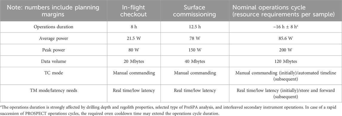
Table 4. PROSPECT operations resource requirements.
3.2 Checkout and commissioning activities
The possibilities for checkouts of payload systems during cruise are usually constrained; typically, limited functional checks will be conducted during transfer and/or in lunar orbit. Among the desirable checkout activities for PROSPECT are thorough functional checks of the electronics systems (CEU and LES) and operations of the ProSEED sensors and instrumentation, as well as activation of the ProSPA spectrometers. The goal is to confirm nominal function of all systems that do not depend on electromechanical or deployment systems to confirm their nominal condition after launch, and – for ProSPA - to obtain a first assessment of instrument signal background and spacecraft outgassing levels, which are important factors for subsequent science data analysis.
After landing, the successful commissioning of the PROSPECT package is a necessary pre-requisite for executing the science mission. Commissioning will include the same functional checks performed during cruise; however, in addition all deployment means (internal and external HDMs) will be activated and all mechanisms will be moved through their kinematic envelope as far as feasible without active drilling. During the execution of these functional checks, sensors and instrumentation will be employed as needed for acquiring data that supports the selection of the most suitable command sequences for initial operations. For ProSEED, this will include acquisition of multispectral images of the drill working area, images of the IS calibration target, images supporting the verification of post-landing drill-SIS alignment, calibration/noise level measurements for the permittivity sensor, and acquisition of environmental data including level of straylight and subsystem temperatures. The imagery will also allow to assess the level of dust deposition during the landing event. This data will be used for assessing the general situation and geology of the landing site, selecting the first drilling location, adjusting the IS exposure time, adjusting durations of mechanism warmup periods, and for selection of permittivity sensor measurement duration. For ProSPA, repeating the ProSPA spectrometer checkouts performed in orbit will provide information on the evolution of spacecraft outgassing after the cruise checkout, and on contamination from landing phase combustion products and from vented fuel. A bakeout of the AP, performed with activated spectrometers, will gradually reduce the background level caused by the presence of contaminants within the laboratory manifolds and allow to characterize the residual background. The SIS will be commissioned by releasing the carousel launch lock, actuation of the carousel and TS mechanisms, and taking images of the SamCam calibration target. Once bakeout is completed, resources permitting, an empty oven (called a “blank”) may be imaged, rotated to the TS and sealed. The blank is then processed using a default analysis sequence in support of system calibration and further background characterization. Commissioning of PROSPECT is complete as soon as the nominal function of all systems, sensors, instruments, and mechanisms has been confirmed, and all data necessary for selecting and adjusting the command sequences for initial nominal operations has been obtained.
3.3 Nominal PROSPECT operations
After successful commissioning, nominal operations can commence. While the basic sequence of activities for PROSPECT is well established, the lander platform and mission design including related constraints (power and energy availability, communication architecture and uplink/downlink windows, link latency and bandwidth, illumination and thermal conditions at the landing site and specifically in the drill working area) have a significant impact on the sequencing and timing of PROSPECT operations. For these reasons the operations concept presented here must be seen as a template that needs to be adapted to a specific mission environment.
After power is applied to PROSPECT, first housekeeping data and a boot report are generated and transmitted to the lander as part of essential telemetry. After loading the application software, PROSPECT is ready for executing ad hoc or pre-validated operations sequences. Initial activities typically include the warmup of mechanisms and other subsystems (IS) to bring them above minimal operational temperature and allow their engagement without delay via nominal operations command sequences. At least during initial operations, operator checkpoints are maintained for checking the boot report, for confirming the successful completion of the warmup phase, and for other points where operational risks need to be assessed. The first drilling location is pre-selected based on images acquired during the commissioning phase, and drilling is initiated in either power-limited, force limited, or constant speed mode. During drilling, depending on available resources, the drill may be stopped periodically (typically every few cm drilling depth) to allow the IS to acquire multispectral images of the drill cuttings. At depths beyond 40cm, the permittivity sensor is engaged after the IS before resuming the drilling activity. The depth for acquisition of the first sample depends on the scientific context of the landing site but is generally expected to be from a shallow depth that is deep enough to avoid the surface contaminants deposited by the spacecraft and landing process (combustion products, vented fuel, outgassing products). Subsequent samples are then expected to be acquired from multiple depths down to the maximum depth of 100 cm (ref. Table 1), adding up to a complete vertical survey. Before a sample is acquired, the drilling activity is stopped in order to allow the sampling tool to cool down for a typical period of 10–20 min. This allows to reduce the volatile loss during sample acquisition.
The ProSPA package is initialized at a suitable time after ProSEED power-up and before sample acquisition by ProSEED. As for ProSEED, boot software and application software are loaded, automatic checks are performed, and their results are reported in essential telemetry. SIS systems and mechanisms are warmed up, the selected oven is placed below the sample delivery position, and the system awaits the start of the sample transfer procedure.
For sample acquisition, ProSEED first implements a partial (few mm) retraction of the drill rod within the borehole and then extends the sampling tool’s push tube and proceeds to drill to a depth that ensures the push tube is filled to an adequate level. The sample is not actively retained in the push tube but is held in place by adhesion and friction forces. After acquisition, the sample is extracted from the drill hole, rotated over to the SIS, and the sample transfer procedure commences. The drill (via the PRJ) and the SIS (via the DOF of the alignment device) have degrees of freedom that are approximately orthogonal at the sample delivery position, and a software-controlled alignment procedure ensures the correct position of the ProSEED drill and simultaneous position of the target oven at the sample delivery position in the SIS. The sample is transferred via simultaneous downward movement of the drill rod and retraction of the push tube, leading to the discharge of the sample (which may be in solid or fractured form) into the oven.
After sample transfer, the target oven is first rotated under the SamCam, where multispectral and 3D images are acquired before the oven is positioned under the TS and the oven is sealed.
The ProSEED drill is then retracted to clear the alignment device and rotated back to the drill’s default position. On some occasions, the movement may be stopped after clearing the SIS for taking multispectral images of the IS calibration target that is accommodated at the base of the SIS. The drill is then stowed, outside the FOV of the SIS radiator, until the next sample acquisition is initiated.
After the sample is sealed in the ProSPA oven, volatile extraction and analysis can commence, a process expected to take several hours depending on the chosen analysis method. During this process, the carousel and SIS temperatures increase because of the energy spent heating the oven. As the conductive coupling of the SIS to the environment is minimized by design to allow nominal operation also in a warm interface environment, cooling of the SIS after an extraction process happens almost exclusively via radiative cooling. This results in an important operational constraint and highlights the importance of the thermal interface design aspects for enabling efficient operations.
The bulk of the data volume generated by PROSPECT consists of science data. After generation by the instruments and compression by the ProSEED CEU this data can be released for transmission by telecommand. Data processing, compression and the bulk of the data transmission is typically performed while ProSPA is processing the acquired sample. This allows to power down the PROSPECT package soon after completion of the sample analysis by ProSPA.
4 Summary and conclusion
PROSPECT is a comprehensive payload package for subsurface sample acquisition and analysis of volatiles and other gases in lunar environments including polar areas. It includes the ProSEED drill, capable of acquiring samples from up to 1 m depth, and the ProSPA instrument which is dedicated to the extraction and analysis of volatiles from acquired samples. ProSEED also includes a multispectral imager, a subsurface permittivity sensor, and a set of additional sensors for acquisition of engineering and auxiliary data. ProSPA includes an analytical laboratory and two mass spectrometers, as well as a multispectral sample imager. PROSPECT supports vertical surveys at multiple drilling locations within its working area. The ProSPA instrument is capable of extracting volatiles from samples via heating and supports volatile analysis with respect to molecular species and isotopic composition. The built-in capabilities of the analytical laboratory for volatile storage, separation and processing further enhance the package’s capabilities. ProSPA is also capable to demonstrate the thermal-chemical reduction of a sample with hydrogen to produce water/oxygen as a first in-situ small-scale proof of concept for ISRU processes. The PROSPECT package provides some flexibility for accommodation of its subunits on different types of landers and is compatible with mission durations of 1 lunar day or more. PROSPECT has been selected as a key payload for the CP-22 mission of NASA’s Commercial Lunar Payload Services program and is expected to significantly enhance the understanding of the distribution, origin and behaviour of volatiles in lunar polar areas.
Data availability statement
The datasets presented in this article are not readily available because underlying designs and data are the Intellectual Property of ESA and ESA’s industrial and academic contractors. Requests to access the datasets should be directed toUm9sYW5kLlRyYXV0bmVyQGVzYS5pbnQ=.
Author contributions
RT: Investigation, Supervision, Writing–original draft, Conceptualization, Project administration, Visualization, Funding acquisition, Methodology. SB: Conceptualization, Investigation, Project administration, Writing–review and editing, Supervision, Methodology, Visualization, Formal Analysis. RF: Conceptualization, Project administration, Supervision, Writing–review and editing, Funding acquisition, Methodology. DH: Investigation, Methodology, Supervision, Writing–review and editing, Validation. BH: Project administration, Resources, Supervision, Writing–review and editing, Funding acquisition. CH: Conceptualization, Project administration, Software, Supervision, Writing–review and editing, Methodology. SI: Supervision, Validation, Writing–review and editing. ML: Conceptualization, Investigation, Methodology, Project administration, Supervision, Writing–review and editing, Visualization. AMa: Conceptualization, Project administration, Visualization, Writing–review and editing. GM: Project administration, Supervision, Writing–review and editing. NM: Conceptualization, Investigation, Methodology, Project administration, Visualization, Writing–review and editing. CP: Conceptualization, Project administration, Visualization, Writing–review and editing, Supervision. PR: Conceptualization, Investigation, Methodology, Validation, Writing–review and editing. AR: Conceptualization, Project administration, Supervision, Writing–review and editing. FA: Formal Analysis, Investigation, Methodology, Validation, Writing–review and editing. NC: Project administration, Writing–review and editing. HC: Methodology, Validation, Writing–review and editing. CG: Conceptualization, Formal Analysis, Methodology, Writing–review and editing. PL: Investigation, Methodology, Writing–review and editing. RL: Methodology, Project administration, Supervision, Writing–review and editing. AMo: Conceptualization, Investigation, Methodology, Validation, Writing–review and editing. JM: Investigation, Methodology, Validation, Writing–review and editing. LN: Software, Supervision, Writing–review and editing. PP: Conceptualization, Methodology, Writing–review and editing. SS: Conceptualization, Investigation, Methodology, Validation, Writing–review and editing. AV: Investigation, Methodology, Validation, Writing–review and editing.
Funding
The author(s) declare financial support was received for the research, authorship, and/or publication of this article. The development of PROSPECT is funded by the European Space Agency ESA.
Acknowledgments
The authors would like to acknowledge significant project contributions from the following entities and individuals: European Space Agency—S. Boazman (landing site analysis), J. Carpenter (phase A/B studies), C. Delepaut and T. Szewcyzc (electronics), E. Koekkoek (structures), K. Lundmark and G. Corocher (EEE components and electronics assembly), P. Hager (thermal design), M. Poizat (radiation environment), C. Paul and L. Gaillard (mechanisms), R. Kroll (harness), C. Mooney (cleanliness and contamination), E. Sefton-Nash (science), J. F. Salgado, H. Stier and F. Frost (software), L. Santos (FPGAs), J. Wolf (EMC), and other ESA TEC support team members; Leonardo S.p.A.—A. Ampolo Rella and P. Bologna (software), M. Fani (thermo-mechanical analysis), S. Feraboli (structural analysis), A. Scudiero (electronics system engineering), S. Campadelli (electronics), M. Peruzzotti (thermo-mechanical design), G. Scarcia (system engineering), E. Tella (thermo-mechanical design), G. Zocchi (thermo-mechanical engineering), A. Zamboni (phase A/B project management); Kayser Italia—R. Nartallo (system engineering), H. Nasimi (electronics), S. Pellari (structures), M. Verna (product assurance); The Open University external experts—D. Yau (mechanical design), J. Sykes (MSS design), J. J. Cooper (ovens and specialist manufacturing); Max Planck Institute for Solar System Research - R. Gerhardy, F. Goesmann, S. J. Knierim, O. Roders, J. Zelmer (all TS design and development); Airbus Defense and Space–A. Briggs (system engineering), A. Kiley (thermal design), S. Morgan (thermal design); DIAL–Anthony Evagora (SamCam engineering); RAL Space/STFC—E. M. Butroid (electronics), S. Hall, A. Hellstenius, C. Kellett and J. Mayers (software), T. Morse (electronics and systems engineering), S. Woodward (FPGA design); TUM—L. Grill (volatile preservation and extraction); Beyond Gravity—A. Schiaffini (project management), F. Urbinati (system engineering); Maxon–N. Steinert (project management); Sener—J. C. Bahillo (system engineering), F. del Campo (project management). Furthermore, the authors would like to thank the members of the PROSPECT science team and all those individuals not listed individually but who have supported the project in technical, administrative, managerial, and other domains.
Conflict of interest
Authors AMa and PP were employed by Kayser Italia S.r.L. Authors GM, CP, and AR were employed by Leonardo S.p.A. Author NM was employed by Dynamic Imaging Analytics Ltd.
The remaining authors declare that the research was conducted in the absence of any commercial or financial relationships that could be construed as a potential conflict of interest.
Publisher’s note
All claims expressed in this article are solely those of the authors and do not necessarily represent those of their affiliated organizations, or those of the publisher, the editors and the reviewers. Any product that may be evaluated in this article, or claim that may be made by its manufacturer, is not guaranteed or endorsed by the publisher.
References
Barber, S. J., Wright, I. P., Abernethy, F., Anand, M., Dewar, K. R., Hodges, M., et al. (2018). “ProSPA: analysis of lunar polar volatiles and ISRU demonstration on the moon,” in Lunar and Planetary Science Conference, Abs. 2172, The Woodlands, TX 77380, United States, March, 2018.
Colaprete, A., Schultz, P., Heldmann, J., Wooden, D., Shirley, M., Ennico, K., et al. (2010). Detection of water in the LCROSS ejecta plume. Science 330 (6003), 463–468. doi:10.1126/science.1186986
King, O., Warren, T., Bowles, N., Sefton-Nash, E., Fisackerly, R., and Trautner, R. (2020). The Oxford 3D thermophysical model with application to PROSPECT/Luna 27 study landing sites. Science 182, 104790. 104790. doi:10.1016/j.pss.2019.104790
Mortimer, J., Lécuyer, C., Fourel, F., and Carpenter, J. (2018). D/H fractionation during sublimation of water ice at low temperatures into a vacuum. Planet. Space Sci. 158, 25–33. ISSN 0032-0633. doi:10.1016/j.pss.2018.05.010
Murray, N. J., Evagora, A. M., Murray, S. Y., Barber, S. J., Mortimer, J. I., and Martin, D. J. P. (2020). “SamCam for the ESA PROSPECT lunar volatiles prospecting package; and a new family of miniature 3D multispectral cameras for space exploration,” in Lunar and Planetary Science Conference, Abs. 1918, The Woodlands, TX 77380, United States, March, 2020.
Paige, D., Siegler, M. A., Zhang, J. A., Hayne, P. O., Foote, E. J., Bennett, K. A., et al. (2010). Diviner lunar radiometer observations of cold traps in the moon’s south polar region. Science 330 (6003), 479–482. doi:10.1126/science.1187726
Pieters, C., Goswami, J. N., Clark, R. N., Annadurai, M., Boardman, J., Buratti, B., et al. (2009). Character and spatial distribution of OH/H2O on the surface of the moon seen by M3 on chandrayaan-1. Science 326 (5952), 568–572. doi:10.1126/science.1178658
Sargeant, H. M., Abernethy, F., Barber, S., Wright, I., Anand, M., Sheridan, S., et al. (2020). Hydrogen reduction of ilmenite: towards an in situ resource utilization demonstration on the surface of the moon. Planet. Space Sci. 180, 104751. doi:10.1016/j.pss.2019.104751
Trautner, R., Barber, S. J., Carpenter, J., Fisackerly, R., Houdou, B., Leese, M., et al. (2018). “Prospect: a novel package for subsurface sample acquisition and analysis of lunar volatiles,” in Proceedings of the International Astronautical Congress, IAC-18, Bremen, Germany, October, 2018.
Trautner, R., Barber, S., Leese, M., Howe, C., Morse, T., Cohen, B. A., et al. (2021b). “EMS: fast track development of a miniaturized mass spectrometer for lunar applications,” in Proceedings of the International Astronautical Congress, IAC-21,A3,2A,x62020, Dubai, United Arab Emirates, October, 2021.
Trautner, R., Reiss, P., and Kargl, G. (2021a). A drill-integrated miniaturized device for detecting ice in lunar regolith: the PROSPECT permittivity sensor. Meas. Sci. Technol. 32, 125117. doi:10.1088/1361-6501/ac261a
Keywords: prospect, lunar drill, lunar volatiles, sample analysis, mass spectrometry, multispectral imaging, permittivity sensor
Citation: Trautner R, Barber SJ, Fisackerly R, Heather D, Houdou B, Howe C, Iacobellis S, Leese M, Mariani A, Meogrossi G, Murray N, Panza C, Reiss P, Rusconi A, Abernethy F, Cann N, Chinnery H, Gscheidle C, Landsberg P, Lindner R, Morse AD, Mortimer J, Nicolae L, Picchi P, Sheridan S and Verchovsky A (2024) PROSPECT: A comprehensive sample acquisition and analysis package for lunar science and exploration. Front. Space Technol. 5:1331828. doi: 10.3389/frspt.2024.1331828
Received: 01 November 2023; Accepted: 19 February 2024;
Published: 03 April 2024.
Edited by:
Joseph N. Pelton, International Space University, United StatesReviewed by:
Jerry Stone, Spaceflight UK, United KingdomZhiping He, Chinese Academy of Sciences (CAS), China
Copyright © 2024 Trautner, Barber, Fisackerly, Heather, Houdou, Howe, Iacobellis, Leese, Mariani, Meogrossi, Murray, Panza, Reiss, Rusconi, Abernethy, Cann, Chinnery, Gscheidle, Landsberg, Lindner, Morse, Mortimer, Nicolae, Picchi, Sheridan and Verchovsky. This is an open-access article distributed under the terms of the Creative Commons Attribution License (CC BY). The use, distribution or reproduction in other forums is permitted, provided the original author(s) and the copyright owner(s) are credited and that the original publication in this journal is cited, in accordance with accepted academic practice. No use, distribution or reproduction is permitted which does not comply with these terms.
*Correspondence: R. Trautner, Um9sYW5kLlRyYXV0bmVyQGVzYS5pbnQ=