 Laurine Hillion
 Jean-Denis Parisse1*
- 1Centre de recherche de l’école de l’air (CREA), Ecole de l’air et de l’Espace, Salon-de-provence, France
- 2Hybrid Propulsion for Space, Bordeaux, France
This study investigates the feasibility and performance of a missile propelled by a Hybrid Rocket-Based Combined Cycle (HRBCC) engine, which combines hybrid rocket and air-breathing engines. The HRBCC engine could enable intra and extra-atmospheric hypersonic flight in the future. Using a hybrid rocket engine could bring several advantages as reduced costs, increased reliability and simplicity. This research presents the unique feature of the hybrid rocket engine developed by HyPrSpace and explains its benefits for the conception of a HRBCC system. The performance of the missile was studied in two operational modes: pure rocket and ramjet. The results were then used to develop an in-house code that compared the trajectory of different missiles. Our findings indicate that HRBCC engines provide several advantages over other propulsive technologies and can meet the requirements of various military applications.
1 Introduction
Although multi-stage launchers remain the primary means of space transportation, the cost of their production have continued to rise (Munoz, 2011). To address this issue, engineers are developing reusable launchers, with the rocket-based combined cycle (RBCC) engine emerging as a promising technology for reusable single-stage to orbit (SSTO), two-stage to orbit (TSTO) launchers, and hypersonic vehicles (Zhangtian et al., 2019; Zhang et al., 2020; Rui et al., 2021). The RBCC engine combines several propulsion systems which operate continuously without interrupting the propulsion in a very large range of speed. The propulsion systems combined usually includes a ramjet, a scramjet, and a liquid rocket engine, enabling a multimodal operation. From take-off to Mach 2, the engine operates in ejector mode, followed by ramjet mode from Mach 2 to Mach 5, scramjet mode from Mach 5, and pure rocket mode at atmospheric exit. By combining several engines into one single system, RBCC engines offer an efficient and versatile solution for propulsion, which may help to reduce the cost of space exploration.
Even if the RBCC engine has been studied for several years, its development is hindered by technical obstacles, like the engine’s ejector mode and its difficulty to produce enough thrust for an efficient acceleration (Zhangtian et al., 2019). Currently, the most advanced RBCC engine in development is the Synergetic Air-Breathing Rocket Engine (SABRE) by Reaction Engines Limited, designed to power the reusable SKYLON SSTO (Aggarwal et al., 2015; Davies et al., 2015). While SABRE has the potential to revolutionize hypersonic and suborbital flight, like most RBCC engines, it relies on a liquid rocket engine, which can be complex, requires a large volume of fuel, and raises safety concerns associated with the storage of oxidants. With the development of new technologies, it is interesting to explore alternative propulsion systems, such as hybrid rocket engines. Hybrid RBCC (HRBCC) engines offer a number of advantages that include reduced costs, increased reliability, and greater operational flexibility. While RBCC engines have been studied for several years, only a few studies have explored the use of hybrid rockets in this context. In 2013, Chang et al. (2018) presented the first concept of a HRBCC propulsion system, which featured a hybrid rocket engine embedded in the ramjet/scramjet duct, similar to other RBCC engines.
However, this work proposes a new design concept for the HRBCC system where the rocket and air-breathing engines share the same combustion chamber. Thus, this study aims to conduct a preliminary analysis of the performance benefits of this engine type, comparing it with solid engines. For simplicity, the HRBCC engine in this study operates in two modes: the pure rocket mode (from take-off to Mach 2) and the ramjet mode (from Mach 2 to total combustion of the propellant). These modes were chosen to simulate the operation of a missile engine.
The content of the paper is organized as follow: Section 2 formulates the interest of the HRBCC engine and discusses the unique features of the hybrid rocket used. Section 3 presents the comparative study. Section 4 describes the approach used to determine the performance of both pure rocket and ramjet modes. Finally, Section 5 introduces the results and engage a discussion on their implications.
2 Interest of the HRBCC engine
2.1 RBCC engine
Currently, no engine by itself is capable of providing both a high Thrust to Weight Ratio (TWR) and a large specific impulse across the entire Mach range (Murthy and Curran, 1991; Daines and Segal, 1998). As shown in Figure 1 (Zhangtian et al., 2019), air-breathing motors have a good specific impulse but are only functional over a limited Mach range. In contrast, rocket engines have the best TWR but a very low specific impulse over the entire Mach range. However, the RBCC engine has the potential to bridge this performance gap by combining air-breathing and rocket engines. It behaves as an augmented rocket from take-off to supersonic speed, a ramjet/scramjet in supersonic/hypersonic flight, and a pure rocket when the density of air becomes too low. This makes it possible to obtain an engine with both good TWR and specific impulse across the entire Mach range, all sharing roughly the same system hardware. Thus, the RBCC engine has the potential to propel single-stage launchers (SSTOs) and hypersonic vehicles.
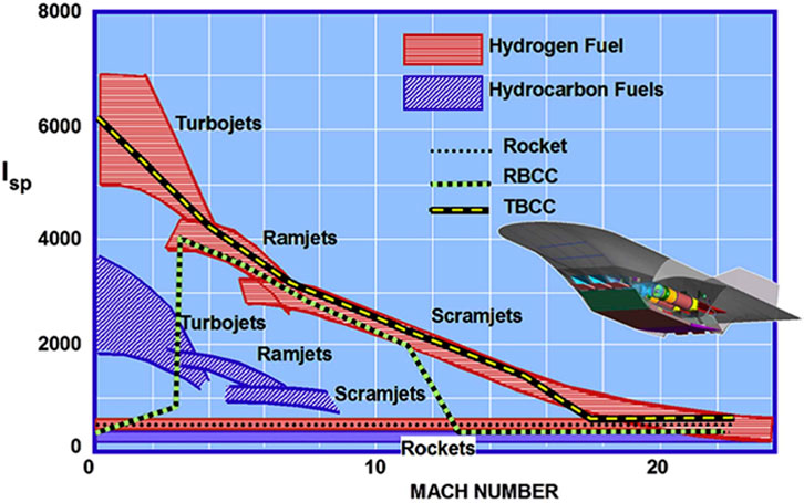
FIGURE 1. Specific impulse comparison for different type of propulsion. Reproduced from Foster et al. (2012).
RBCC engines offer a significant advantage for hypersonic missiles. They allow for increased efficiency, leading to longer ranges and the ability to strike targets that would otherwise be out of reach. They can also achieve even higher speeds than traditional rocket engines, making them more difficult to intercept and giving them a greater advantage in combat.
Even if the realization of single-stage launchers (SSTO) has always been a very attractive idea and the dream of many engineers, its propulsion by rocket engines alone makes its use very inefficient. According to (Escher, Hyde, Anderson), the propellant carried by an SSTO using rocket propulsion alone can represent up to 90% of the initial mass of the vehicle, leaving only 10% of the total mass for the rocket structure, electronics, and payload. However, RBCC engines, with their higher specific impulse, can reduce the propellant mass ratio from 90% to 70%. Thus, this type of engine could be a starting point for SSTO propulsion. However, as explained by Dorrington and Tec (1990), the mass of propellant on board is not the only figure of merit to consider, or even the most appropriate. The use of RBCC engines involves several drawbacks. Indeed, these engines are much heavier than rocket engines, they require larger volumes of propellant (structural stresses), and are subject to more severe conditions at the exit of the atmosphere (stresses on thermal protection).
Typically, RBCC engines rely on liquid rocket engines. Due to their ability to achieve the highest achievable specific impulses, their on-off and throttled operation and as a well-known technology, these engines appear to be the most natural solution for RBCC engines. However, liquid rocket engines are highly complex and subject to operational, safety, and environmental concerns. As an alternative to liquid rocket engines, hybrid propulsion is presented here. While hybrid propulsion was once known for its technological barriers, it is currently experiencing a strong revival due to its several advantages.
2.2 Hybrid propulsion
2.2.1 Definition
Rocket engines are typically classified based on the chemical state of their propellants. In a hybrid engine, the oxidizer is typically stored in liquid form in a tank, while the fuel is stored in solid form in the combustion chamber.
2.2.2 Advantages
Several works have already mentioned the various advantages and disadvantages of hybrid propulsion (Altman, 2003; Chiaverini and Kuo, 2007; Sutton and BIBLARZ, 2017; Ruffin, 2018; Palateerdham et al., 2020) summarized below:
2.2.2.1 Thrust modulation
Thrust can be modulated by controlling the oxidizer flow in a much simpler way than for a liquid engine, which requires synchronization of two propellant flows. This feature makes the engine easily adaptable to a wide range of missions.
2.2.2.2 Low cost
The total cost for hybrid systems is advantageous compared to its safety features and inert propellant. Since its manufacture does not require large structures, the fuel plant can be located near the launch site. In addition, the system can tolerate larger design margins, resulting in lower manufacturing costs.
2.2.2.3 Grain robustness
Unlike solid engines, grain cracks or flaws are not catastrophic as the propellant is inert. On the contrary, cracks in the grain of solid engines have the effect of increasing the wet surface and thus increasing the pressure in the chamber, beyond the design conditions.
2.2.2.4 Safety
Fuel is inert and can be manufactured, transported and handled safely. As the fuel and oxidizer are in different and separate phases, the chances of explosions are very low (“intimate” mixture between oxidizer and fuel almost impossible) and has very few failure modes.
2.2.2.5 Temperature sensitivity
Since the effect of temperature on the combustion rate is small, the variation in ambient temperature during launch has very little effect on the pressure in the combustion chamber. Thus, the worry about designing solid motors to achieve Maximum Expected Operating Pressure (MEOP) is greatly reduced.
2.2.2.6 Propellant versatility
The selection of propellant is much greater than for liquid or solid propulsion. Compared to liquid or solid engines, energetic metals can be added to the fuel to improve both performance and density without the need for abrasion.
2.2.2.7 Environmental friendliness
Several propellants used for the hybrid engine are environmentally friendly as the products and reactants are non-toxics.
2.2.3 Disadvantages
However, conventional hybrid engines have several disadvantages compared to their liquid and solid counterparts, which explains the lack of attention this propulsion system has received in the past.
2.2.3.1 Low regression rate
A larger burning area is required to attain the desired fuel mass flow from the grain in hybrid rockets. Non-etheless, the regression rate of hybrid fuel surfaces is considerably slower than that of solid fuels. This is due to the diffusive flame in hybrid fuels being more distant from the burning surface when compared to the conductive flame present in solid rocket engines.
2.2.3.2 Low combustion and mixing efficiency
In hybrid rockets, reactants are not intimately mixed or compelled to combine as they are in solids and liquids. Therefore, the performances are quite lower than the theoretical ones.
2.2.3.3 A difficulty to be usable for large scale engines
High thrust-to-weight ratios and specific impulse are critical metrics for measuring rocket engine performance, and achieving them presents a significant challenge for hybrid propulsion. This challenge is partly due to the lower energy density of the solid fuel used. While hybrid rocket engines have found utility in small-scale applications such as model rockets and experimental spacecraft, scaling up poses additional challenges. Indeed, in some hybrid configurations, the regression rate decreases as the motor is scaled up, ultimately resulting in a decrease in performance.
2.2.3.4 A variation in the mixing ratio O/F
During operation, the mixture ratio can vary and have a significant impact on the performance metrics, such as thrust and specific impulse. The inability to maintain the oxidizer-to-fuel ratio O/F at the optimal value during operation results in a loss of combustion efficiency.
2.2.4 HyPrSpace Technology
Hybrid Propulsion for Space, or HyPrSpace, is an innovative company that aims to overcome some of those existing technological barriers with its hybrid engine technology. Specializing in the development of hybrid engines, the company’s primary objective is to create cost-effective micro-launchers capable of sending small satellites into low Earth orbit. HyPrSpace’s unique engine design, as seen in Figure 2, features a pressurized tank placed inside the fuel block, unlike conventional hybrid engines. Two fuel blocks are inserted in the inner body, with the first block positioned against the tank and the second in contact with the engine’s external wall. The additional solid fuel element increases the burned surface area and, thus, improves the heat transfer into the solid fuel enhancing the regression rate. The central placement of the tank within the combustion chamber allows for a higher flow of oxidant, increasing the burned surface and compensating for the engine’s low regression rate. The post-combustion chamber ensures optimal combustion.
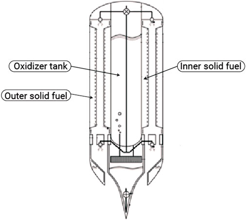
FIGURE 2. HyPrSpace’s engine.
Musa et al. (2019) proposed and investigated a novel combustion chamber design for a solid-fuel ramjet with a configuration very closed to HyPrSpace’s engine. In their configuration, they place a rod solid grain inside a tubular one. They found that this configuration improved the performances of the engine as well as its regression rate. These findings suggest that this configuration has the potential to improve the engine’s performance and could be applied to ramjet engines.
3 Comparative study and methodology
The objective of this study was to estimate the achievable performance of a HRBCC engine in comparison to a solid engine. The study involved a comparison of the performance of missiles powered by both types of engines and an analysis of the theoretical trajectory that each missile could reach. To this end, an in-house code was developed using a two-dimension trajectory model. In order to determine the trajectory reachable by the HRBCC engine, the performance of both the ramjet and pure rocket modes were evaluated. In the case of the pure rocket mode, an investigation was conducted on the choice of propellant to determine the theoretical maximum performance that could be achieved. Furthermore, a thermodynamic study of the ramjet mode, analyzing each process of the thermodynamic cycle, namely, compression, combustion, and expansion.
3.1 Missiles characteristics
To determine the suitability of HRBCC engines for various missile types, a comparison of the performance of solid and HRBCC engines was conducted. Three categories of missiles, based on their weight (light, medium, and heavy), were examined. Their characteristics are summarized in Table 1. These characteristics were used to calculate the missile’s performance assuming both engine types had the same features (diameter, mass, and thrust) and were launched under identical conditions (launch angle and initial velocity).
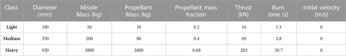
TABLE 1. Missile’s characteristics according to their weight class.
The propulsive performance of the missiles is defined by simply specifying the following two parameters.
• The propellant mass fraction, noted
• The specific impulse,
Where
3.2 Hypothesis
In order to give a first estimation of the performance achievable by the RBCC engine, an in-house code has been implemented to determine the trajectory of a missile powered by an RBCC engine. For the determination of the trajectory, several assumptions were taken into account.
• The Earth is flat and motionless.
• The calculation is based on a two-dimension oblique flight model in the pitch plane.
• A windless and unaffected flight is considered, with the longitudinal axis of the vehicle parallel to the trajectory at all times.
• The vehicle is launched from an inclined launch pad of 45°.
• Only two modes are used for the RBCC engine: pure rocket mode (from take-off to Mach two) and ramjet mode (from Mach two until total fuel consumption).
4 Performances study
4.1 Proposed design
Figure 3A Yang et al. (2015) shows the classical configuration of an RBCC engine which consist of a rocket, inlet, mixing duct, combustor and nozzle. Here, the rocket is embedded in the duct. In Figure 3A, the RBCC engine is represented in an ejector mode. In this mode, the inlet is open and the primary flow generated by the rocket engine entrain the airflow into the mixing duct. The fuel is injected in the combustor chamber, where it is mixed and burned with the primary and secondary flux. Figure 3B shows the schematic of the new design proposed for an HRBCC engine. The propulsion subsystems are integrated into a single engine with only one flow path: the air inlet, combustion chamber, and nozzle. The air intake is axisymmetric, and a duct connects it to the combustion chamber. Because the air-breathing and rocket engines share the same combustion chamber, this engine is smaller than a classical RBCC engine. The combustion chamber has two solid fuel grains, and the oxidizer tank is placed at the center, to simulate the configuration of HyPrSpace’s technology. Furthermore, the engine’s configuration allows for an easy integration of an aerospike nozzle, which offers attractive features like altitude compensation or a lighter and simpler design. However, these nozzles are not widely used principally due to the difficulty of cooling down their larger base aera.

FIGURE 3. RBCC configuration. Reproduced from Yang et al. (2023), with permission from Elsevier.
4.2 Pure rocket mode
To determine certain characteristics of the combustion products specific to the chosen propellant pair, the Chemical Equilibrium Application (CEA) software developed by NASA (McBride SG, 1996) was used. This software enables to calculate key parameters such as the molecular mass (MW), the temperature of the combustion chamber
Where
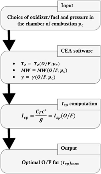
FIGURE 4. Flowchart of the numerical estimation.
For military missions, the performance parameter used was the volumetric specific impulse define by Eq. 4.2. This implies that, at equal specific impulse, a larger volumetric specific impulse would require a smaller volume of fuel. This is a significant advantage for missiles where having a compact design is critical.
4.3 Ramjet mode
The ramjet is one of the simplest engines since it consists only of an inlet, a diffuser, a combustion chamber and a nozzle [See Figure 5 (Zhang et al., 2015)]. It is considered to be the engine of choice for supersonic flights. Since it uses ambient atmospheric air, the ramjet does not require to carry an oxidizer tank on board. It thus offers a saving of weight and space to carry heavier payloads. However, despite their theoretical simplicity, this engine is not capable of propelling a stationary vehicle on its own. Thus, its application is limited and generally reserved to a military use. Unlike the ramjet from Figure 5, where the fuel is injected in the combustor in a liquid form (Liquid Fuel Ramjet or LFRJ), the ramjet studied here uses a solid fuel and operates as a Solid Fuel Ramjet or SFRJ, which is simpler than LFRJ as it avoids fuel-control, fuel-storage and the feed system (Krishnan and George, 1998). The thermodynamic study presented in the next parts relied on the stations described in Figure 5.
FIGURE 5. Ramjet schematic showing station numbering used for analysis. Reproduced from Zhang et al. (2023), with permission from Elsevier.
4.3.1 Thermodynamic cycle analysis
As ramjet performance decreases with increasing speed and altitude, a thermodynamic study was carried out to determine the ramjet performance under a wide range of flight conditions. Engine operation follows the Brayton cycle consisting of four main processes: Adiabatic compression in the air intake, isobaric combustion in the combustion chamber, adiabatic expansion in the nozzle and isobaric cooling in the atmosphere.
Based on an analysis of the thermodynamic cycle, it is possible to determine the specific thrust and specific impulse of the ramjet for different flight conditions, inlet pressure ratio (π) and air-fuel ratio (
Where the upstream flow velocity
4.3.1.1 Compression process
The supersonic inlet of a ramjet engine achieves compression through production of a series of shock waves. It is assumed that the losses across these shock waves represent the upper limit of its performance. Therefore, by determining the pressure losses, it is feasible to estimate the inlet’s performance. To gain insight into the critical role of geometry in the design of the inlet, an in-house code was employed to generate a supersonic inlet based on a chosen number of shock waves at a specific Mach number. The code relied on the Oswatitsch method (Oswatitsch, 1980) represented in Figure 6 (Heo et al., 2017).
FIGURE 6. Schematic of 2D external compression air intake.
The flow undergoes a transformation from supersonic to subsonic via
FIGURE 7. Diagram of the internal angles for the final normal shock.
FIGURE 8. Diagram of the internal angle for the ith oblique shock.
The pressure losses can be determined using the compression ratio π that refers to the amount of compression in the inlet. It is defined as the ratio of the static pressure at the outlet of the air intake to the static pressure of the upstream flow. It is possible to determine the influence of the Mach number and shockwave number on parameter π. During a cruise flight, the flow conditions (
With, for the oblique shocks:
And for the normal shock:
4.3.1.2 Combustion process
4.3.1.2.1 Temperature ratio
An energy balance of the combustion chamber (first law of thermodynamics) gives:
Where
The total temperature ratio τ is defined as:
Therefore, show the air-fuel ratio
So:
The total temperature ratio can hence be estimated for any value of the air-fuel ratio
4.3.1.2.2 Combustor exit mach number and pressure
As the combustion occurs at constant static pressure, the conservation of momentum applied to the chamber of combustion gives:
So, with a constant pressure, the kinetic energy is conserved. The application of the energy equation to the combustor gives:
Since combustion occurs at constant static pressure, we have
4.3.1.3 Expansion process
The expansion process in the nozzle is isentropic (so
Using Eq. 4.15, it is possible to express the temperature and the Mach at the nozzle exit:
The speed of sound at the nozzle exit is written:
Hence the speed at the nozzle exit:
It is therefore now possible to calculate the specific thrust of the ramjet.
Using the previous equations, the thrust and the specific impulse can be computed:
5 Results and discussion
5.1 General
In this section, the results of the performance analysis of both pure rocket and ramjet modes are presented. First, the performance of two oxidants,
5.2 Propellant performance
As it is illustrated in Figure 9, liquid oxygen
FIGURE 9. Volumetric Specific impulse vs. Mixture ratio.
FIGURE 10. Volumetric Specific impulse vs. Mixture Ratio.
From Figure 10, the optimal mixing ratio was chosen by selecting the maximum volumetric specific impulse, which was found at O/F = 5.5. For this specific mixture ratio, the specific impulse was determined and represented (green points) in Figure 9. Therefore, the specific impulse at sea level for the
Figure 11 shows the specific impulse as function of the altitude for both
FIGURE 11. Specific Impulse vs. Altitude.
5.3 Inlet performance and considerations
Based on the method described Section 4.3.1.1, an in-house code was developed to model the geometry of the inlet according to the number of shock waves and Mach number and represent their impact on the geometry design and performance. Figure 12 and Figure 13 display the results for three oblique shockwaves and one final normal shock (
FIGURE 12. Ramp profile for
FIGURE 13. Ramp profile for
As the Mach number increases, it is important to notice that the length and height of the inlet have to increase in order for the flow to be “started”. The flow is said to be started when the shockwaves are absorbed by the inlet. As explained by Heiser et al. (1994), this phenomenon is desirable since the inlet can capture as much air as possible, and because any normal shock waves that occur can be managed within the internal path flow. It is reminded here that a perfect gas model was used to determine the properties of the air over the system shockwave. However, this is not accurate especially at high speed and low altitudes where various physical phenomena (boundary layer-shockwave interaction, air dissociation) occur.
Figure 14 displays the variation of the compression ratio with the Mach number. The purple curve represents the ideal compression (isentropic compression) that would occur without any pressure losses. As the number of shockwaves increases, it is possible to reduce pressure losses. While increasing the number of shockwaves can help reduce pressure losses, this also requires a more complex inlet geometry. Additionally, generating a high number of shockwaves at low Mach numbers is not possible. To achieve very good compression ratios over the entire Mach range, the geometry of the inlet has to be variable. For the purposes of the study, it was considered that the air intake had a variable geometry and that only one oblique shock wave and one normal shock wave were generated. Thus, it is possible to determine the compression ratio π using the equation system from Eq 4.4 to Eq 4.6. However, by choosing to generate only one oblique shock wave at the air intake, the compression ratio will be very low, which will impact the performance of the engine.
FIGURE 14. Compression Ratio vs. Mach Number.
5.4 Results of the thermodynamic study
5.4.1 Compression
The properties of air across the supersonic inlet were calculated and plotted in Figure 15, Figure 16, and Figure 17 by using the system of equation from Eq. 3.2 to Eq. 3.3 The supersonic inlet generates two shock waves, and the Mach number of the flow at the inlet entrance is plotted as a function of the freestream Mach number in Figure 15. As the flow becomes subsonic due to the generation of the normal shock, the speed of the air at the entrance decreases with an increase in static temperature and pressure (as shown in Figure 16; Figure 17). This is explained by conservation of the energy: the deceleration of the flow implies a conversion of the kinetic energy to heat which leads to an increase of the static temperature and pressure. If more shockwaves were generated, the temperature and pressure would be higher which would impact the performances of the engine.
FIGURE 15. Mach number at the inlet after
FIGURE 16. Temperature at the inlet after
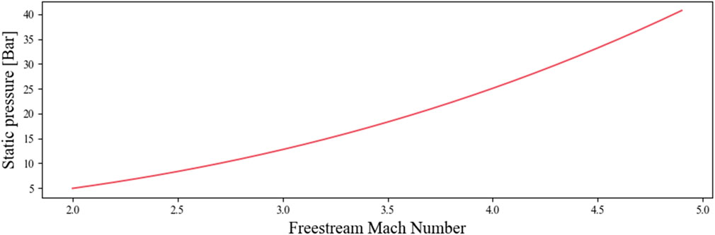
FIGURE 17. Pressure at the inlet after
5.4.2 Combustion
Figure 18 shows the impact of increasing the fuel-air ratio on the temperature in the combustion chamber. As the Mach number increases, the temperature rises rapidly. Some values of the air-fuel ratio result in temperatures capable of exceeding 3000 K, which is unbearable in practice. Yang et al. (2014) conducted a thermodynamic analysis were they considered the effect of the temperature limit on the performances of a scramjet. Zhang et al. (2015) extended this work and included the thermal choking boundary, which could, according to Daines and Segal (1998), bring mechanical simplification and weight reduction. While the current study does not consider these parameters, they should be considered when evaluating realistic design conditions.
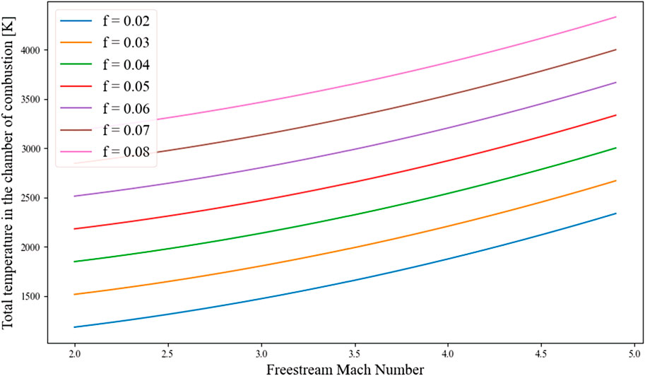
FIGURE 18. Total temperature in the chamber of combustion vs. Freestream Mach number.
5.4.3 Expansion
The results of the specific thrust and specific impulse are shown in Figure 19; Figure 20. As it can be seen, a smaller fuel-air ratio has a higher specific impulse at low Mach numbers. However, with the increase of the Mach number, the specific impulse for low fuel-air ratio decreases rapidly. This is explained by the fact that the air enters the chamber of combustion at already very high temperatures. Thus, not enough heat is supplied to the combustion gas, reducing the performances of the engine. In the same way, high fuel-air ratios provide higher temperatures in the chamber of combustion. So, the increase of the temperature along with the increase of the Mach number does not have a great impact on the performances of the engine and the specific impulse decreases slightly.
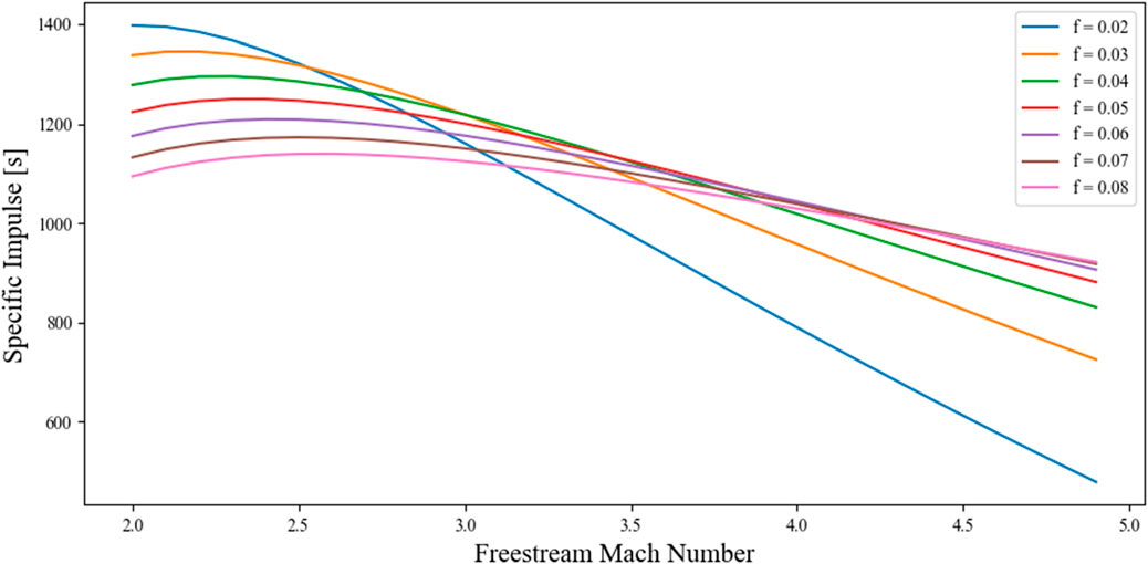
FIGURE 19. Specific impulse vs. Freestream Mach numbers.
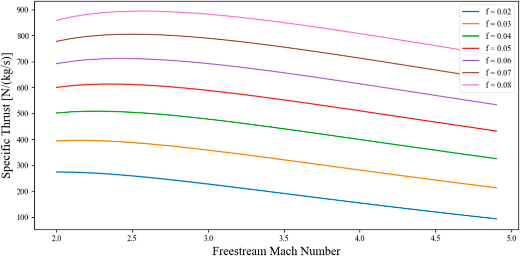
FIGURE 20. Specific Thrust vs. Freestream Mach numbers.
Figure 20 indicates that for the same thrust, a larger fuel-air ratio necessitates a smaller air flow rate, which in turn requires a smaller engine compared to a lower fuel-air ratio where a higher flow rate is needed to achieve the same thrust. This finding enables the selection of an optimal fuel-air ratio for a particular mission, thereby providing an initial estimate of the required engine size.
5.5 Trajectories for the RBCC and solid engines
The various characteristics calculated in the previous sections for the pure rocket mode gave the following results for a pressure in the chamber of combustion of 34.5 Bar.
• A temperature of combustion of 2984 K
• A mixture ratio, O/F, of 5.5
• A specific impulse of 260s
In Figure 21; Figure 22; Figure 23, the trajectories for the solid-propulsion missile and the combined cycle missile have been represented. For the HRBCC missile, the trajectory is depicted in orange when in rocket mode and in green when using the ramjet mode. In that way, from take-off until reaching Mach 2, the missile is in pure rocket mode. Once Mach 2 is reached, the inlet is opened, the missile enters the ramjet mode and relies totally on the oxygen in the atmosphere. Once all the propellant is consumed, the engine is turned-off and the missile continues its course until impact. For the same characteristics, it appears that the range reachable for the HRBCC engine is greater than the solid’s ones. If the HRBCC engine seems particularly advantageous for medium missiles, it reached a smaller altitude for the heavy missile, due to the difficulty for the hybrid rocket to accelerate efficiently the missile.

FIGURE 21. Trajectory of the RBCC and solid engine for the light missile.
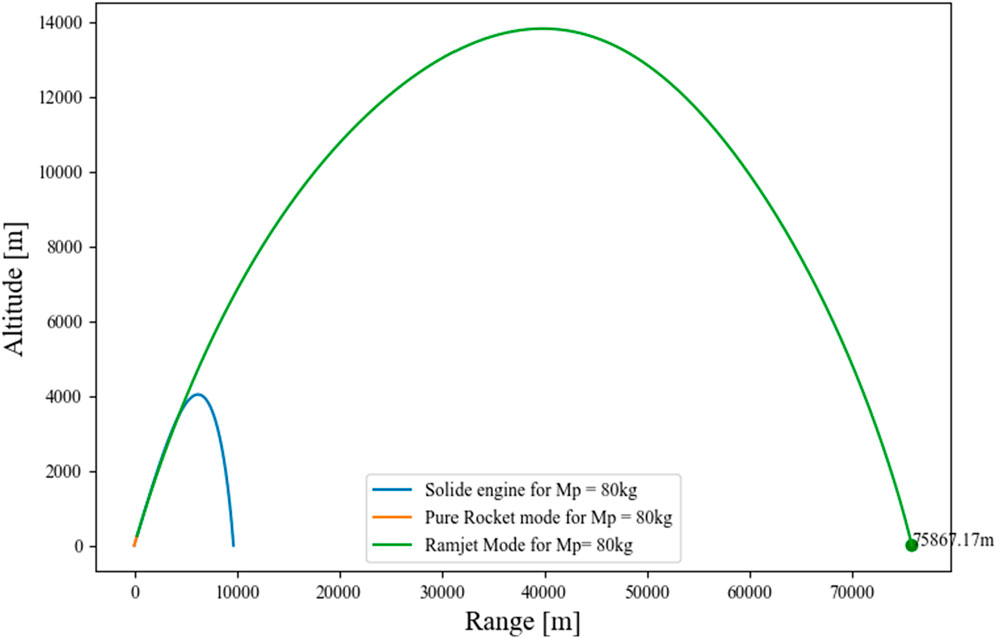
FIGURE 22. Trajectory of the RBCC and solid engine for the medium missile.
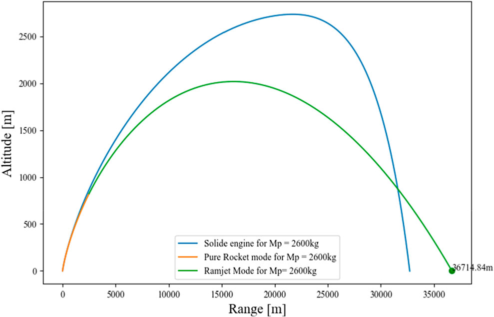
FIGURE 23. Trajectory of the RBCC and solid engine for the heavy missile.
The results of this study must be interpreted with caution. The analysis assumes that both missiles shared identical characteristics, which could not be the case in reality. As it was explained previously, the HRBCC engine is expected to be heavier than the solid one. In the same way, the configuration of the HyPrSpace’s engine would make the diameter of the missile larger, impacting its drag and, hence, its performance. In future studies, it would be more appropriate to compare missiles with specific missions and investigate how the resulting performance impacts the engine design. Furthermore, the trajectory model used is highly questionable as several hypotheses were made to simplify its complexity. The purpose was to provide a first approximation of the achievable performance by the HRBCC system with no intention of achieving precision. It was assumed that using the same model for both engines would suffice to gain insight into the differing behaviors of each engine during flight.
The variation of the propellant mass fraction during the flight has been analyzed for each missile propelled by an RBCC engine and presented in Table 2. The purpose was to determine the impact of the different modes (pure rocket and ramjet) on the propellant consumption. As expected, the pure rocket mode resulted in a high propellant consumption. For the light missile, the pure rocket mode consumed 93% of the total mass propellant, while it was 46% for the medium missile and 30% for the heavy one. These numbers depend on the ability of the rocket engine to efficiently accelerate the vehicle to the Mach of activation of the ramjet mode. In addition, by requiring an oxidizer tank and all the elements that go with it, the pure rocket mode increases the engine’s weight, impacting its performance. Therefore, the RBCC engine usually uses an ejector mode from take-off to supersonic speeds in order to reduce both the weight and propellant consumption. According to Amar and Reddy (2012), that mode is able to boost the performances of the rocket by 15%. However, it is one of the technical barriers that slows down the development of RBCC engines. The major difficulty of this mode comes from the relatively low thrust produced. Several studies have been carried out those past years to improve the overall understanding of the ejector mode and its possible enhancements (Lehman et al., 2000; Han et al., 2002; Heiser, 2010; Lin et al., 2017). In our future work, a study of the ejector-mode consumption and its performances will be investigated to define its suitability for military missions.
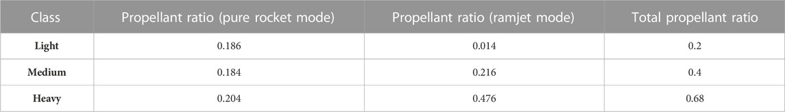
TABLE 2. Propellant ratio of the different modes according to the class weight.
6 Conclusion
This work provides a first estimation of the performances of a HRBCC engine. An overview of the several advantages and disadvantages of the hybrid propulsion over its competitors has been presented. Although liquid rocket engines have an efficient system and are more controllable, they are highly complex and subject to operational, safety and environmental problems. This is not the case for solid rocket motors as their fuel and oxidant are stored in a compact and solid way. However, the disadvantages of solid rocket motors include the lack of control and the risk of a pressure burst due to cracking of the grain. Hybrid propulsion is presented as an alternative due to its advantages of greater safety in the manufacture, storage and operation as well as being an inexpensive system in comparison with systems of liquid propulsion whilst retaining equivalent performances. Furthermore, hybrid propulsion addresses the challenges associated with variable thrust, serial firing, and storage of non-toxic propellants, which are not well-suited for solid rocket systems.
If several technologies barriers, like the slow regression rate or the shift in the mixture ratio OF, have slowed down the development of hybrid rocket engines, those barriers are now being removed thanks to innovative architectures like the one provided by HyPrSpace’s technology. Due to its unique configuration, the engine is able to reduce the various flaws, usually inherent to this type of propulsion, making this technology relevant and advantageous.
A simulation of the inlet’s profile according to the number of shockwaves generated has been developed. It was understood that the design of the inlet played a critical role in the determination of the engine’s performance. An analysis of the performance of the pure rocket and ramjet modes was investigated. The study showed the benefits of using a
Finally, the performance results were utilized to compute the trajectory of the HRBCC engine. In this model, only two modes were considered: the pure rocket mode and ramjet mode. The HRBCC’s trajectory was then compared to missiles with similar characteristics but propelled by solid engines. The results showed that the HRBCC outperformed the solid engine and could prove itself as a relevant technology for military applications. It was also highlighted that this work suffered from several limitations. For instance, the study assumed that the HRBCC engine possessed the same characteristics as the solid engines, which is challenging to achieve in reality. Additionally, the thermodynamic study of the ramjet mode was based on a perfect gas model, which does not accurately represent the complex phenomena that occur in this flight regime. Finally, the several assumptions taken for the trajectory model made the results found as unreliable in term of precision.
With the current context, the need to develop cost-effective and maneuverable vehicles capable to flight at high-speed has been well understood. Those requirements could be completed by using HRBCC engines that would be able to offer a competitive advantage over existing platforms. Hence, this research is intended as an initial assessment of the HRBCC engine’s capabilities, paving the way for further research on the subject.
Data availability statement
The original contributions presented in the study are included in the article/Supplementary Material, further inquiries can be directed to the corresponding authors.
Author contributions
All authors listed have made a substantial, direct, and intellectual contribution to the work and approved it for publication.
Funding
This research was funded by the French Defense Innovation Agency (AID) through a Ph.D. grant.
Conflict of interest
Authors LH and AM were employed by the company Hybrid Propulsion for Space.
The remaining author declares that the research was conducted in the absence of any commercial or financial relationships that could be construed as a potential conflict of interest.
Publisher’s note
All claims expressed in this article are solely those of the authors and do not necessarily represent those of their affiliated organizations, or those of the publisher, the editors and the reviewers. Any product that may be evaluated in this article, or claim that may be made by its manufacturer, is not guaranteed or endorsed by the publisher.
References
Aggarwal, R., Lakhara, K., Sharma, P. B., Darang, T., and Jain, N. (2015). SABRE engine: Single stage to orbit. Int. J. Innov. Res. Sci. Eng. Technol. 4, 10360–10366. doi:10.15680/IJIRSET.2015.0410107
Altman, D. (2003). Rocket motors, hybrid. Encycl. Phys. Sci. Technol., 303–321. doi:10.1016/b0-12-227410-5/00835-8
Amar, S., and Reddy, T. G. M. (2012). Air breathing rocket engines and sustainable launch systems. Appl. Mech. Mater 232, 310–315. doi:10.4028/www.scientific.net/amm.232.310
Chang, J., Zhang, J., Bao, W., and Yu, D. (2018). Research progress on strut-equipped supersonic combustors for scramjet application. Prog. Aerosp. Sci. 103, 1–30. doi:10.1016/j.paerosci.2018.10.002
Chiaverini, M. J., and Kuo, K. K. (2007). “Fundamentals of hybrid rocket combustion and propulsion,” in Fundamentals of hybrid rocket combustion and propulsion (American Institute of Aeronautics and Astronautics, Inc).
Daines, R., and Segal, C. (1998). Combined rocket and airbreathing propulsion systems for space-launch applications. J. Propuls. Power 14 (5), 605–612. doi:10.2514/2.5352
Davies, P., Hempsell, M., and Varvill, R. (2015). Progress on SKYLON and SABRE. Proc. Int. Astronaut. Congr. IAC 11 (2013), 8763–8771.
Dorrington, G. E., and Tec, E. S. A. F. (1990). Performance of air. Breathing single-stage-to-orbit vehicles list of main symbols list of main acronyms, 22. Noordwijk, The Netherlands: IAF, International Astronautical Congress.
Escher, W. J. D., Hyde, E. H., and Anderson, D. M. (1995). A user’s primer for comparative assessments of all-rocket and rocket-based combined-cycle propulsion systems for advanced earth-to-orbit space transport applications. Proceeding of the 31st Jt Propuls Conf Exhib. July 1995, San Diego,CA,U.S.A.
Foster, L. E., Saunders, J. D., Sanders, B. W., and Weir, L. J. (2012). Highlights from a Mach 4 experimental demonstration of Inlet Mode Transition for Turbine-Based combined cycle Hypersonic propulsion. 48th AIAA/ASME/SAE/ASEE Jt Propuls Conf Exhib. 1–15.
Han, S., Peddieson, J., and Gregory, D. (2002). Ejector primary flow molecular weight effects in an ejector-ram rocket engine. J. Propuls. Power 18 (3), 592–599. doi:10.2514/2.5973
Heiser, W., Pratt, D., Daley, D., and Mehta, U. (1994). “Hypersonic airbreathing propulsion [internet],” in Handbook of pediatric retinal OCT and the eye-brain connection (Washington, DC: American Institute of Aeronautics and Astronautics, Inc.), 285–287. doi:10.2514/4.470356
Heiser, W. H. (2010). Ejector thrust augmentation. J. Propuls. Power 26 (6), 1325–1330. doi:10.2514/1.50144
Heo, Y., Moon, K-H., and Sung, H-G. (2017). Investigation of Oswatitsch scheme for maximum total pressure recovery of hypersonic wedge-type intakes. J. Korean Soc. Aeronaut. Sp. Sci. 45 (12), 1031–1038. doi:10.5139/jksas.2017.45.12.1031
Krishnan, S., and George, P. (1998). Solid fuel ramjet combustor design. Prog. Aerosp. Sci. 34 (3–4), 219–256. doi:10.1016/s0376-0421(98)00005-0
Lehman, M., Pal, S., and Santoro, R. J. (2000). Experimental investigation of the RBCC rocket-ejector mode. Proceeding of the 35th Intersoc Energy Convers Eng Conf Exhib. July 2000, Las Vegas, NV,U.S.A. Las Vegas, U.S.A: AIAA.
Lin, B., Pan, H., Shi, L., and Ye, J. (2017). Effect of primary rocket jet on thermodynamic cycle of RBCC in ejector mode. Int. J. Turbo Jet-Engines 37, 1–10. doi:10.1515/tjj-2017-0013
McBride Sg, B. J. (1996). Computer program for calculation of complex chemical Equilibrium composition and applications II. Users manual and program description. Washington, DC: NASA Ref Publ. Available from: https://ntrs.nasa.gov/citations/19960044559.
Murthy, S., and Curran, E. (1991). High-speed flight propulsion systems. american institute of aeronautics and astronautics.
Musa, O., Xiong, C., Weixuan, L., and Wenhe, L. (2019). Combustion characteristics of a novel design of solid-fuel ramjet motor with swirl flow. Aerosp. Sci. Technol. 1, 750–765. doi:10.1016/j.ast.2019.07.003
Oswatitsch, K. (1980). Pressure recovery for missiles with reaction propulsion at high supersonic speeds (the efficiency of shock diffusers). Contrib Dev Gasdyn 1140, 290–323. doi:10.1007/978-3-322-91082-0_18
Palateerdham, S., Ingenito, A., and Ciprioti, S. (2020). “Experimental investigation of the paraffin thermomechanical properties and hybrid rocket engine performance for different fuel grain formulations,” in Thesis for: Masters in aerospace engineering advisor: Prof. Antonella ingenito, prof. Stefano vacchi chipro, prof. P. Hendrick.
Rui, X., Xin, H., Feixing, L., Xiaogang, M., Xing, Z., Jianxun, D., et al. (2021). A survey on the conceptual design of hypersonic aircraft powered by RBCC engine. Proc. Inst. Mech. Eng. Part C J. Mech. Eng. Sci. doi:10.1177/0954406220982011
Sutton, G. P., and Biblarz, O. (2017). Rocket propulsion elements. Ninth edit. Rocket propulsion elements: Ninth edition. Sutto, 20.1–20.104.
Tacca, H. E., and Lentini, D. (2010). Electric feed systems for liquid propellant rocket engines BioElectricTecnology view project. Available from: https://www.researchgate.net/publication/272086936.
Yang, Q., Chang, J., and Bao, W. (2014). Thermodynamic analysis on specific thrust of the hydrocarbon fueled scramjet. Energy 76, 552–558. doi:10.1016/j.energy.2014.08.052
Yang, Q., Shi, W., Chang, J., and Bao, W. (2023). Maximum thrust for the rocket-ejector mode of the hydrogen fueled rocket-based combined cycle engine. Int. J. Hydrog. Energy 40 (9), 3771–3776. doi:10.1016/j.ijhydene.2015.01.033
Zhang, D., Yang, S., Zhang, S., Qin, J., and Bao, W. (2023). Thermodynamic analysis on optimum performance of scramjet engine at high Mach numbers. Energy 90, 1046–1054. doi:10.1016/j.energy.2015.08.017
Zhang, T., Wang, Z., Huang, W., Ingham, D., Ma, L., and Porkashanian, M. (2020). An analysis tool of the rocket-based combined cycle engine and its application in the two-stage-to-orbit mission. Energy 193, 116709. doi:10.1016/j.energy.2019.116709
Zhangtian, T., Wangguo, Z., Huang, W., Chen, J., and Sunbo, M. (2019). The overall layout of rocket-based combined-cycle engines: A review. J. Zhejiang Univ. Sci. A 20 (3), 163–183. doi:10.1631/jzus.a1800684
Nomenclature
Greek
Subscript
Abbreviations
CEA Chemical Equilibrium Application
HRBCC Hybrid Rocket Based Combined Cycle
HTPB Hydro-Terminated Polybutadiene
RBCC Rocket Based Combined Cycle
SSTO Single Stage to Orbit
TSTO Two Stage to Orbit
Keywords: hybrid rocket, ramjet, RBCC, performances analysis, supersonic, inlet (intake)
Citation: Hillion L, Parisse J-D and Mangeot A (2023) Preliminary sizing and study of a hybrid rocket based combined cycle. Front. Space Technol. 4:1103981. doi: 10.3389/frspt.2023.1103981
Received: 02 December 2022; Accepted: 13 March 2023;
Published: 07 June 2023.
Edited by:
Jun Sun, Tsinghua University, ChinaReviewed by:
Feiteng Luo, Huazhong University of Science and Technology, ChinaNicholas Deak, National Renewable Energy Laboratory (DOE), United States
Copyright © 2023 Hillion, Parisse and Mangeot. This is an open-access article distributed under the terms of the Creative Commons Attribution License (CC BY). The use, distribution or reproduction in other forums is permitted, provided the original author(s) and the copyright owner(s) are credited and that the original publication in this journal is cited, in accordance with accepted academic practice. No use, distribution or reproduction is permitted which does not comply with these terms.
*Correspondence: Laurine Hillion, bGF1cmluZS5oaWxsaW9uQGh5cHItc3BhY2UuY29t; Jean-Denis Parisse, amVhbi1kZW5pcy5wYXJpc3NlQGVjb2xlLWFpci5mcg==