 Aishling Dignam1*
 Penelope J. Wozniakiewicz1,2*
 Mark J. Burchell1Luke S. Alesbrook1Adrian Tighe3Agnieszka Suliga3Johanna Wessing3Anton Kearsley2John Bridges4John Holt4Stuart Howie1Libby Peatman1Dennis Fitzpatrick5
- 1Department of Physics and Astronomy, Centre for Astrophysics and Planetary Science, University of Kent, Canterbury, United Kingdom
- 2Earth Science, ES Mineral and Planetary Sciences Division, Natural History Museum, London, United Kingdom
- 3European Space Research and Technology Centre, European Space Agency, Noordwijk, Netherlands
- 4School of Physics and Astronomy, University of Leicester, University Road, Leicester, United Kingdom
- 5Quorom Technologies Ltd., Lewes, United Kingdom
Observation of dust and debris in the near Earth environment is a field of great commercial and scientific interest, vital to maximising the operational and commercial life-cycle of satellites and reducing risk to increasing numbers of astronauts in Low Earth Orbit (LEO). To this end, monitoring and assessment of the flux of particles is of paramount importance to the space industry and wider socio-economic interests that depend upon data products/services from orbital infrastructure. We have designed a passive space dust detector to investigate the dust environment in LEO—the Orbital Dust Impact Experiment (ODIE). ODIE is designed for deployment in LEO for ∼1 year, whereupon it would be returned to Earth for analysis of impact features generated by dust particles. The design emphasises the ability to distinguish between the orbital debris (OD) relating to human space activity and the naturally occurring micrometeoroid (MM) population at millimetre to submillimetre scales. ODIE is comprised of multiple Kapton foils, which have shown great potential to effectively preserve details of the impacting particles’ size and chemistry, with residue chemistry being used to interpret an origin (OD vs. MM). LEO is a harsh environment—the highly erosive effects of atomic oxygen damage Kapton foil—requiring the use of a protective coating. Common coatings available for Kapton (e.g., Al, SiO2, etc.) are problematic for subsequent analysis and interpretation of OD vs. MM origin, being a common elemental component of MM or OD, or having X-ray emission peaks overlapping with those of elements used to distinguish MM from OD. We thus propose palladium coatings as an alternative for this application. Here we report on the performance of palladium as a protective coating for a Kapton-based passive dust detector when exposed to atomic oxygen and impact. When subjected to impact, we observe that thicker coatings suffer delamination such that a coating of <50 nm is recommended. Analysis of atomic oxygen exposed samples shows a thin 10 nm coating of palladium significantly reduces the mass loss of Kapton, while coatings of 25 nm and over perform as well as or better than other commonly used coatings.
1 Introduction
The dawn of the space age has seen the near Earth environment change significantly—the occasional meteoroid is now accompanied by thousands of satellites in orbit, plus the debris associated with them (Wozniakiewicz and Burchell, 2019 for a recent review). Humans are populating near Earth orbits with dead rockets, spent fuel and fragmentation debris, culminating in large numbers of orbital debris (OD) (Pardini, 2005). This is in addition to the natural dust population of micrometeoroids (MMs), primarily derived from comets, which leave behind a trail of dust on their orbits around the Solar System, and asteroids undergoing collisions (Trigo-Rodríguez and Blum, 2021). The composition of particles around the Earth is thus complex and ever-changing, creating the necessity for exploration and observation to evaluate the hazard it poses to spacecraft.
The total flux of all objects in LEO is important as all particles, regardless of origin, pose some threat. However, the individual flux within the OD and MM populations is crucial for assessing the level of hazard posed as each present a different potential threat. For example, the OD population typically travels at much lower velocities than that of the MM population but are generally made of more dense materials which can cause damage even at these lower velocities (Wozniakiewicz et al., 2019). Furthermore, understanding the OD flux informs us of the damage we are doing to the near Earth environment and thus the importance of minimising our debris to prevent the creation of serious problems for future spacecraft and astronauts alike.
On orbits higher than 900 km, especially around geosynchronous orbit (GEO), more care is taken to keep these orbits free of congestion; GEO is an indispensable resource to all space-faring nations and private parties which led to the Inter-Agency Space Debris Coordination Committee (IADC) in 1997 proposing and endorsing a policy of re-orbiting all dead satellites left in a torus around GEO to free up space and reduce the likelihood of collision (Anselmo and Pardini, 2008). This has been instrumental in maintaining low levels of OD in this orbit to date. However, inevitably over time the lack of dampening effects to speed up the orbital decay of OD (e.g., atmospheric drag) will see OD populations increase with expanded space activity in GEO (Anselmo and Pardini, 2008). To date, there have been no documented OD collisions or impacts further beyond GEO, although spacecraft on missions beyond Earth, e.g. to encounter other planets, such as Ulysses with an orbit out to Jupiter, have experienced impacts by MMs (Krueger et al., 2007).
1.1 Sources of dust: Orbital debris
Launching rockets creates a substantial amount of OD. Almost every rocket launched leaves a trail of solid rocket boosters and expended propellant behind. The upper stages of rockets account for 50% of the abandoned mass in LEO (Anselmo and Pardini, 2016). Venting the remaining propellant from leftover rocket bodies (a process referred to as passivation and performed since the 1980s) prevents these bodies from exploding and creating additional large amounts of debris, but itself generates debris from the liquid oxygen and hydrogen propellant (Rex, 1997).
The largest single contributor to the current larger particle OD population is without a doubt the collision and explosion of fully intact satellites. For example, in 2007, the Chinese satellite Fengyun-1C orbiting at an altitude of 863 km, was destroyed by a missile launched by China producing 3,037 (<4–5 cm) catalogued pieces of OD (Pardini and Anselmo, 2011). Modelling of these particles predicts that over 250 of these objects would survive in orbit after one century (Pardini and Anselmo, 2009). Despite best efforts to monitor OD and avoid collisions, in 2009 the accidental collision of Cosmos 2251 and Iridium 33 at an altitude of 789 km, generated a further 1,347 catalogued fragments greater than 4–5 cm in size as well as over 40,000 fragments larger than 1 cm that were inferred through radar observations (Pardini and Anselmo, 2011). Estimates suggest that the individual debris clouds from Cosmos 2251 and Iridium 33 will both decay from orbit faster than that from Fengyun-1C, but 10% of the Cosmos 2251 fragments will survive until 2037, with less than 1% of fragments from this collision left in orbit around 2090 (Pardini and Anselmo, 2011). The significant clouds of debris produced by the destruction of Fengyun-1C, and collision of Iridium 33 and Cosmos 2251 have thus drastically increased the amount of debris objects in the LEO environment for many years, increasing in the short term the probability of collision at altitudes of around 800 km by a factor of two (Pardini and Anselmo, 2011; Anz-Meador et al., 2018). More recently, the Russian satellite Cosmos 1408 was destroyed by a kinetic anti-satellite test in November 2021, creating a debris cloud of around 1,500 trackable pieces of debris (Williams, 2022).
1.2 Sources of dust: Micrometeoroids and meteoroids
In the vicinity of the Earth, meteoroids and micrometeoroids (MM) are thought to originate from a variety of sources, but particularly from comets and asteroids (Hoppe and Zinner, 2000). The primary mechanisms for dust production in the Solar System are through collision or emission. Colliding asteroids can produce large clouds of dust while comets sublimate volatiles when close to the Sun which ultimately liberates the dusty particles they held in place (Koschny et al., 2019). As the Earth travels through space it encounters these dust streams and thus is bombarded by sporadic meteoroids. Insights can be gained from these dust particles on the dynamical evolution of the Solar System and the threats they pose to spacecraft based on their trajectory, velocity and composition. The dust particles that reside in interplanetary space can also inform us about the evolution of their parent bodies and, in those cases where primitive bodies are sampled, the formation of the Solar System (Hoppe and Zinner, 2000).
Interstellar grains will also be present in the population of natural dust grains incident on the Earth. Some of these grains exhibit exotic compositions, having been formed and distributed through the galaxy by stars in the late stages of evolution (e.g., silicon carbide or corundum grains by moderate mass stars (1–8 solar masses) evolving through the asymptotic giant branch phase or silicon nitride grains by high mass stars (>8 solar masses) going supernova) (Hoppe and Zinner, 2000). Interstellar grains can inform us of the chemical makeup of the surrounding galactic environment and also of the nucleosynthesis processes inside the stars in which they were formed (Hoppe and Zinner, 2000). One example of a possible silicon carbide grain, which impacted upon a solar cell of the Hubble Space Telescope (HST) has been reported (Graham et al., 1999), and a collector capable of preserving recognisable materials from such grains would yield an important harvest of data.
1.3 Flux measurements
To date, various attempts have been made to determine the size distribution of particles in LEO. These can be divided into two main categories: those based on ground-based observations and those based on in situ measurements.
1.3.1 Ground-based observations
Remote sensing is a method by which we observe the OD population from Earth using radar and optical telescopes. The Goldstone Radar, a ground-based tracking station operated by NASA, is a powerful radar capable of detecting a conducting sphere 3 mm in diameter at an altitude of 1,000 km (Goldstein et al., 1998). The Haystack radar operated by Massachusetts Institute of Technology (MIT) Lincoln Lab, upgraded in 2010 to the Haystack Ultra-wideband Satellite Imaging Radar (HUSIR), can observe small debris objects of approximately 5 mm up to 1,000 km in altitude (Murray et al., 2019). The HUSIR radar utilises “beam-park” mode for observations of OD. In this mode the radar antenna points at a fixed elevation and azimuth and surveys particles which pass through the radar beam. By doing this the calculation of flux is simplified, although short observation times limit the ability to precisely measure the orbital parameters of the debris (Murray et al., 2019).
Optical telescopes are also used in the terrestrial monitoring of OD. Between 2001–2014 MODEST was NASA’s main optical detector for GEO debris and could detect objects greater than 30 cm in size (Lederer et al., 2017). The 1.3 m Eugene Stansbery Meter-Class Autonomous Telescope (ES-MCAT) on Ascension Island has been used by NASA since 2015 to observe and track OD with five-times more light-collecting power than its predecessor MODEST (Lederer et al., 2017). Its primary observing goal is to monitor and assess the OD environment with a focus on the GEO debris belt and the density and size range of the debris there (ARES Orbital Debris Program Office Optical Measurements, 2019). Its estimated detection limit is in the range 20–35 cm in GEO (Lederer et al., 2017).
1.3.2 In Situ measurements
To circumvent the detection limits in radar and optical observations, in situ measurements have been employed to sample a wide size range, especially the smaller particles that are not observable by remote techniques. This is particularly important as the smaller particle flux exceeds that for the ground-observed larger sizes, and impacts on space vehicles by grains in excess of even 100 µm can cause severe surface damage or penetration into the interior of a spacecraft unless it has protective shielding. Such detectors provide information for the particles in orbit at that specific altitude and can be either active or passive in design.
1.3.2.1 Active detectors
Active dust detectors are designed to respond to impact by particles, providing real time measurements to enable velocity, impact angle and estimated particle size to be determined. Some notable examples of active detectors used in the near Earth environment are the DEBris In orbit Evaluator (DEBIE), Geostationary ORbit Impact Detector (GORID) and Space Debris Sensor (SDS). Two DEBIEs were launched onboard the ESA PROject for On-Board Autonomy (PROBA) satellite in October 2001, into a polar low Earth orbit. DEBIE used multiple sensors to record each impact event; Impacting particles first passed through a thin aluminium foil mounted on an aluminium mesh, plasma generated by impact was then detected by sensors mounted in front and behind the foil-mesh (those behind only measuring plasma when penetration of the first foil occurred) while two piezoelectric crystals mounted with epoxy on the rear mesh measured impact momentum (Schwanethal et al., 2005). While in operation, DEBIE was sensitive to objects in the sub-millimetre range (Schwanethal et al., 2005). GORID, an impact ionisation detector, was launched onboard the Russian Express-2 telecommunications spacecraft in 1996 and was designed to measure the velocity, mass and approximate impact direction of the submicron to millimetre sized particle population in GEO (Drolshagen et al., 1999). NASA’s SDS was an experiment located on the outside of the International Space Station (ISS). The detector used the Debris Resistive/Acoustic Grids Orbital NASA-Navy Sensor (DRAGONS) to determine impacting particles’ size, speed, direction and density for particles in the 50–100 µm range using thin films coated with 75 µm wide resistive lines across three layers of foil, allowing for triangulation algorithms to determine the impactor speed, size and direction (Hamilton et al., 2017). This experiment was intended to operate for 3 years but unfortunately it experienced multiple anomalies leading to it becoming inoperable after only 26 days (Anz-Meador et al., 2019).
These methods may be effective in measuring particle flux in real-time but prior to the launch of SDS, most active detectors were small and thus were only likely to be impacted by (the higher flux) small particles during a relatively short exposure interval. Furthermore, these active detectors are not able to measure the chemistry of the incoming particle and, hence, are incapable of making the distinction between debris related to human space activity and the natural meteoroids and micrometeoroids (Wozniakiewicz et al., 2019). Time of flight mass spectrometer based dust detectors, such as those used onboard Cassini, are capable of measuring the chemistry of impacting particles, however, these typically have small collection/ionisation surfaces and are limited to analysing small particles (<1 µm) and thus are unlikely to get the necessary statistics for larger particles (Wozniakiewicz et al., 2021).
1.3.2.2 Passive detectors
Passive dust detectors are those requiring no power or other service inputs or outputs during deployment, and are typically surfaces that are exposed to impacts in the space environment. Upon return to Earth, these surfaces may be analysed in the laboratory for impact features (craters or penetration holes) and residues within them which may be used to interpret characteristics of the impacting particles (e.g., the size, shape and composition of the impacting particle). Passive collectors can be either dedicated or opportunistic.
1.3.2.3 Dedicated detectors
Dedicated passive detectors are those that have been designed specifically to collect or allow measurement of dust particles. Several dedicated dust detectors were deployed on the Long Duration Exposure Facility (LDEF)—a satellite carrying 57 experiments to survey the LEO debris environment, and which in the later 1980s spent 69 months in orbit at a mean altitude of 465 km. Post-flight, a total of 1,225 impact craters of 10–4,000 µm in diameter were recorded on the dedicated gold and aluminium measurement surfaces (Bernhard et al., 1993). In the early 1990s, the European Retrievable Carrier (EURECA) was exposed for nearly 11 months with a primary mission to study microgravity and was a valuable resource for impacts as it had a large exposed surface of 140 m2, collecting many particles (Drolshagen et al., 1996). The Timeband Capture Cell Experiment (TiCCE) was constructed of some thin aluminium foil arrays, capture cells and ultra low density aerogel (Brownlee et al., 1994; Burchell et al., 1999) to capture any impacting particles although the surrounding aluminium mesh also became valuable for determination of the particle flux (McDonnell et al., 1995). While extremely valuable to our understanding of the OD and MM populations, we note that all these dedicated collectors were retrieved over 25 years ago, thus are unlikely to represent the current population and composition of the LEO environment which has since had large contributions of OD from the various satellite disasters noted above.
1.3.2.4 Opportunistic returns
Opportunistic passive detectors are those surfaces with primary functions other than the capture of impacting dust particles (e.g., structural, thermal etc.) but nevertheless that collided with dust particles in LEO creating impact features that can subsequently be studied when returned to Earth. For example, impact features have been studied on returned heat-shield windows from Apollo 7–10 and 12–17 and subsequently from Skylab/Apollo windows (Cour-Palais, 1974), solar arrays and a radiator panel from the Hubble Space Telescope (HST) (Kearsley et al., 2005a), aluminium thermal control louvres and multi-layer insulation (MLI) blankets from the Solar Maximum Mission satellite (Warren et al., 1989) and MLI and Teflon radiators from the Space Flyer Unit (Yano et al., 1997). Non-dedicated surfaces on missions carrying dedicated passive detectors have also proven extremely valuable to studies of flux, since they often comprise larger areas pointing in many different directions, for example, solar arrays and MLI on EURECA and tray clamps holding experiments in place on LDEF (Bernhard et al., 1993; Herbert and McDonnell, 1997). Since these are not purpose-built for the study of impact features, there are often difficulties in their analysis (e.g., distinguishing the chemistry of impactor and that of spacecraft surface, difficulty determining impactor size from impact feature size which leads to uncertainties or poor statistics in the flux values determined (Kearsley et al., 2005b)).
From previous studies of the LEO environment with active and passive detectors as well as opportunistic returns, a gap of in situ measurement data for the individual OD and MM populations has been identified by Wozniakiewicz et al. (2019). Data for particles smaller than 200 µm have been obtained through analyses of returned surfaces, as listed above, and in some cases OD and MM origins have been established allowing the individual fluxes to be determined. Yet, limited data from in situ measurements exists for particles above 200 μm, thus, although particles larger than 2 mm can be observed using ground-based observations, there is a lack of data for particle sizes between 200 μm and 2 mm (Wozniakiewicz et al., 2019). Furthermore, most of the returned surfaces (dedicated and non-dedicated) are outdated, being retrieved over 25 years ago—several major debris generating events have since occurred (e.g., Fengyun-1C detonation) and there has been a substantial increase in space traffic. Consequently, to determine the current flux of these populations, and fill the identified data gap, new measurements of the LEO environment by new detectors are required.
1.4 Orbital dust impact experiment (ODIE)
Based on the previous studies of the LEO environment, we have chosen a passive detector design as this is optimal for discerning the particle composition over a range of sizes thus allowing for the data gap to be addressed. The Orbital Dust Impact Experiment (ODIE) is similar in concept to the multilayer polymer experiment (MULPEX) (Kearsley et al., 2005b) being composed of multiple Kapton foils with the overall structure comprised of individual cells to allow the design to cater to any space available (Wozniakiewicz et al., 2019). Its design is based on a Whipple shield such that the incoming particle gets disrupted as it impacts with the front foil, similar to the capability of multilayer insulation to capture orbiting particles. Using the thinnest sheet of Kapton as the first space-exposed layer (with thicker sheets in subsequent layers) gives the front foil the ability to preserve details of the shape and size of the impactor based on the dimensions of the impact feature (Kearsley et al., 2005b). As the particle travels through the foils, it deposits residue on each impact feature it creates. Upon retrieval and return to Earth of the detector, the residues present on the impact features can be analysed using the wide range of analytical techniques available on ground, most notably scanning electron microscopy (SEM). However, although the Kapton foil is an excellent capture medium, it is vulnerable to erosion by the atomic oxygen present in LEO and therefore needs a protective coating.
1.5 Atomic oxygen
Atomic oxygen in LEO collides with spacecraft at relative velocities of ∼7.4 km s−1 with fluxes in the range of 1013–1015 atoms cm−2 s−1, potentially causing severe erosion of external materials on the craft, thus motivating studies of the extent of damage this can cause (e.g., Cooper et al., 2008). Understanding the deleterious effects of the space environment on spacecraft materials was the main goal of the Long Duration Exposure Facility (LDEF) which, as stated above, was deployed for 69 months in a circular orbit (typical altitude 465 km) with inclination 28.5°. The atomic oxygen fluence in this orbit was measured post-flight, with the ram-facing fluence determined to be 9.02 × 10²¹ atoms cm−2 s−1 and wake-facing fluence found to be ∼103 atoms cm−2 s−1 (Banks 1990). LDEF and Space Shuttle flight data show that the atomic oxygen erosion of Kapton is linearly predictable with atomic oxygen fluence (Silverman, 1995). The erosion of polymeric materials can be prevented through the use of coatings, with even extremely thin coatings on the orders of nanometres providing adequate protection from atomic oxygen degradation (Silverman, 1995). Coatings applied via sputter-deposition on polymers, such as Kapton, were found to be effective at preventing mass loss in LEO (experiment A0134) (Silverman, 1995).
Using the thinnest layer of coating possible is optimal as thick coatings are more likely to produce cracks, creating a point of entry for the atomic oxygen (Cooper et al., 2008). Only the space exposed side of the polymer is coated to prevent atomic oxygen undercutting; A process by which the atomic oxygen enters the polymer through a crack, bouncing between the two layers of coatings and causing more damage than having an exposed back surface (Cooper et al., 2008). Particulate debris on the surface of the polymer at the time of coating or scratches on the surface of the polymer may also result in defects in the coating, presenting an opening for the atomic oxygen to attack the protected polymer beneath and increase the size of the original defect. Therefore, in the preparation of the polymer a clean environment needs to be maintained to reduce the likelihood of defects and ensure the deposition of a smooth coating (de Groh and Banks, 1994).
A common coating utilised for Kapton foil is aluminium, which has been found to be effective at protecting against atomic oxygen (Cooper et al., 2008). Gold, a highly utilised coating, and platinum also both provide good protection being unreactive to atomic oxygen (Silverman, 1995). Silicones are useful coatings that have the ability to form a SiOx glass-like film which can protect itself from atomic oxygen attack (Silverman, 1995). Germanium coated black Kapton is used as a thermal control on the sunshield of satellite antennae as it is transparent in radio frequencies, whilst also protecting the underlying Kapton from atomic oxygen (Prajwal et al., 2018). Although widely utilised, germanium coatings are particularly vulnerable to oxygen degradation during storage on the ground, with a typical shelf life of only ∼6 months (Esther et al., 2015).
While these coatings have been shown to provide effective protection against atomic oxygen, for the purposes of our detector they each have significant drawbacks. Firstly, the detector would be returned to Earth for extensive analysis and thus must remain stable in an oxygen-rich environment, hence a germanium coating is unsuitable. On return to Earth the samples would be analysed by SEM, utilising energy dispersive X-ray analysis to investigate chemistry of residues and distinguish between those of OD and MM origin, as SEM-EDX is probably the most time and cost effective large scale analytical method for surveying very large numbers of small impact features for the initial screening phase of the post-flight investigation. Other techniques (e.g., micro-XRF, synchrotron XRF, Auger, PIXE, ToFSIMS) could potentially yield more precise data on the particle composition as part of a more in-depth investigation. The other common coatings of aluminium, gold, platinum and silicones all have the disadvantage of being a common elemental component of MM (silicon) or OD (aluminium), or of having X-ray emission peaks that overlap with peaks for elements that can be used to distinguish an MM from OD (gold and platinum overlap with peaks for sulphur which is a common diagnostic element present in MMs but not OD) (Kearsley et al., 2005b). Thus, the detector requires an alternative coating to provide the necessary protection from atomic oxygen damage. Palladium has been chosen as its X-ray peak does not overlap with those of sulphur (or any diagnostic elements) as shown by Kearsley et al. (2005b).
In this paper we therefore investigate the suitability of palladium as a protective coating for Kapton. The effectiveness of the coating is assessed on the basis of its reaction to hypervelocity impact and exposure to atomic oxygen, two key conditions of exposure in LEO.
2 Experimental methodology
In order to evaluate the effectiveness of palladium as a protective coating and determine the optimum coating thickness two investigations were conducted. The first focused on studying the impact features formed on the palladium-coated Kapton during hypervelocity impact experiments and the second sought to study the erosion experienced by palladium-coated Kapton when exposed to atomic oxygen.
2.1 Sample preparation
All foils used in the work presented here were 25 µm thick Dupont Kapton HN (referred to as Kapton herein). Prior to their exposure to impact and/or atomic oxygen, the foils required cutting to size and coating with palladium. For coating, all Kapton foils were first cut to measure 3 × 4 cm. Copper tape was placed around the edges of the foils to create a firm edge that prevented the foil from rolling up and to aid in their handling. They were then mounted onto a photographic slide frame using fine rubber bands at the corners, which acted to keep the foils flat during coating and prevent their movement from the coating platform when the coater was put under vacuum (Figure 1A). Q150T ES and Q150V ES Plus sputter coaters by Quorum Technologies were then used to apply palladium coatings ranging from 10 to 100 nm thick via sputter deposition. A film thickness monitor pre-installed on the coater measures the coating thickness using a crystal inside the coating chamber which measures the quantity of palladium deposited. After the coating was deposited, the coatings were examined using a Hitachi S-3400 SEM to search for defects and assess the coating quality (Figure 1B).
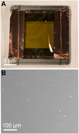
FIGURE 1. (A) The Kapton foil with copper tape mounted on a photographic slide with rubber bands prepared for coating. (B) An SE image of the coating surface showing the condition of a 10 nm coating of palladium.
2.2 Hypervelocity impact experiments
The hypervelocity impact experiments were conducted using the two-stage Light Gas Gun facility at the University of Kent, Canterbury, United Kingdom. Foils coated with 10 nm, 20 nm, 30 nm, 40 nm, 50 nm and 100 nm of palladium were prepared and, together with an uncoated foil, mounted within the photographic slide frames (used previously as a base during coating and now as a target holder, Figure 2) and subjected to impact by well-characterised projectiles at approximately 5 km s−1.
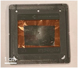
FIGURE 2. A foil post-impact with the buckshot mix at a speed of approximately 5 km s−1.
A projectile mix was produced comprising several monodisperse components that are analogues for MMs or OD: 1 ± 0.005 mm basalt (MM), 108 ± 4 µm soda lime glass (MM), 50 ± 1 µm molybdenum (OD) and 7 ± 0.5 µm silica (MM). Each shot contained a single 1 mm basalt sphere along with a mixture of the all of the other powders. This mix was placed in the sabot and shot as a buckshot. The monodisperse nature and substantial gap in sizes was chosen to ensure impact features could be ascribed to an individual projectile type based solely on the impact feature size. Details of the powder shot and velocity measurement techniques employed here are described in Burchell et al. (1999). For each shot, the target was mounted in the blast tank of the gun to minimise contamination during the shot and maximise the number of impacts generated on the target foil. As such, the main time of flight system was unable to be used and thus, speed measurements were taken using the secondary muzzle laser and exit aperture PVDF sensor system. The changes in the target mounting locations also necessitated a corresponding change in the separation of the two detectors from 0.8475 m (as described in Burchell et al. (1999)) to 0.6595 m to enable the mounting of the target behind the exit aperture. Therefore the errors in speeds are slightly above those stated at ±5%. The shots occurred in a vacuum of typically 0.5 mbar.
The projectile mix and impacted foils were both imaged using a Hitachi S3400-N scanning electron microscope (SEM) in the School of Physical Sciences at the University of Kent. A combination of secondary and back scattered electron imaging was used. Images were obtained to illustrate the response of the coating to impact (e.g., cracking, delaminating) and determine how this varied for different coating thicknesses.
2.3 Atomic oxygen exposure
Samples were sent to ESA’s Low Earth Orbit (Atomic) Oxygen space environment simulation facility (LEOX) at the European Space Research and Technology Centre (ESTEC). Foils coated with 10 nm, 25 nm, 50 nm, 75 nm and 100 nm palladium were prepared and their central area cut out to produce square samples measuring 2 × 2 cm in accordance with sample specifications for atomic oxygen testing at the LEOX facility. An additional 10 nm coated foil that was impacted (under the same conditions as described earlier) and an uncoated sample were also cut to determine how much impact features enhance the erosion of Kapton under atomic oxygen and to act as a control sample respectively. Details of the facility and sample setup can be found in Tighe (2010). The samples were imaged optically and weighed before and after exposure. Measurements of mass were accurate to ±10 mg. An average atomic oxygen fluence of 2 × 10²¹ atoms/cm2 over the sample surfaces was targeted. The actual atomic oxygen fluence experienced by samples at different locations on the sample plate was calculated by knowing the atomic oxygen flux distribution from the pre-test, in which Kapton occupies all test slots. During the actual exposure, the flux distribution is measured only at certain locations and the flux map is recreated for all the slots.
The foil samples returned after atomic oxygen exposure were first imaged optically and then by SEM. During exposure to atomic oxygen, the foils were held within the sample plate by a frame with a circular exposure area which thus covered the corners of each sample. When imaging in SEM, the foils were mounted for analysis with the boundary between the exposed and covered sections visible to aid identification of atomic oxygen induced damage. Images were obtained to illustrate the nature of any damage to the coating. In addition, impact features >80 µm in size (and assumed to result from the same projectile in the projectile mix used) were measured on both of the 10 nm coated and shot foils that were and were not exposed to atomic oxygen to determine whether the dimensions of impact features are preserved after atomic oxygen exposure. These features were measured in two ways, first the diameter of the penetration hole was measured and second the diameter of the feature from rim-torim was measured (Figure 3). The raised rim which surrounds the hole is folded back foil and the rim-to-rim diameter is taken from the peak height of the rim.
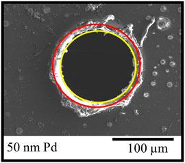
FIGURE 3. Example diameter measurement locations on an impact from a hypervelocity impact experiment. The red outer ring is the approximate location of the rim, and the yellow inner ring is the hole in the foil.
3 Results
3.1 Performance of palladium coating under hypervelocity impact
The projectile mix was successfully fired at the uncoated and palladium coated foils—details of these shots are provided in Table 1. Similar impact features—a mixture of larger circular penetration holes over ∼ 100 µm in size with thin rims and a range of smaller impact craters—are observed on foils coated with different thicknesses of palladium. The coating itself, however, exhibited cracking, delamination and loss of the coating around the impact features (Figures 4, 5). Loss of the coating is far from ideal for the purpose of ODIE as the palladium must remain attached to the Kapton foil in order to form a protective coating and preserve the original hole dimensions.
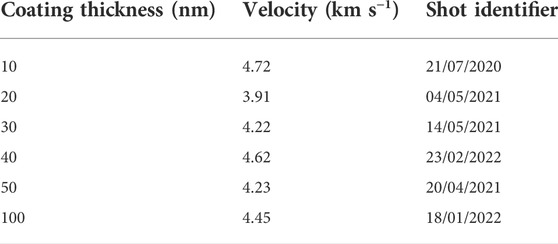
TABLE 1. Details of shots performed in this study. Velocities have error values of ±5%. Shot identifiers are used within the light gas gun facility to link samples to experimental records.
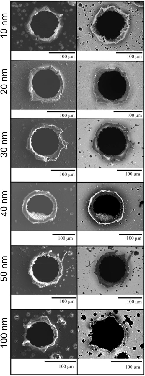
FIGURE 4. Comparison of the impact holes generated by 103 µm soda lime glass spheres in Kapton coated in different thicknesses of palladium. The left column are secondary electron images and the right column are backscattered electron images. The palladium coating appears bright in backscatter images enabling rapid location of impact features and coating damage (e.g., delamination).
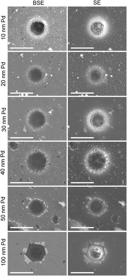
FIGURE 5. Damage to different thickness palladium coatings observed around small impact features on Kapton foils. Secondary electron and backscattered images are provided for each feature. The coating around small impact features on the 10 nm, 20 and 30 nm Pd coated foils appears cracked, with damage progressing to delamination and peeling back of the coating in the 40 nm, 50 and 100 nm palladium coated foils. Scale bars on each image represent 10 µm.
It can be seen in Figure 5 that there is concentric cracking around the holes and also cracking expanding outwards radially. There are numerous radial fractures around the holes in the thinner coatings, and the coating peels backwards and upwards without concentric fractures forming at the base of each petal, leaving the peeled back coating attached at its base. However, in the thicker coatings, there are fewer radial fractures, and concentric fractures form at the base of some raised petals, causing them to detach.
The thicker coating thus seems to form larger segments when peeling from the surface around the impact features. The thinner coatings, especially the 10 nm coating in Figure 5, perform better in this regard, as the thinner coating seems to radially fracture more easily as it is raised around the impact site and does not break away in large chunks from around the impact feature. Therefore, thinner coatings are best for the overall coverage of the detector surface as they do not display additional peeling/detaching effects as a result of the impact.
3.2 Atomic oxygen exposure
Optical images of the ATOX exposed foils are presented in Figure 6. An immediate observation was that, as expected, the uncoated Kapton had been completely eroded during its exposure to atomic oxygen leaving just the four corners that were protected by the overlying sample tray frame (Figure 6B). For all remaining coated foils, a clear difference in the optical properties was visible at the boundary of the circular exposed area—the exposed regions appear to have darkened.
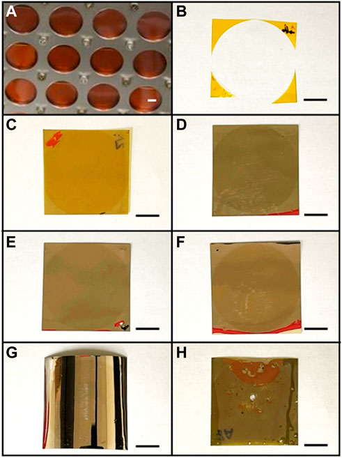
FIGURE 6. Post-exposure samples of 25 µm think Kapton. (A): Section of the ATOX facility sample holder showing a circular region of each sample for exposure to atomic oxygen. (B): Uncoated 25 µm Kapton. (C): 10 nm palladium coated Kapton. (D): 25 nm palladium coated Kapton. (E): 50 nm palladium coated Kapton. (F): 75 nm palladium coated Kapton. (G): 100 nm palladium coated Kapton. (H): Impacted 10 nm palladium coated Kapton. Scalebars in each image represent 0.5 mm.
SEM images acquired across this boundary show a line of increased brightness at the boundary between exposed and non-exposed material for all of the coated foils (Figure 7 shows this feature for both the 10 and 100 nm coated foils). Such changes in brightness are not, however, observed in BSE images, and indeed EDX spectra obtained over exposed and covered regions of the foils exhibit no clear differences, suggesting the chemistry remains the same (i.e. no measurable oxidation of the exposed regions).

FIGURE 7. SE images of the boundaries between the exposed and covered areas of 10 nm (A) and 100 nm (B) palladium coatings. In each case the exposed area is the upper portion of the image, and the boundary is indicated with an arrow.
This is consistent with findings from Silverman (1995) where, other than a dulling of the coating, no discernible difference in optical properties were observed across the exposed-unexposed boundary of various coated Kapton foils exposed to atomic oxygen in LEO.
On closer inspection with the SEM, evidence of erosion of the Kapton surface was found on all foils to varying degrees. The 10 nm coated foil had many small holes across the surface as well as some larger features as can be seen in Figure 8A that show large areas of the foil being eroded. The other thicknesses of coating did not show damage to the same extent with a complete lack of features akin to those in Figures 8A,B. While all presented with small holes, there were fewer on the thicker coatings of palladium with notably less larger holes present. We note here that the holes created by the atomic oxygen (the result of exploitation of defects in the coating) are markedly different from those features greater than ∼50 µm in diameter formed in the hypervelocity impacts: these larger impact features exhibit rims that are not present on atomic oxygen erosion holes of similar sizes. For smaller features, (less than ∼5 µm) it was not possible to discern an origin as no clear evidence of rims could be found after atomic oxygen exposure. The threshold size at which atomic oxygen erosion holes and impact features can be distinguished could not be determined here due to a lack of features of intermediate size created during impact of our projectile mix with discrete impactor sizes but should be considered in future work.
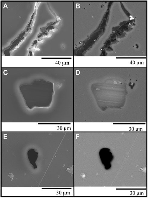
FIGURE 8. Atomic oxygen damage on the 10 nm (A–D) and 100 nm (E,F) coated foils. (A,B): Long damage feature on the 10 nm coated foil in SE (left) and BSE (right). Long filaments of Kapton can be seen to be stretching across the gap formed. (C,D): Large hole feature on the 10 nm coated foil. (E,F): Small hole on the 100 nm coated foil.
The mass loss per unit area observed for the different foils is plotted in Figure 9. This mass loss is dominated by Kapton erosion by atomic oxygen in all cases. These data have been normalised to represent mass loss due to exposure to the equivalent of 1 year’s fluence at an orbit of 400 km (2.087 × 10²¹ atoms/cm2, the average value determined from solar maximum and minimum data presented in Banks et al., 2004) and have been corrected to remove the mass incorporated in the unexposed corners. The uncoated 25 µm Kapton foil is not plotted since the exposed region was completely eroded and the impacted sample is also not plotted as its mass loss was off the scale of the plot. By contrast, all of the coated foils survived such that it is clear the palladium coating has at least been successful in providing protection to the underlying Kapton from atomic oxygen. Of the coated foils, the thinnest coating (10 nm) was the least effective in preventing mass loss as might be expected. It does not, however, appear to follow that a greater level of protection is provided as the coating thickness is increased: based on the observed mass loss, the best protection was provided by the 75 nm coating, followed by the 25 nm coating, the 100 nm coating and finally the 50 nm coating. Given that atomic oxygen exploits imperfections in coating surfaces to erode the protected layer underneath, it is possible that variation in the initial number of imperfections from foil to foil may have contributed to this and resulted in thinner coatings (with perhaps fewer imperfections) apparently providing better protection than thicker coatings.
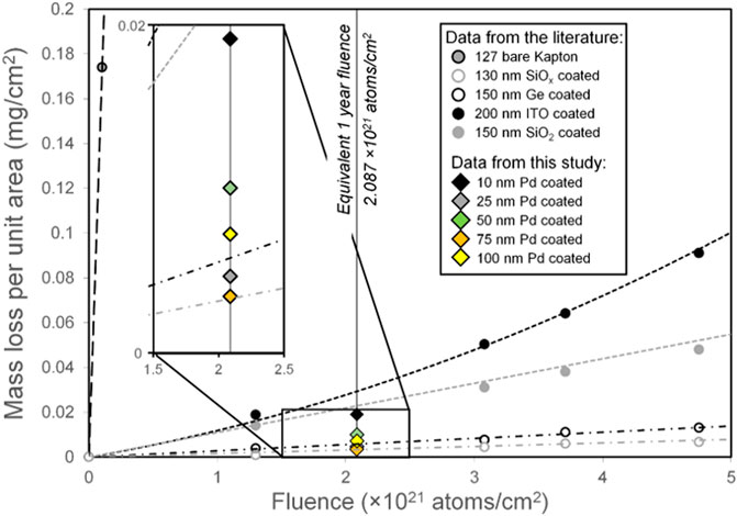
FIGURE 9. The mass loss of the different samples and the atomic oxygen fluence imparted on the samples compared to other common coatings (Silverman 1995).
For comparison, data for uncoated and a variety of coated Kapton foils from the literature have also been plotted in Figure 9; 25.4 µm Kapton coated with 130 nm SiOx (1.9 < x < 2.0), 50.8 µm Kapton coated with 150 nm thick SiO2, 50.8 µm Kapton coated with 150 nm thick Germanium, 50.8 µm Kapton coated with 200 nm indium tin oxide (ITO) as well as uncoated 12.7 µm Kapton. The palladium coatings of this study all performed better than ITO and SiO2 coatings, with the 25 and 75 nm coatings also outperforming germanium. Only the SiOx coating was better than every palladium coating.
Although intact after exposure, the impacted foil suffered a mass loss equivalent to approximately 2.7 mg cm−2 for 1 year’s atomic oxygen fluence from the exposed region, consistent with the SEM observations noted earlier. The impacted foil therefore lost twenty times as much mass as its unimpacted counterpart. Consequently, this plots well beyond the region displayed in Figure 9.
Comparing images of the 10 nm palladium coated impacted foils prior to and after exposure to atomic oxygen, there are clear indications of mass loss, with many of the impact holes located close together prior to atomic oxygen suffering erosion of the remaining Kapton between them to become single impact features (Figure 10). The rims of the impacts are completely intact and thus remain measurable—possibly as a result of the Kapton and palladium being thicker at these parts hence preventing erosion of the material as quickly.
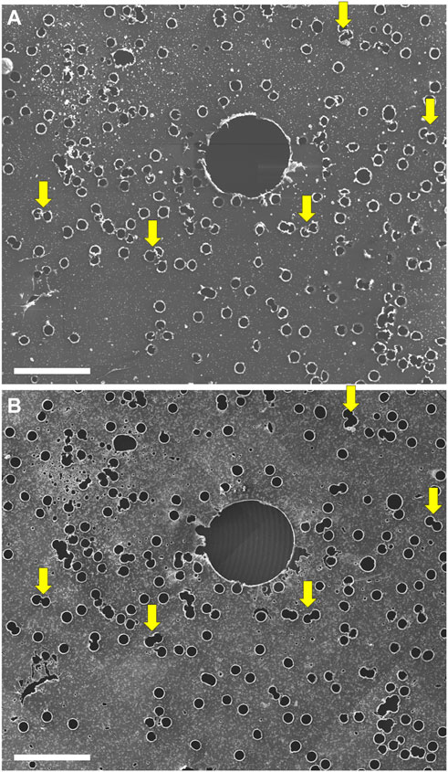
FIGURE 10. SEM images of the impacted 10 nm palladium coated foil. (A): prior to atomic oxygen, and (B): after exposure to atomic oxygen. In A, the large hole was from impact by a single 1 mm size projectile, and the multiple small holes were from the accompanying smaller particles, predominately 103 µm soda lime glass, present in the buckshot mix. Yellow arrows mark examples of closely located impact features, where the Kapton remaining in between has been eroded away by atomic oxygen exposure leaving a single hole. The scale bars represent 1 mm.
Further, when comparing the atomic oxygen exposed, impacted 10 nm palladium coated foil to the 10 nm palladium coated foil that was exposed to atomic oxygen only, the degree of atomic oxygen damage is clearly much greater on the foil that was impacted, with abundant erosion pits visible across the surface (Figure 11). The impacted 10 nm coated foil shows complete erosion of Kapton beneath the palladium coating in areas and pitting across the exposed surface, facilitated by the large number of holes in the coating produced by impact, allowing entry of atomic oxygen. The undercutting effects on the surface are comparable to those observed by de Groh and Banks (1994) where there are pits and small channels created in the surface (de Groh and Banks, 1994). We note that the number of impact features produced on the foil in our laboratory by the light gas gun is far greater per unit area than would be anticipated during 1 year of exposure to atomic oxygen in Earth orbit and thus, this level of damage and mass loss should be regarded as an extreme upper limit.
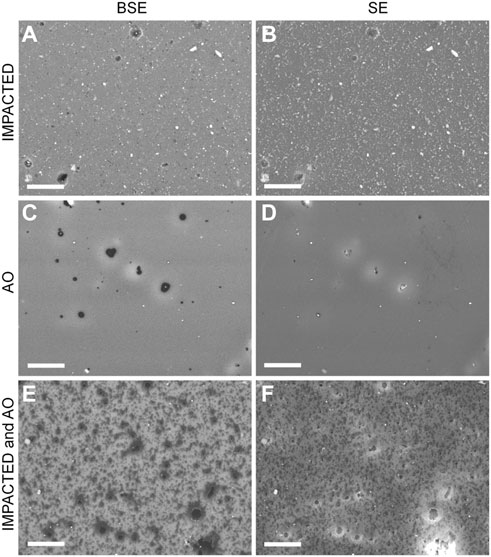
FIGURE 11. Backscattered electron (BSE) and secondary electron (SE) SEM images comparing the surfaces of (A,B): The impacted 10 nm palladium coated foil, (C,D): The 10 nm palladium coated foil exposed to atomic oxygen and (E,F): The impacted 10 nm palladium coated foil exposed to atomic oxygen. Scalebars represent 10 µm in each image.
Measurements of the hole diameters for impact features >80 µm in diameter and <150 µm (not including the 1 mm basalt impact) on the impacted 10 nm palladium coated foils that were and were not exposed to atomic oxygen revealed an average size of the central hole measurement of 130 ± 5 μm and 110 ± 19 µm in diameter respectively. Exposure to atomic oxygen therefore appears to result in a ∼18% increase in impact feature diameter due to erosion of the underlying Kapton. Further work is needed to determine whether this size modification varies with the original impact feature dimensions. However, rim-to-rim measurements for the non-exposed features are 125 ± 12 μm and 142 ± 6 µm for the exposed features. These impact features differ by ∼13% and thus may provide a better means for quantifying relationships between impactor and impact feature dimensions. This smaller difference implies that the diameter measurements to be taken from these impact features should be taken on the rim of the impact features as the size information is preserved more than that of the central hole.
4 Discussion
In summary, we have shown that palladium coatings can survive hypervelocity impact, although increasing the coating thickness eventually leads to increased cracking at approximately 30–50 nm thickness and ultimately delamination of the coating upon impact. This would suggest the coating needs to remain below 50 nm to avoid excess loss of protective coating upon impact (which would lead to increased erosion by atomic oxygen from those newly exposed areas). Future work could investigate the adhesion of the palladium to the Kapton and how it could potentially be improved by pre-treating the surface of the Kapton.
We have demonstrated the effectiveness of palladium as a protective coating for Kapton against atomic oxygen, with all coating thicknesses providing significant protection compared with uncoated Kapton. Studying the atomic oxygen exposed coated samples has shown the best protection (resulting in least mass lost) was provided by a palladium coating thickness of 75 nm, with the 10 nm coating being the least effective at protecting against atomic oxygen. However, the yearly mass loss calculated for the different thickness coatings did not decrease systematically with increased coating thickness as might be expected. This suggests other factors, such as the number of coating imperfections leading to undercutting by atomic oxygen, may have contributed to the mass loss experienced. This highlights the importance of minimising coating imperfections by, for example, ensuring clean working areas during foil preparation prior to coating to avoid the introduction of debris on the surface which can ultimately lead to gaps in the coating. Nevertheless, the protection provided by palladium is comparable to, or better than, that offered by other coatings available.
After atomic oxygen exposure, mass loss data suggest the impacted 10 nm palladium coated foil would suffer twenty times as much mass loss over a year when compared to its unimpacted counterpart. We do not expect to see such densely packed impacts on space exposed samples even after a year, thus would not anticipate this associated level of mass loss over the whole foil. Comparison of impact features on raw impacted samples and those exposed to atomic oxygen do, however, suggest impact feature dimensions may be increased as a result of erosion by atomic oxygen, therefore further work is required to define the size relationships between impacting particles and their resulting impact features on atomic oxygen exposed Kapton. This, combined with atomic oxygen exposure tests involving impacted foils with up to 75 nm palladium coatings, would enable determination of the optimum coating requirements to minimise mass loss and thus error in impacting particle size calculations. Based on the results here, however, we recommend a coating of at least 25 nm to protect Kapton against atomic oxygen, but no greater than 50 nm to prevent excessive damage and loss of that coating (and associated atomic oxygen damage) through delamination and cracking upon impact.
Data availability statement
The raw data supporting the conclusion of this article will be made available by the authors, without undue reservation.
Author contributions
AD performed the sample preparation, impact experiments, SEM analysis and data analysis. PJW aided in the experimental design, sample preparation, SEM analysis and data analysis. MJB aided in experimental design and data analysis. LSA operated the light gas gun for the experiments. AT, AS, and JW performed the atomic oxygen testing of the samples. AK, JB, and JH aided in the experimental design. SH and LP aided in the SEM analysis. DF aided in coaters for sample preparation.
Funding
University of Kent Vice Chancellor Scholarship funded AD’s PhD research. STFC grants support operation of the light gas gun facility ST/S000348/1.
Acknowledgments
AD would like to thank a University of Kent VC Scholarship for funding her PhD. PW and MB would like to thank STFC grant ST/S000348/1 for support of the light gas gun facility. The ATOX tests were realised within ESA's open lab campaign in ESTEC's Materials and Components Laboratory (ESA-TECQE-AO-013375).
Conflict of interest
DF was employed by the company Quorom Technologies Ltd.
The authors declare that the research was conducted in the absence of any commercial or financial relationships that could be construed as a potential conflict of interest.
Publisher’s note
All claims expressed in this article are solely those of the authors and do not necessarily represent those of their affiliated organizations, or those of the publisher, the editors and the reviewers. Any product that may be evaluated in this article, or claim that may be made by its manufacturer, is not guaranteed or endorsed by the publisher.
References
Anselmo, L., and Pardini, C. (2016). Ranking upper stages in low Earth orbit for active removal. Acta Astronaut. 122, 19–27. doi:10.1016/j.actaastro.2016.01.019
Anselmo, L., and Pardini, C. (2008). Space debris mitigation in geosynchronous orbit. Adv. Space Res. 41, 1091–1099. doi:10.1016/j.asr.2006.12.018
Anz-Meador, P. D., Opiela, J. N., and Shoots, D. (2018). History of on-orbit satellite fragmentations. Houston, Texas: National Aeronautics and Space Administration Lyndon B. Johnson Space Center. 15th Edition, 637. NASA/TM/2018-220037. Available at: https://ntrs.nasa.gov/api/citations/20180008451/downloads/20180008451.pdf.
Anz-Meador, P., Ward, M., Manis, A., Nornoo, K., Dolan, B., Claunch, C., et al. (2019). “The space debris sensor experiment,” in First Int'l. Orbital Debris Conf. (Texas, Sugarland, USA), 10. (LPI Contrib. No. 2109), abstract #6026. Available at: https://www.hou.usra.edu/meetings/orbitaldebris2019/orbital2019paper/pdf/6026.pdf.
ARES Orbital Debris Program Office Optical Measurements [WWW Document] (2019). ARES orbital debris Program off. Opt. Meas. Available at: https://orbitaldebris.jsc.nasa.gov/measurements/optical.html (Accessed 3 7, 22).
Banks, B. A. (1990). “Atomic oxygen,” in Proc. LDEF materials data analysis workshop. Cleveland, OH: National Aeronautics and Space Administration Lewis Research Center, 191–216. NASA CP10046. Available at: https://ntrs.nasa.gov/api/citations/19900016759/downloads/19900016759.pdf.
Banks, B., Miller, S., and de Groh, K. (2004). “Low earth orbital atomic oxygen interactions with materials,” in 2nd International Energy Conversion Engineering Conference. Presented at the 2nd International Energy Conversion Engineering Conference (Providence, Rhode Island: American Institute of Aeronautics and Astronautics). doi:10.2514/6.2004-5638
Bernhard, R. P., Hörz, F., Zolensky, M., See, T., and Barrett, R. (1993). “Composition and frequency of impact residues detected on LDEF surfaces,” in Proceedings of the First European Conference on Space Debris (Darmstadt, Germany: European Space Agency, 6. ESA-SD-01. Available at: https://conference.sdo.esoc.esa.int/proceedings/sdc1/paper/30/SDC1-paper30.pdf.
Brownlee, D. E., Hörz, F., Hrubsch, L., McDonnell, J. A. M., Tsou, P., and Williams, J. (1994). “Eureka: Aerogel capture of micrometeoroids in space,” in Abstracts of Lunar and Planetary Science Conf. XXV (Houston, Texas: Lunar and Planetary Institute, 183–184.
Burchell, M. J., Thomson, R., and Yano, H. (1999). Capture of hypervelocity particles in aerogel: In ground laboratory and low earth orbit. Planet. Space Sci. 47, 189–204. doi:10.1016/s0032-0633(98)00085-3
Cooper, R., Upadhyaya, H. P., Minton, T. K., Berman, M. R., Du, X., and George, S. M. (2008). Protection of polymer from atomic-oxygen erosion using Al2O3 atomic layer deposition coatings. Thin Solid Films 516, 4036–4039. doi:10.1016/j.tsf.2007.07.150
Cour-Palais, B. G. (1974). “The current micrometeoroid flux at the moon for masses <10E-7 g from the Apollo window and Surveyor 3 TV camera results,” in 5th Lunar Science Conference (Houston, TexasNew York: Pergamon Press), 2451–2462. Proceedings Volume 3 (A75-39540 19-91).
de Groh, K. K., and Banks, B. A. (1994). Atomic-oxygen undercutting of long duration exposure facility atomized-kapton multilayer insulation. J. Spacecr. Rockets 31, 656–664. doi:10.2514/3.26492
Drolshagen, G., McDonnell, J. A. M., Stevenson, T. J., Deshpande, S., Kay, L., Tanner, W. G., et al. (1996). Optical survey of micrometeoroid and space debris impact features on EURECA. Planet. Space Sci. 44, 317–340. doi:10.1016/0032-0633(95)00140-9
Drolshagen, G., Svedhem, H., Grün, E., Grafodatsky, O., and Prokopiev, U. (1999). Microparticles in the geostationary orbit (GORID experiment). Adv. Space Res. 23, 123–133. doi:10.1016/S0273-1177(98)00239-7
Esther, A. C. M., Dey, A., Sridhara, N., Yougandar, B., Bera, P., Anandan, C., et al. (2015). A study on degradation of germanium coating on Kapton used for spacecraft sunshield application: Study on degradation of germanium coating on Kapton. Surf. Interface Anal. 47, 1155–1160. doi:10.1002/sia.5867
Goldstein, R. M., Goldstein, S. J., and Kessler, D. J. (1998). Radar observations of space debris. Planet. Space Sci. 46, 1007–1013. doi:10.1016/S0032-0633(98)00026-9
Graham, G. A., Kearsley, A. T., Hough, R. M., Wright, I. P., Drolshagen, G., and Grady, M. M. (1999). “Interstellar SiC captured in LEO,” in 62nd Annual Meteoritical Society Meeting. (Johannesburg, South Africa) 34, 47. Meteoritics and Planetary Science.
Hamilton, J., Liou, J. C., Anz-Meador, P. D., Corsaro, B., Giovane, F., Matney, M., et al. (2017). “Development of the space debris sensor,” in Presented at the 7th European Conference on Space Debris (Darmstadt, Germany: ESA Space Debris Office), 11. Available at: https://conference.sdo.esoc.esa.int/proceedings/sdc7/paper/965/SDC7-paper965.pdf.
Herbert, M., and McDonnell, J. A. M. (1997). “Morphological classification of impacts on the eureca & Hubble space telescope solar arrays,” in Presented at the Second European Conference on Space Debris (Darmstadt, Germany: ESOC), 169–175. ESA-SP 393. Available at: https://conference.sdo.esoc.esa.int/proceedings/sdc2/paper/99/SDC2-paper99.pdf.
Hoppe, P., and Zinner, E. (2000). Presolar dust grains from meteorites and their stellar sources. J. Geophys. Res. 105, 10371–10385. doi:10.1029/1999JA900194
Kearsley, A. T., Drolshagen, G., McDonnell, J. A. M., Mandeville, J.-C., and Moussi, A. (2005a). Impacts on Hubble Space Telescope solar arrays: Discrimination between natural and man-made particles. Adv. Space Res. 35, 1254–1262. doi:10.1016/j.asr.2005.05.049
Kearsley, A. T., Graham, G. A., Burchell, M. J., Taylor, E. A., Drolshagen, G., Chater, R. J., et al. (2005b). Mulpex: A compact multi-layered polymer foil collector for micrometeoroids and orbital debris. Adv. Space Res. 35, 1270–1281. doi:10.1016/j.asr.2005.03.030
Koschny, D., Soja, R. H., Engrand, C., Flynn, G. J., Lasue, J., Levasseur-Regourd, A.-C., et al. (2019). Interplanetary dust, meteoroids, meteors and meteorites. Space Sci. Rev. 215, 34. doi:10.1007/s11214-0190597-7
Krueger, H., Landgraf, M., Altobelli, N., and Grün, E. (2007). Interstellar dust in the solar system. Space Sci. Rev. 130, 401–408. doi:10.1007/s11214-007-9181-7
Lederer, S. M., Hickson, P., Cowardin, H. M., Buckalew, B., Frith, J., and Alliss, R. (2017). “NASA’s optical Program on ascension Island: Bringing MCAT to life as the Eugene stansbery-meter class Autonomous telescope (ES-MCAT),” in Advanced Maui Optical and Space Surveillance Technologies Conference (AMOS) (Hawaii, 13. JSC-CN-40381. Available at: https://ntrs.nasa.gov/api/citations/20170008560/downloads/20170008560.pdf.
McDonnell, J. A. M., Drolshagen, G., Gardner, D. J., Aceti, R., and Collier, I. (1995). EURECA’s exposure in the near Earth space environment. Hyper velocity impact cratering distributions at a time of space debris growth. Adv. Space Res. 16, 73–83. doi:10.1016/0273-1177(95)98755-D
Murray, J., Miller, R., Matney, M., Anz-Meador, P., and Kennedy, T. (2019). “Recent results from the goldstone orbital debris radar: 2016-2017,” in First Int'l. Orbital Debris Conf (Texas, USA): Lunar and Planetary Institute Universities Space Research Association National Aeronautics and Space Administration. LPI Contrib. No. 2109), abstract #6138.
Pardini, C., and Anselmo, L. (2009). Assessment of the consequences of the Fengyun-1C breakup in low Earth orbit. Adv. Space Res. 44, 545–557. doi:10.1016/j.asr.2009.04.014
Pardini, C., and Anselmo, L. (2011). Physical properties and long-term evolution of the debris clouds produced by two catastrophic collisions in Earth orbit. Adv. Space Res. 48, 557–569. doi:10.1016/j.asr.2011.04.006
Pardini, C. (2005). Survey of past on-orbit fragmentation events. Acta Astronaut. 56, 379–389. doi:10.1016/j.actaastro.2004.05.065
Prajwal, K., Carmel Mary Esther, A., and Dey, A. (2018). RF transparent vanadium oxide based single and bi-layer thin films as passive thermal control element for satellite antenna application. Ceram. Int. 44, 16088–16091. doi:10.1016/j.ceramint.2018.05.204
Rex, D. (1997). Space debris mitigation and space systems design. Acta Astronaut. 41, 311–316. doi:10.1016/s0094-5765(98)00090-3
Schwanethal, J. P., Mcbride, N., Green, S. F., Mcdonnell, J. A. M., and Drolshagen, G. (2005). “Analysis of impact data from the DEBIE (debris in-orbit evaluator) sensor in polar low Earth orbit,” in Presented at the Proceedings of the 4th European Conference on Space Debris (ESA SP-587) (Darmstadt, Germany: ESA/ESOC).
Silverman, M. (1995). Space environmental effects on spacecraft: LEO materials selection guide. Hampton, Virginia: National Aeronautics and Space Administration, Langley Research Center. NASA-CR-4661-PT-2. Available at: https://ntrs.nasa.gov/citations/19960000861.
Tighe, A. (2010). “Space environment simulation and materials testing,” in Encyclopedia of aerospace engineering in 2010 (Noordwijk, Netherlands: Materials Space Evaluation and Radiation Effects Section, European Space Agency). doi:10.1002/9780470686652.eae244
Trigo-Rodríguez, J. M., and Blum, J. (2021). Learning about comets from the study of mass distributions and fluxes of meteoroid streams. Mon. Not. R. Astron. Soc. 512, 2277–2289. doi:10.1093/mnras/stab2827
Warren, J. L., Zook, H. A., Allton, J. H., Clanton, U. S., Dardano, C. B., and Holder, J. A. (1989). “The detection and observation of meteoroid and space debris impact features on the solar max satellite,” in Presented at the Proceedings of the 19th Lunar and Planetary Science Conference (Houston, TX, USA: Lunar and Planetary Institue), 641–657.
Williams, D. R. (2022). Cosmos 1408. Available at: https://nssdc.gsfc.nasa.gov/nmc/spacecraft/display.action?id=1982-092A (Accessed April 26, 2022).
Wozniakiewicz, P. J., Bridges, J., Burchell, M., Carey, W., Carpenter, J., Della Corte, V., et al. (2021). A cosmic dust detection suite for the deep space Gateway. Adv. Space Res. 68, 85–104. doi:10.1016/j.asr.2021.04.002
Wozniakiewicz, P. J., and Burchell, M. J. (2019). Space dust and debris near the earth. Astronomy Geophys. 60 (3), 3.38–3.42. doi:10.1093/astrogeo/atz150
Wozniakiewicz, P. J., Kearsley, A. T., Bridges, J., Holt, J., Price, M. C., Burchell, M. J., et al. (2019). “Orbital dust impact experiment (ODIE) – a passive dust collector designed to address the dust flux data gap,” in First Int'l. Orbital Debris Conf. (Texas, USA: Lunar and Planetary Institute Universities Space Research Association National Aeronautics and Space Administration, 10. (LPI Contrib. No. 2109), abstract #6149. Available at: https://www.hou.usra.edu/meetings/orbitaldebris2019/orbital2019paper/pdf/6149.pdf.
Keywords: impact, orbital debris, micrometeoroid, detector, kapton, atomic oxygen, palladium coating
Citation: Dignam A, Wozniakiewicz PJ, Burchell MJ, Alesbrook LS, Tighe A, Suliga A, Wessing J, Kearsley A, Bridges J, Holt J, Howie S, Peatman L and Fitzpatrick D (2022) Palladium-coated kapton for use on dust detectors in low earth orbit: Performance under hypervelocity impact and atomic oxygen exposure. Front. Space Technol. 3:933664. doi: 10.3389/frspt.2022.933664
Received: 01 May 2022; Accepted: 29 August 2022;
Published: 28 September 2022.
Edited by:
Igor Telichev, University of Manitoba, CanadaReviewed by:
Zoltan Sternovsky, University of Colorado Boulder, United StatesDaewon Kim, Embry–Riddle Aeronautical University, United States
Copyright © 2022 Dignam, Wozniakiewicz, Burchell, Alesbrook, Tighe, Suliga, Wessing, Kearsley, Bridges, Holt, Howie, Peatman and Fitzpatrick. This is an open-access article distributed under the terms of the Creative Commons Attribution License (CC BY). The use, distribution or reproduction in other forums is permitted, provided the original author(s) and the copyright owner(s) are credited and that the original publication in this journal is cited, in accordance with accepted academic practice. No use, distribution or reproduction is permitted which does not comply with these terms.
*Correspondence: Aishling Dignam, YWlzaGxpbmdkaWduYW1AZ21haWwuY29t; Penelope J. Wozniakiewicz, cGp3QGtlbnQuYWMudWs=