 Michael Kringer
 Christoph Böhrer
 Moritz Frey
 Jannik Pimpi
 Markus Pietras
94% of researchers rate our articles as excellent or good
Learn more about the work of our research integrity team to safeguard the quality of each article we publish.
Find out more
ORIGINAL RESEARCH article
Front. Space Technol., 23 August 2022
Sec. Microgravity
Volume 3 - 2022 | https://doi.org/10.3389/frspt.2022.899242
This article is part of the Research TopicOn-orbit Manufacturing and Assembly Technologies for Future Space ActivitiesView all 5 articles
A method using Direct Robotic Extrusion of Photopolymers (DREPP) to manufacture structures in space in a cost- and power-efficient way is presented in this article. The DREPP technology has the potential to outperform conventional deployable structures, which generally suffer from severe limitations: long and high-cost development phases, dimensioning driven by launch loads instead of operational loads, mechanical complexity as well as constraints to the maximum structure size due to volume limitations on the spacecraft. In-Space Manufacturing (ISM) and especially AM offer a solution to circumvent these limitations. Fundamental investigations on AM in space have already been carried out on the International Space Station (ISS). Numerous test prints have shown that Fused Filament Fabrication (FFF) provide satisfactory results under microgravity and controlled environmental conditions. With the investigated manufacturing process, a photoreactive resin is robotically extruded through a nozzle and directly cured by UV-light. Unlike most conventional Additive Manufacturing (AM) methods, which manufacture layer-by-layer, the DREPP technology is able to create three-dimensional structural elements in one continuous movement. To investigate the feasibility under microgravity conditions, multiple experiments were performed on parabolic flights, where it was shown that different geometries can be successfully manufactured under microgravity conditions. When examining the printing process at zero-gravity and under 1 g conditions, differences in the printing behaviour can be observed, which are investigated in detail. In addition, the evaluation shows that a large curing zone – the transition area between the liquid and cured state of the extruded resin – is easier to handle in zero-gravity than under 1 g conditions. This contributes to an increased overall process stability and enables new ways for controlling the process. This article provides details on the ground, zero and altered gravity testing, process quality evaluation and gives an outlook on future investigations of the DREPP approach and preparations for experiments in microgravity and vacuum on a sounding rocket.
The “Direct Robotic Extrusion of Photopolymer” technology (DREPP) is being researched and developed at the Munich University of Applied Sciences to be used as an in-space manufacturing method for future satellite missions. In this process, a UV-curable resin is dispensed by an extruder or pump to produce three-dimensional structures. The investigated process allows the manufacturing of three-dimensional rod elements in a continuous movement. By manufacturing and joining these rod elements using the DREPP-method, future space vehicles could be able to create lightweight truss structures autonomously directly in orbit. Use cases for those structures could range from solar-arrays or radiator booms, long instrument masts to generic payload supports.
A similar concept to DREPP was demonstrated by the Festo company with its 3D-Cocooner. This concept consists of the extrusion and connection of individual photopolymer strands with integrated glass fiber to form free-form objects (Festo and Co, 2016). Another concept introduced by Krikman et al. involves a 3d-printer that is able to create free-form geometries while curing the photopolymer with a UV-laser (Kirkman et al., 2020). However, it is also possible to use the process layer by layer, as shown, for example, by Darling and Smith or the company Massivit 3D1 (Darling and Smith, 2021).
In-space manufacturing processes are intended to significantly reduce the mass and volume of the payload in the launch configuration of a rocket since only a compact printing unit and the printing material required for the mission is intended to be transported into orbit. A reduction of mass in launch configuration can reduce launch costs significantly (Sacco and Moon, 2019). Additive manufactured structural elements, which are directly produced in space, can thus be designed for the forces acting in space rather than for the much more stringent launch requirements (McGuire et al., 2016).
In 2014, NASA and the Redwire Corporation formally known as Made In Space, Inc. (MIS) successfully demonstrated the Fused Filament Fabrication-printing process (FFF) on the ISS under given microgravity conditions. The manufactured parts indicated no significant influence of microgravity on the FFF-process (Prater et al., 2019).
In 2016, a second-generation MIS FFF printer, named Additive Manufacturing Facility (AMF), was launched and successfully used on the ISS to manufacture tools and spare parts as well as to perform microgravity research tasks (Madry, 2020). Redwire is currently developing an in-space manufacturing system called Archinaut. During NASA´s OSAM-2 mission, Archinaut will be used to manufacture two booms several metres long and deploy a surrogate solar array utilizing robotic manipulation (Harbaugh and Dunbar, 2022). A generative manufacturing process specialized in the production of truss structures has been developed by Tethers Unlimited Inc. The system called Trusselator can produce autonomously trusses on a small volume based on carbon fibers pre-impregnated with PEEK. The underlying process is called pultrusion (Hoyt et al., 2014; Levedahl et al., 2018).
A similar approach to the DREPP technology is proposed by the Mitshubishi Research Labs (MERL) to manufacture parabolic mirrors in-space for communication purposes. To cure the resin MERL intends to use the UV-light of the sun to lower the process power requirement. In addition, MERL has introduced a custom formulated resin that has been specially optimized for extrusion and curing under high vacuum (Yerazunis et al., 2019; Mitsubishi Electric Corporation, 2022).
Besides of DREPP there are also other photopolymer-based additive manufacturing processes which are not based on an extrusion process. These are vat polymerization-based processes such as digital light processing (DLP) or stereolithography (SL). With material jetting (MJT), liquid photopolymer is jetted layer by layer to form a component (Gibson et al., 2021).
In this article, experiments performed in a reduced gravity environment with the DREPP technology are evaluated. It is demonstrated that the method works in principle in a zero-gravity environment. Furthermore, the influence of different gravity levels is analyzed, as well as the influence of the operational parameters on the process. With this technology demonstration, it shall be shown which geometric elements can be successfully printed in zero-gravity. The results of experiments in which rods are printed perpendicularly or diagonally in relation to the printing plate are presented in detail. This involves a qualitative comparison of how the experiments behave at different printing speeds and gravitational effects by reviewing and evaluating camera footage. For experiments with the printing trajectory proceeding diagonally to the printing plate, the comparison between different printing angles at zero-gravity and 1 g conditions is of particular interest. In addition, a thermographic comparison of the printing process in altered gravity will be carried out. The primary objective is to qualitatively investigate the minimum amount of UV-light intensity needed for the photopolymer to be successfully printed into structural elements.
Microgravity experiments with photopolymer fiber structures have been performed with the FOCUS experiment during a REXUS rocket launch and during the FlyYourThesis!2017 campaign by students from the University of Patras (Reiss et al., 2011; Sarantinos et al., 2019).
First of all, in the “Materials and Methods” section of this article, the experimental setup, the environmental conditions, as well as the conducted experiments are presented. The experiments in altered gravity were performed during two parabolic flight campaigns in 2020. An explanation of how the experiments were evaluated and which of them, where applicable, were performed in 1 g for investigation of the influence of gravity is also provided.
The results obtained will then be presented in the subsequent section which showed that many different basic geometric structural elements could be produced in zero-gravity. Furthermore, the printing speed under different gravitational conditions was shown to have a significant influence on the process. In addition to this, it was shown that, in reduced gravity, the length of the curing zone of the printed photopolymer could be extended. Contrary to expectations, diagonally printed elements were able to follow the movement of the printhead very well in zero-gravity conditions. A comparison and discussion of the results is provided in the subsequent sections. At the end of this article, conclusions are drawn and a brief outlook on future research is given.
This section explains how the experiments with the DREPP technology were carried out and evaluated. An overview of the experimental setup, the parameters of the process, and the environmental conditions during the experiments is given.
The experimental setup consists of an enclosed space in which a cartesian 3D-printing kinematic system is installed. The printer has two translational axes (x, z) and one rotational axis (b). Thus, the printer can move in a fixed plane and rotate the print head about the y-axis. This enables the system to generate free-form structures in the working plane (see Figure 1). The print head consists of an extruder that dispenses a viscous resin during the operation. The resin is directly cured after flowing out of the conical nozzle (1.2 mm inner diameter) by UV-light. To ensure that the extruder is constantly supplied with resin, the resin syringes in which the liquid photopolymer is stored are pressurized by air with a constant pressure of 2.5 bar. The resin used for the experiment is called “Katiobond GE680”. It is manufactured and distributed by the company DELO. This photopolymer is a cationic curing epoxy-based resin with a 78% filler content (DELO Technical Information, 2022)2.
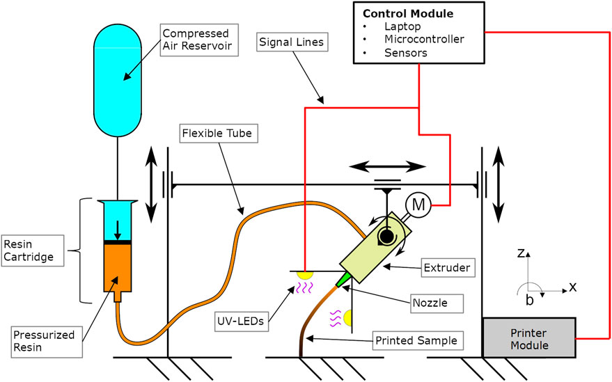
FIGURE 1. Schematic representation of the experimental setup.
The printing process is monitored by three cameras. The first records the entire printing area (Overview Camera). The second only the area around the nozzle (Detail View Camera). The same field of view as with the Detail View Camera is covered by a thermal imaging camera (Thermal View). Both the Detailed View and the Thermal View cameras follow the movement of the printer in order to ensure that the same section of the nozzle is always captured (see Figure 2). All control tasks of the experiments are performed by a computer. By using an external board connected to it, the control signals are accessible via an Input/Output peripheral card. A second computer is used to store environmental data from the sensors and camera images from the Detail View and Thermal View cameras. The sensors are for the documentation of the current g-acceleration values, barometric pressure, relative humidity and air temperature. The recorded sensor data is given a current time stamp.
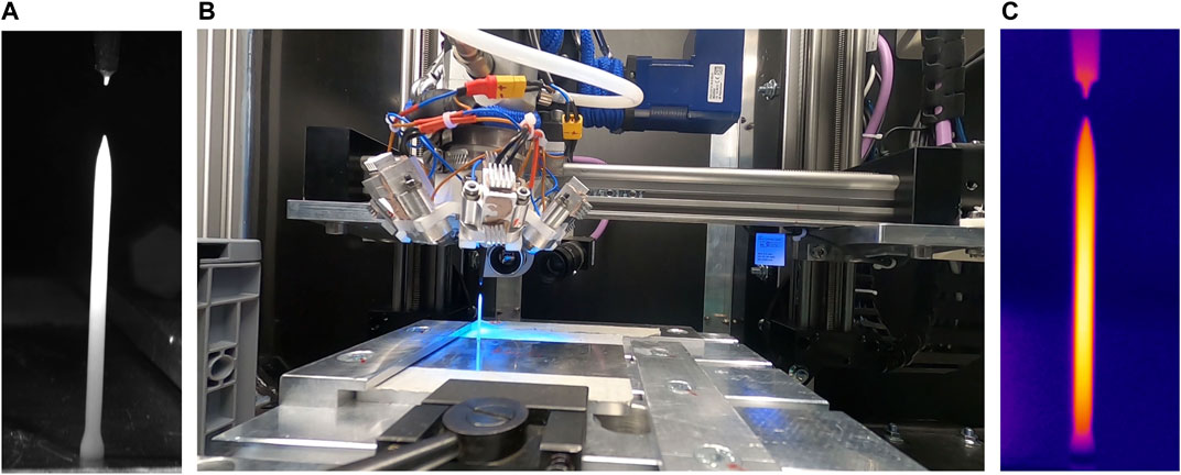
FIGURE 2. Images taken by all three cameras at a given moment. (A) Detail View Camera. (B) Overview Camera. (C) Thermal View Camera.
The control variables of the printing process are explained in detail below:
The feedrate defines the speed at which the printhead moves in the x- and z-directions.
In the experimental setup, nine LEDs are arranged in a circle around the nozzle. Each LED has a radiant flux of 1,450 mW with a peak-wavelength of 365 nm. The LED power can be varied between 0 and 100%. To obtain the absolute irradiance power
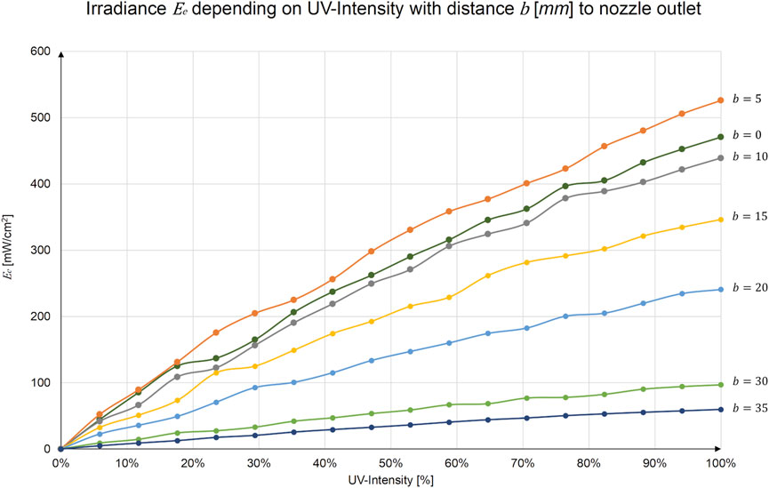
FIGURE 3. Irradiance depending on UV-Intensity and distance to nozzle outlet.
The extrusion parameter corresponds to the amount of material (resin) that is extruded through the nozzle. This amount of material is specified per millimeter of rod length. This also corresponds to the distance traveled by the printhead during material extrusion. Thus, the unit is given in millimeters.
By using conical nozzles, the flow cross-section varies during the transition from the extruder to the nozzle outlet. Therefore, the extrusion value needs to be compensated with the extrusion factor.
For all experiments, an inner nozzle diameter of
Three parabolic flights with 31 parabolas each were performed for this purpose as part of the 73rd ESA Parabolic Flight Campaign (PFC). The experiments were performed during the microgravity phase, which lasts approximately 22 s per parabola. Before and after this microgravity phase, there is a hyper-gravity phase at approximately 1.8 g for around 20 s (Air Zero G, 2022)4.
Additional experiments were performed during the 74th Partial-G Campaign with 0.16 g equivalent to lunar gravity and 0.38 g equivalent to Martian gravity. For the complete evaluation, comparison experiments under 1 g conditions were carried out at the Munich University of Applied Sciences (HM).
In the following sections, the experiments and the methodology used for the analysis are presented. All experiments performed during the parabolic flights are provided in the Supplementary Materials. In order to distinguish the different result sets, the campaign number (73rd or 74th PFC), the flight number (Fxx) and the parabola number (Pxxx) are provided for each experiment. A detailed description of all experiments can be found in the Experiment Report5 of the campaign (Kringer et al., 2021).
During the parabolic flights, the experiments were exposed to external environmental influences. The ambient temperature, the barometric pressure in the experiment enclosure and the relative humidity were all recorded and documented via sensors during the flights. On average, the ambient temperature during the flights was 25°C with 26% relative humidity and an air pressure of 850 hPa. The g-forces also varied during the flights. However, in general the g-forces remained between ±0.05 g6 (European Space Agency, 2022).
The control statements for the experiments were written in G-code, with which all control tasks of the printing unit were carried out. In order to obtain a high degree of comparability between the experiments, a standard procedure was developed for the implementation of all experiments.
During the experiments of the first campaign (73rd PFC), it was observed that the separation of a printed rod from the nozzle did not occur as expected. Therefore, a negative extrusion command was inserted at the end of each experiment to remove excess material. In addition, a post curing of 10 s was implemented to increase the degree of curing of the printed elements (see Figure 4).
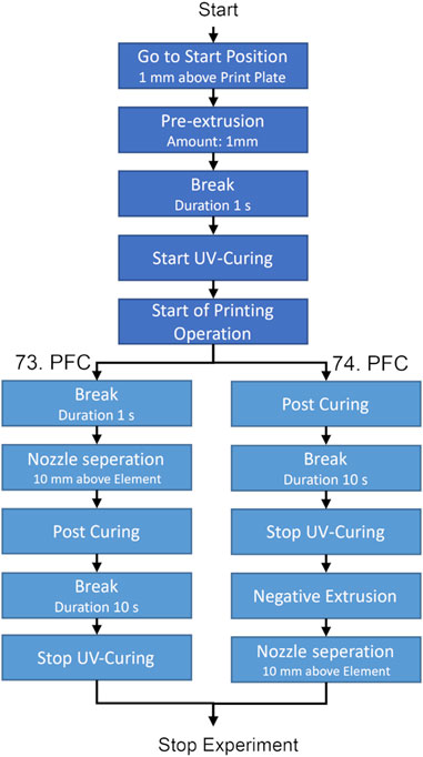
FIGURE 4. Standard procedure of experiments during 73rd and the 74th PFC.
For the geometric evaluation all performed experiments were examined7 using the footage recorded by the Overview Camera. The aim is to document each geometric structure manufactured under zero-gravity, lunar gravity and Martian gravity conditions.
With this evaluation, the feedrate at which the single rods can be printed until they collapse under its own weight was examined. The time up until which the rod starts to collapse is measured. By measuring the time, the successfully printed length can then be calculated based on the set printing speed. Since the UV-light intensity throughout the experiments is kept constant, increasing or decreasing the feedrate has a direct influence on the curing time of the printed element.
The experiments for this evaluation were performed during the 73rd PFC respectively the 1 g comparison rods were printed in the laboratory of the HM. The rods printed for the experiments start from a printing plate in the positive z-direction. The printed element adheres to the printing plate but can be removed for sample storage by hand. The feedrate varied from experiment to experiment. A new nozzle was used for each experiment to keep the ambient and initial conditions as constant as possible. Due to the small number of samples, the result should only be considered in a qualitative manner.
The behaviour of the diagonally printed rod experiments was investigated under zero-gravity and 1 g. During the experiments, the feedrate as well as the angle of the printing trajectory relative to the printing plate were varied.
The experiments were first used to investigate the behaviour of the diagonally printed structural elements in zero-gravity. Since the trajectory of the printer does not correspond to the direction of the outflow from the nozzle, a shear flow was expected. It was therefore also investigated whether this shear flow had an influence on the printing process. For this purpose, the “Diagonal Rod” experiments with an angle of 0° relative to the printing plate were analyzed in detail (cf. 73rd PFC F2 P25, P30).
In order to account for the influence of gravity on the process, a 1 g comparison experiment was also carried out. For this, diagonal rods were printed with an angle of 45° with respect to the printing plate. The influence of gravity was made visible by gradually increasing the printing speed.
The curing zone is the area from the exit of the nozzle to the beginning of the solidified element. Due to the exothermic reaction taking place during the curing process, this area can be easily observed with the Thermal View camera which has also been demonstrated by Garra et al. (Garra et al., 2018). The length of the curing zone depends on both UV-light intensity and feedrate. The length of the curing zone under zero-gravity, 0.16, 0.38 and 1 g of the “Straight Rod” experiments was investigated in detail, where the objective was to determine the maximum length of the curing zone before static problems started to affect the printing process.
The examination was carried out using the images from the Thermal View camera. After 5 s printing time, the distance from the nozzle to the 40°C zone was measured by using the imaging software of the thermal camera and documented (see Figure 5). The temperature limits were selected based on previous experiments with this particular printing material. A typical observation using the Thermal View camera during the experiments as shown in Figure 5 indicates a gel-like state at 40°C. For this evaluation however it should only be an indicator that the curing zone of 40°C can be shifted under lower gravity without resulting a collapse of the structural element.
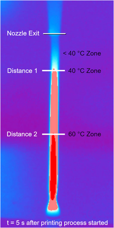
FIGURE 5. Measurement of the distance of the curing zone from the nozzle exit to the beginning of the different temperature zones.
In this chapter, the results of the evaluation of the parabolic flight campaigns and the comparative reference experiments performed under 1 g are presented.
Figure 6A–G shows the geometries that could be produced successfully under zero-gravity. Only the experiment shown in Figure 6H could not be printed successfully in zero-gravity but was successfully carried out under 0.38 g conditions. The individual experiments and their parameters can be taken from the parabola plan (see Supplementary Material). Note that in Figure 6G,H the background has been removed for better visibility of the samples. The original sub-figures of Figure 6 can be found in the Supplementary Material section.
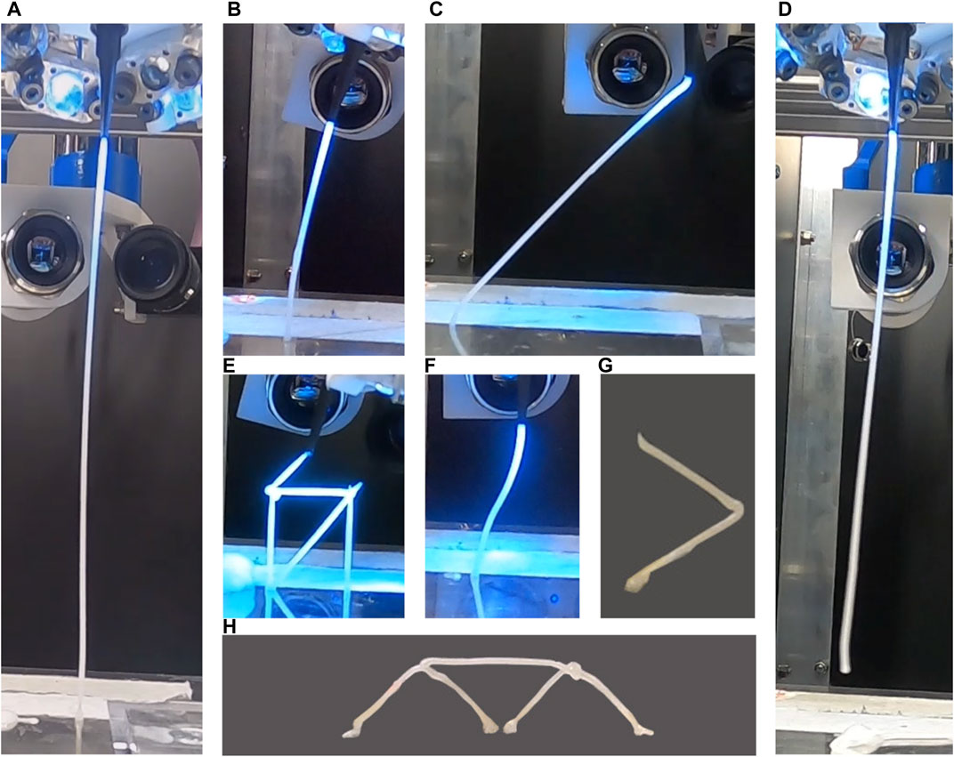
FIGURE 6. Summary of geometries manufactured under zero and altered gravity. (A) Straight rod. (B) Rod with angle - nozzle in line with extrusion direction. (C) Diagonal rod - nozzle perpendicular to printing plate. (D) Free floating rod. (E) Truss element. (F) Free-form element - nozzle in line with extrusion direction. (G) Zig-Zag element. (H) Bridge element consisting of two triangles and one horizontal rod.
The individual geometries which were printed under zero-gravity are explained subsequently. Figure 6A shows a straight rod printed under 0 g (cf. 73. PFC F1 P10). In Figure 6B a rod which was printed with an angle can be seen (cf. 73. PFC F1 P18). For this purpose, the print head was tilted after printing a 20 mm straight section to avoid a shear flow of the resin following to the nozzle exit plane. Figure 6C is a diagonal printed rod with an angle of 45° relative to the printing plate (cf. 73. PFC F2 P27). More details on this set of experiments is featured in chapter 3.3. Figure 6D shows a free-floating rod which has no connection to the printing plate (cf. 73. PFC F1 P26), as it was extruded from the nozzle directly into the free printing area. Figure 6E shows a full truss structure printed during the microgravity phases of 5 subsequent parabolas (cf. 73. PFC F3 P16 - P20). Figure 6F depicts a free-form element. For this print, the nozzle exit was continuously kept in line with the trajectory of the printer by turning the printhead accordingly. Figure 6G shows a zig-zag shaped rod (cf. 74. PFC F1 P20), whose unique feature is the change of direction during the print. Figure 6H is the only geometry from this set of pictures which was only printed successfully in 0.38 g. It consists of two triangles and one bridge which were printed in a single motion throughout three parabolas (cf. 74. PFC F3 P13-P15). During the production of these triangles, there was one side of each triangle where the printing trajectory and therefore the nozzle was moving towards the printing plate. It is assumed that during this trajectory the extruded material has accumulated around the nozzle outlet in 0 and 0.16g, causing the nozzle to become clogged. With the higher gravity component in nozzle direction, it is expected that the extruded material is pulled away from the nozzle outlet and therefore no settlement of material could happen.
The straight rod experiments performed in zero-gravity could be successfully printed until they reached their maximum length after 13 s of total experiment time. This could also be observed for higher printing speeds ranging from 400 to 600 mm/min.
The same experiments under 1 g conditions show that the printed rods remain only stable up to a certain printing time until they collapse. The printing time until the rods collapse, was measured, and is shown in Figure 78. Similarly, the printing time of the successfully printed rods under zero-gravity conditions are included in Figure 7. An increase in the successfully printed length under 1 g conditions at lower printing speeds can be seen in the graph below. It is only when the feedrate is reduced to 250 mm/min that the same rod lengths under 1 g conditions can be achieved as for under 0 g conditions. Note that due to the limited number of parabolas these results are not statistically representative as only one experiment with the same setting was performed. However, it shows the beneficial influence of zero-gravity on the printing process qualitatively.
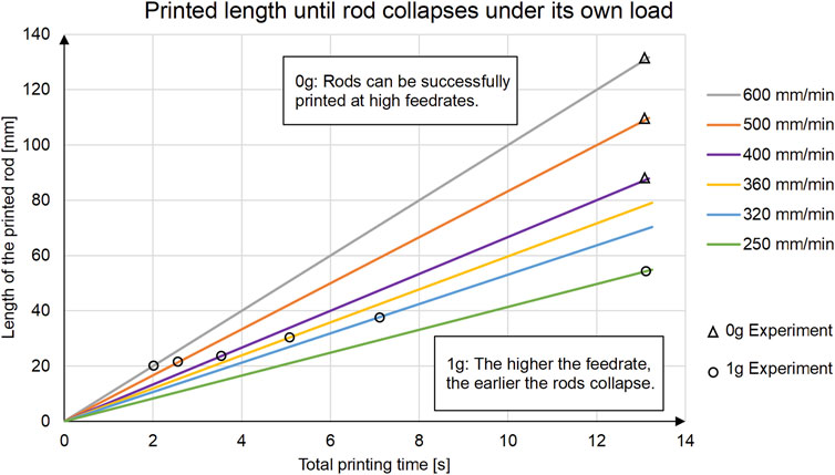
FIGURE 7. Comparison between zero-gravity and 1 g straight rod experiments at different feedrates (73rd campaign).
Figure 8A–E shows the experiments which were carried out under zero-gravity at a feedrate of 400 mm/min. It is remarkable how precisely the rods follow the trajectory of the printer at this speed. Angles between 60° and 0° with respect to the printing plate could be created. To illustrate the influence of microgravity on diagonally printed rods, comparative experiments under 1 g were carried out. These can be seen in Figure 9A. In Figure 9B the same experiment is shown with a significantly higher feedrate at zero-gravity conditions (cf. 73. PFC F2 P27). For the 1 g comparison, a set of diagonal rods were printed at an angle of 60° relative to the printing plate. The printing speed was increased by 40 mm/min increments, starting at 120 mm/min. A significant gravitational influence can already be observed at a printing speed of 200 mm/min. In contrast, the test in zero-gravity could be carried out at a printing speed of 400 mm/min without any observable geometric deviation.
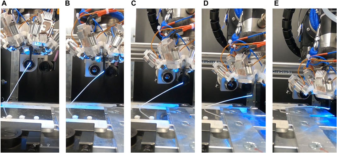
FIGURE 8. (A–E)—Diagonally printed rods in zero-gravity with different angles with regard to the printing plate (cf. 73. PFC F2 P25-P30). (A) 60°. (B) 45°. (C) 30°. (D) 15°. (E) 0°.
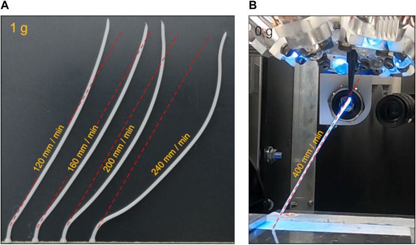
FIGURE 9. (A) Diagonally printed rods under 1 g with an angle of 60° at different feedrates (B) Equivalent experiment under zero-gravity performed at much higher feedrate (cf. 73. PFC F2 P26).
In a more detailed analysis of the nozzle outflow, further diagonal rod experiments were carried out, where an extreme angle of 0° with respect to the printing plate was defined. Figure 10 shows that a higher printing speed increases the offset between the printed element and the nozzle exit plane. However, the influence of this effect on the process can be considered marginal.
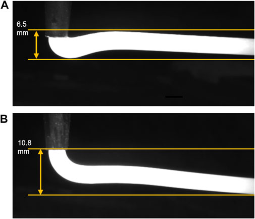
FIGURE 10. Comparison of shear flow (A) Feedrate 200 mm/min (cf. 73rd PFC F2 P25) (B) Feedrate 400 mm/min (cf. 73rd PFC F2 P30).
To illustrate the influence of the curing zone, experiments were carried out at zero-gravity and 0.16 g, where the UV-light intensity parameter was set to between 0 and 30% (cf. 74. PFC F3 P21-30). Figure 11 shows a rod successfully printed under zero-gravity with a UV-light intensity of 0%. This experiment shows that the resin can be extruded in a rod shape without curing at zero-gravity and thus remains in a viscous state. Based on the evaluation of the thermal images, a qualitative diagram was created which shows the maxima of the length of the curing zones (see Figure 12)9. For this, the length of the curing zone (position of the 40°C after 5 s) was evaluated at 0.16, 0.36 and 1 g. In zero-gravity, however, no curing must occur to successfully print a rod element like shown in Figure 11, as the rod can be extruded in the liquid state and remain geometrically stable. Therefore, no length of a curing zone can be measured what brought to the assumption to extrapolate the graph to divert towards infinity.
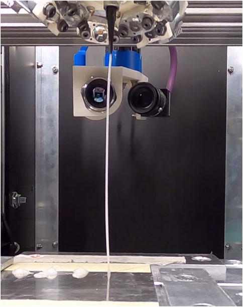
FIGURE 11. Rod printed in zero-gravity without getting cured (UV light Int.: 0%), (cf. 74. PFC F3 P24).
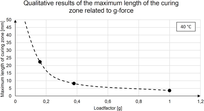
FIGURE 12. Qualitative plot of the maximum length of the curing zone related to g-force.
It was shown that all planned geometric elements could be printed during the flight campaigns. The concern that the liquid resin would not form a rod under zero-gravity conditions due to its surface tension was alleviated. The successful manufacturing of small truss structures also demonstrated that connecting single printed rod elements is possible. The elements required for this were already cured sufficiently to survive the hyper-gravity phase before and after each zero-gravity phase during the parabolic flights, although fully resin cure is only achieved after 24 h according to the manufacturer (DELO Technical Information, 2022).
The optical evaluation of the straight rods supports the hypothesis that a longer viscous section of the curing zone can be obtained with lower gravity. This can be explained by the fact that, in the absence of gravity, the inherent weight of the printed element must no longer be supported by the already printed and cured rod below. Based on this result, the data can serve for a parameter selection of future experiments in zero-gravity as significant higher printing speeds are possible compared to 1 g. The results of the diagonally printed rods in zero-gravity show that, unlike the 1 g experiments, the rods can follow the trajectory of the printer very well, even at higher printing speeds. It turned out that, contrary to previous concerns, a shear flow does not appear and therefore high diagonal angles can be printed very well. In addition, it was shown that, with lower gravity, the curing zone can be longer because the static load due to the inherent weight of the printed element also decreases. However, it was not expected that, under zero-gravity, it would be possible to print an uncured rod element. Thus, the curing length of the zone can be assumed to be infinite under these conditions. The fact that the resin can be printed in zero-gravity in its liquid form allows the joining of two rod elements, both in a liquid state. If the joined elements are cured together, a complete polymerization of both elements will result in a homogeneous structure. A joint created with an already cured rod element can only result in an adhesive bonding between the two elements. This is expected to result in significantly poorer mechanical properties.
The DREPP technology has been selected and investigated in detail because of its versatility and low energy demand because it is expected that this is of particular importance for its use as an ISM technology. According to Bhundiya et al., 2022 the energy demand for melt-based processes of polymers is between 5 and 8 MJ/kg, where the FFF technology is included, and 3.6 MJ/kg for pultrusion of CF/PEEK. For plastic deformation of polymers, the lowest energy demand identified is 0.05–1 MJ/kg (Bhundiya et al., 2022).
In order to be able to compare the DREPP technology with the values of Bhundiya et al., 2022 in terms of its energy requirement, the following formula was developed to describe how much energy is required for curing 1 kg of resin.
Thereby P/A is the curing power in [W/cm2], t the irradiation time [s], D the layer thickness to be cured [cm] and ρ the material density [g/cm³]. With η [-] the efficiency of the light source as well as irradiation losses, are taken into account. If the manufacturer’s data sheet values for DELO GE680 are used and an efficiency of 10% is assumed for the LEDs, this results in a specific energy demand of about 0.02 MJ/kg. If, as in the MERL concept stated, sunlight is used as the UV light source, the energy requirement can be reduced even further.
Since the pure effect of weightlessness on the process, as described in this paper, has been already investigated, the influence of vacuum is now of particular interest. Therefore, the DREPP process will be investigated under approximated space conditions in November 2022. For this purpose, a simplified experiment setup was implemented within the AIMIS-REXUS project at the HM, which will be launched to an altitude of approximately 90 km within a sounding rocket. Due to the parabolic flight path of the rocket, microgravity and a significantly reduced air pressure (less than 0.5 mbar) prevail for 90 s during the flight. The aim of the experiment is to produce four rod-shaped samples (∼4 mm diameter, ∼ 60 mm length) during this flight phase. After recovery of the rocket, the samples are then to be examined. The aim is to determine whether the environmental conditions have a qualitative influence on the manufacturing process.
The potential utilization of the DREPP process is numerous. As, for example, shown in Figure 13 a combination of layer-by-layer and directly 3D-extruded rods could be used to produce a truss inspired boom under laboratory conditions. As the material does not have to be heated in order to be brought into shape and is initially present in liquid form, it is comparatively easy to embed cables for electrical signals, small pipes for fluids or continuous reinforcement fibres in the extrusion process. Especially due to the use of reinforcement fibres, it should be possible to produce light and at the same time rigid composite truss structures. Even smart structures are conceivable to be manufactured with the DREPP technology that are able to change their shape based on environmental conditions (Wang et al., 2018; Zhang et al., 2019). In order to enhance the potential applications with the DREPP-process further research and development will take place at the HM, to implement a manufacturing process capable of producing different structures in open space.
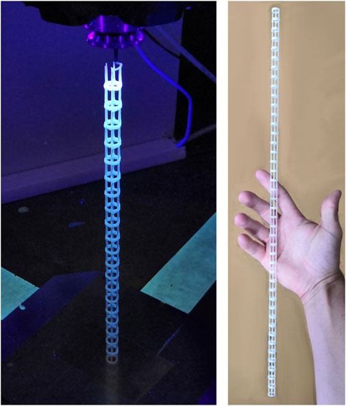
FIGURE 13. Structure made from a combination of layer-by-layer for the horizontal sections and three-dimensional rod elements for the vertical sections.
The original contributions presented in the study are included in the article/Supplementary Material, further inquiries can be directed to the corresponding author.
This article is based on the experiments and collected data of the AIMIS-FYT project. AIMIS-FYT was launched as a student team in 2019 by MK, CB, and MF to demonstrate a 3D-printing process in microgravity. For this purpose, the team successfully participated in two parabolic flight campaigns as part of ESA Fly-Your-Thesis 2020 student program. The initiator and team’s supervisor was MP, who has been promoting this topic at MUAS since 2017. MK was teamleader at AIMIS-FYT and developed the evaluation methods to come to the results which are publicized with this article. CB investigated and provided the parameters used for the experiments during the flights. MF did the mechanical design of the experimental set-up as well as the software design of the datalogging. All AIMIS-FYT members worked together before, during and after the flights to generate this data. Within the AIMIS-REXUS student team, founded in 2018, JP co-developed the sounding rocket experiment to be launched in November 2022.
This study was made possible by the European Space Agency selecting the experiments for the Fly Your Thesis! student program. The article was funded by Deployables Cubed GmbH (DCUBED) and by the European Space Agency under a co-funded research program (ESA contract number 400013618721/NL/GLC/my). The funders were not involved in the study design, collection, analysis, interpretation of data, the writing of this article or the decision to submit it for publication.
A special thanks to MP (Munich University of Applied Sciences) for initiating and motivating the foundation of the AIMIS-FYT student team. Through his support the successful experiments during the parabolic flights and this article became possible. The authors would like to thank also Nigel Savage and Emmanuelle Aubert (ESA Education) for the support throughout the FlyYourThesis! 2020 project, Thibault Paris (Novespace) for the engineering support as well as the laboratory support team at the Munich University of Applied Sciences Christian Leupolz, Mathias Unterreiner and Helmut Steinhögl. For the final review we want to thank Ambre Raharijaona (Deployables Cubed GmbH).
The authors declare that the research was conducted in the absence of any commercial or financial relationships that could be construed as a potential conflict of interest.
All claims expressed in this article are solely those of the authors and do not necessarily represent those of their affiliated organizations, or those of the publisher, the editors and the reviewers. Any product that may be evaluated in this article, or claim that may be made by its manufacturer, is not guaranteed or endorsed by the publisher.
The Supplementary Material for this article can be found online at: https://www.frontiersin.org/articles/10.3389/frspt.2022.899242/full#supplementary-material
1[Webpage] www.massivit3d.com.
2[Datasheet]: https://www.delo-adhesives.com/us/service-center/downloads/downloads/datasheet/DELO%20KATIOBOND_GE680_TIDB-en.pdf?type=5001.
4Explanation of parabolic maneuver: https://www.airzerog.com/zero-g-flights-how-it-works/.
5Experiment Report of AIMIS-FYT: https://esamultimedia.esa.int/docs/edu/AIMIS-FYT_Experiment_Report_v5_Public.pdf.
6Fluctuations in g-level: https://www.esa.int/Education/Fly_Your_Thesis/Fluctuations_of_g_level_and_mechanical_vibrations.
Air Zero G (2022). How it works. Available at: https://www.airzerog.com/zero-g-flights-how-it-works/(Accessed: February 17, 2022).
Bhundiya, H. G., Royer, F., and Cordero, Z. (2022). Engineering framework for assessing materials and processes for in-space manufacturing. J. Materi Eng Perform. doi:10.1007/s11665-022-06755-y
Darling, C., and Smith, D. A. (2021). Syringe pump extruder and curing system for 3D printing of photopolymers. HardwareX 9, e00175. doi:10.1016/j.ohx.2021.e00175
DELO Technical Information (2022). DELO katiobond GE680. Technical Datasheet. Available at: https://www.delo-adhesives.com/us/service-center/downloads/downloads/datasheet/DELO%20KATIOBOND_GE680_TIDB-en.pdf?type=5001 (Accessed: March 16, 2022).
European Space Agency (2022). Fluctuations of g level and mechanical vibrations. Available at: https://www.esa.int/Education/Fly_Your_Thesis/Fluctuations_of_g_level_and_mechanical_vibrations (Accessed: February 17, 2022).
Festo, A. G., and Co, K. G. (2016). 3D Cocooner: Bionic lattice structures from the robotic spinneret. Available at: https://www.festo.com/PDF_Flip/corp/Festo_3DCocooner/en/files/assets/basic-html/page-1.html (Accessed 06 21, 22).
Garra, P., Bonardi, A.-H., Baralle, A., Al Mousawi, A., Bonardi, F., Dietlin, C., et al. (2018). Monitoring photopolymerization reactions through thermal imaging: A unique tool for the real-time follow-up of thick samples, 3D printing, and composites. J. Polym. Sci. Part A Polym. Chem. 56 (8), 889–899. doi:10.1002/pola.28965
Gibson, I., Rosen, D., Stucker, B., and Khorasani, M. (2021). Additive manufacturing Technologies. Cham: Springer International Publishing.
Harbaugh, J., and Dunbar, B. (2022). On-orbit servicing, assembly, and manufacturing 2 (OSAM-2). Available at: https://www.nasa.gov/mission_pages/tdm/osam-2.html (Accessed: June 24, 2022).
Hoyt, R., Cushing, J., Slostad, G., Jimmerson, St.J., and Slostad, J. (2014). “Trusselator: On-orbit fabrication of high-performance composite truss structures,” in AIAA SPACE 2014 Conference and Exposition, 4-7 August 2014 (San Diego, CA: American Institute of Aeronautics and Astronautics). doi:10.2514/6.2014-4337
Kirkman, D., van der Merwe, A., and Campbell, I. (2020). System development for the five-AXIS extrusion of a photopolymer. Sajie 31 (3), 2448. doi:10.7166/31-3-2448
Kringer, M., Böhrer, C., Frey, M., and Schaefer, T. (2021). Fly your thesis!” 2020 experiment Report. Available at: https://esamultimedia.esa.int/docs/edu/AIMIS-FYT_Experiment_Report_v5_Public.pdf (Accessed: March 16, 2022).
Levedahl, B., Hoyt, R. P., Silagy, T., Gorges, J., Britton, N., and Slostad, J. (2018). “Trusselator technology for in-situ fabrication of solar array support structures,” in 2018 AIAA Spacecraft Structures Conference, 8–12 January 2018 (Kissimmee, Florida: American Institute of Aeronautics and Astronautics). doi:10.2514/6.2018-2203
Madry, S. (2020). Disruptive space technologies and innovations. Cham: Springer International Publishing.
McGuire, T., Hirsch, M., Parsons, M., Leake, S., and Straub, J. (2016). “Design for an in-space 3D printer,” in Sensors and Systems for Space Applications IX, 17 April 2016 (Baltimore, Maryland, United States: SPIE). doi:10.1117/12.2223536
Mitsubishi Electric Corporation (2022). Mitsubishi electric develops technology for the freeform printing of satellite antennas in outer space. Available at: https://www.mitsubishielectric.com/sites/news/2022/pdf/0517.pdf (Accessed May 24, 2022).
Prater, T., Werkheiser, N., Ledbetter, F., Timucin, D., Wheeler, K., Snyder, M., et al. (2019). 3D printing in zero G technology demonstration mission: Complete experimental results and summary of related material modeling efforts. Int. J. Adv. Manuf. Technol. 101 (1-4), 391–417. doi:10.1007/s00170-018-2827-7
Reiss, P., Breunig, E., Zimmerhakl, P., Newie, N., and Zeiner, A. (2011). “Investigating new space structures with the FOCUS experiment,” in 20th ESA Symposium on European Rocket and Balloon Programmes and Related Research, 22 May October, 2011 (Hyére, France: Technische Universität München).
Sacco, E., and Moon, S. K. (2019). Additive manufacturing for space: Status and promises. Int. J. Adv. Manuf. Technol. 105 (10), 4123–4146. doi:10.1007/s00170-019-03786-z
Sarantinos, N., Loginos, P., Charlaftis, P., Argyropoulos, A., Filinis, A., Vrettos, K., et al. (2019). Behavior of photopolymer fiber structures in microgravity. SN Appl. Sci. 1 (12), 1693. doi:10.1007/s42452-019-1632-8
Wang, J., Xue, Z., Li, G., Wang, Y., Fu, X., Zhong, W.-H., et al. (2018). A UV-curable epoxy with "soft" segments for 3D-printable shape-memory materials. J. Mat. Sci. 53 (17), 12650–12661. doi:10.1007/s10853-018-2520-0
Yerazunis, W., Weiss, A., Radyjowski, P., and Cottrell, R. (2019). “On-orbit additive manufacturing of parabolic reflectors via solar,” in 70th International Astronautical Congress (IAC), October 31, 2019 (Washington D.C., United States: Mitsubishi Electric Research Laboratories).
Keywords: in-space manufacturing, 3d-printing, parabolic flights, fly your thesis!, microgravity, photopolymer extrusion, UV-curing, additive manufacturing
Citation: Kringer M, Böhrer C, Frey M, Pimpi J and Pietras M (2022) Direct Robotic Extrusion of Photopolymers (DREPP): Influence of microgravity on an in-space manufacturing method. Front. Space Technol. 3:899242. doi: 10.3389/frspt.2022.899242
Received: 18 March 2022; Accepted: 14 July 2022;
Published: 23 August 2022.
Edited by:
Advenit Makaya, European Space Research and Technology Centre (ESTEC), NetherlandsReviewed by:
Paolo Milani, University of Milan, ItalyCopyright © 2022 Kringer, Böhrer, Frey, Pimpi and Pietras. This is an open-access article distributed under the terms of the Creative Commons Attribution License (CC BY). The use, distribution or reproduction in other forums is permitted, provided the original author(s) and the copyright owner(s) are credited and that the original publication in this journal is cited, in accordance with accepted academic practice. No use, distribution or reproduction is permitted which does not comply with these terms.
*Correspondence: Michael Kringer, bWljaGFlbC5rcmluZ2VyQGhtLmVkdQ==
Disclaimer: All claims expressed in this article are solely those of the authors and do not necessarily represent those of their affiliated organizations, or those of the publisher, the editors and the reviewers. Any product that may be evaluated in this article or claim that may be made by its manufacturer is not guaranteed or endorsed by the publisher.
Research integrity at Frontiers
Learn more about the work of our research integrity team to safeguard the quality of each article we publish.