 Seyyed Mohammad Ali Noori Rahim Abadi
 P. Hagqvist
 F. Sikström
 I. Choquet
- 1Department of Engineering Science, University West, Trollhättan, Sweden
- 2Procada AB, Trollhättan, Sweden
Additive manufacturing of parts on-site in space requires investigating the feasibility of adapting to zero-gravity and near-vacuum conditions, a technology applied today on Earth at standard conditions. While a few studies have been conducted for powder bed fusion, a feasibility study remains to be explored for direct energy deposition using a laser beam and a metal wire. This is the purpose of this study, which is conducted using a modeling approach based on computational fluid dynamics. The simulation model developed includes melting, re-solidification, vaporization, prediction of beam energy absorption as a function of the local surface temperature and curvature, ray tracing, tracking of free surface deformation and metal transfer, and wire-resistive heating. The study is carried out by starting from process parameters suited for stable on-Earth metal deposition. These conditions were also studied experimentally to validate the simulation model, leading to satisfactorily results. A total of three other test cases with ambient pressure lowered down to near-vacuum and/or gravitation down to zero are investigated. It is found that, compared to on-Earth conditions, in-space conditions can induce vaporization of the metal alloy that is large enough to result in a curvature of the melt pool free surface but too small to lead to the formation of a keyhole. The in-space conditions can also modify the force balance at the liquid melt bridge between the wire and the melt pool, leading to small changes in the curvature and temperature field at the free surface of the wire tip. Among the observed consequences are a small increase of the melt pool length and a small elevation of the bead height. More importantly, for process control, changing to in-space conditions might also affect the stability of the process, which could be assessed through the width of the liquid metal bridge. However, by using appropriate process control to maintain a continuous liquid metal bridge, it is concluded that direct energy deposition of metal using a laser and a wire could be used for manufacturing metal parts in-space in a tempered atmosphere.
1 Introduction
The ability to additively manufacture parts of different materials and qualities is expected to be of significant importance for non-terrestrial applications. The scarcity of refined raw materials and limited supply of spare parts and tools will drive on-site manufacturing. Owing to its simplicity and versatility in turning digital drawings into manufactured objects with high geometrical complexity, additive manufacturing (AM) could serve many of the on-site manufacturing needs (Sacco and Moon, 2019; Williams and Butler-Jones, 2019; Zocca et al., 2019). However, understanding the effect of the non-terrestrial environment on AM is a prerequisite to verify process feasibility and lay the foundation for the development of process control adapted to these adverse conditions. The first experiments for testing AM under conditions that differ from the Earth’s gravity and atmosphere were performed very recently with the so-called Einstein elevator developed by Reitz et al. (2021) to reproduce lunar gravity and orbit or outer space microgravity conditions. These experiments were conducted using a laser beam and a regolith simulant powder bed to investigate the possibility of producing infrastructure components utilizing in situ resources.
Additive manufacturing of metal parts in a non-terrestrial environment would also permit producing tools in situ. Metal processing through fusion was already applied in space in the late 60’s using welding (see (Mladenov et al., 2019) and references therein). Concerning metal AM in such conditions, little is known yet. The two main sets of technologies applied to metal AM on the Earth are based on powder bed fusion (PBF) and directed energy deposition (DED). PBF performs iteratively the selective melting of a thin layer of metal powder, deposited to form a bed, by means of a high power beam. Such a method has been proven in a microgravity environment by using a gas stream instead of gravity to keep the powder in place (Zocca et al., 2019). The use of (high grade) metal powder constitutes a limitation in that its production is a multistage process, which typically requires material melting and atomization along with subsequent sieving. In addition, powder material usage efficiency with PBF is rather limited, which can be problematic when resources are scarce.
For the DED processes, the material feedstock, most often in the form of powder or wire, is instead continuously fed into a melt pool generated by a high energy source. These feedstock types can be combined with various energy sources, including a laser beam (DED-LB/M-DED with a laser beam and metal), electron beam, and electric arc, the former being the most widely used. Laser beams can either be operated in vacuum or in an atmosphere and induce almost no electromagnetic emissions compared to electron beams that necessitate high accelerating voltage. Also, they produce better near net shape accuracy than electric arcs. Therefore, although the low efficiency of converting electrical energy into light might be a drawback, this study promotes laser-directed energy deposition with wire (LDEDw) as a particularly strong candidate for non-terrestrial manufacturing. Compared to powder-based AM, wire-based AM has indeed the advantage of higher material usage efficiency (Ding et al., 2015). Furthermore, a metal wire can be made with relatively simpler equipment and process than a high grade metal powder, such as through re-purposing scrap metal parts by drawing wire from them. The LDEDw technology thus presents several benefits of interest for non-terrestrial applications. However, the effect on LDEDw of low pressure or space-vacuum, of micro- or zero gravity, and of thermal conditions that can change the cooling rates compared to on-Earth applications remains to be understood.
The approach used in this study is modeling and simulation with computational fluid dynamics (CFD). Numerical models for simulation of PBF or DED with powder with considering the on-Earth conditions have been developed during the last years. For instance, Khairallah and Anderson (2014) developed a mesoscopic model (in the in-house code called ALE3D), which was one of the first models for three-dimensional modeling of PBF. It considered the melt pool thermal flow fields including random particle distribution, temperature-dependent material properties, and surface tension. The effect of the thermocapillary (or Marangoni) force, radiation, and recoil pressure were ignored. They simulated selective laser melting processes and showed the importance of considering the stochastic nature of the powder bed, which homogeneous models neglected. Recently, Afrasiabi et al. (2021) proposed a new 2D smoothed particle hydrodynamics (SPH) method for mesoscale simulation of the laser-PBF process. Their new method could decrease the computational cost by 50% through developing a new adaptive refinement method with an optimized neighbor-search approach. This method could thus be used for parametric studies and running high-resolution models with less computational effort. In simulations of laser-DED with powder, the powder injection is often performed either by using a mass source term (Wen and Shin, 2011) or applying streams of particle impinging on the substrate surface (Pinkerton, 2015; Dao and Lou, 2022). The latter approach can consider particle size, velocity, and temperature distributions and also the particle–laser–workpiece interactions. Therefore, the deposited particles pattern and the resulting bead profile can be predicted more accurately. In the recent study by Dao and Lou (2022), this approach was used to study different powder/melt-pool size ratios and reveals the transient characteristics of the thermal flow in the melt-pool. Contrary to PBF and DED with powder, DED with a wire started only recently to be modeled and simulated with CFD.
In order to verify the applicability of LDEDw for non-terrestrial applications, CFD is used in this study. The simulated LDEDw process uses a wire feedstock pre-heated by applying an electric potential between the fed wire and the workpiece (Hagqvist, 2015). Different values of the ambient temperature (Tamb) could be considered depending on the specific application. For instance, Tamb ≈ 3 K in space shadowed from the sun, Tamb ≈ 300 K in a space vehicle, or Tamb ≈ 400 K on the sunny lunar ground. The effect of changing the surrounding temperature is not investigated at this stage. All the studied test cases are at the intermediate ambience that corresponds to room temperature in a space vehicle. The atmosphere, in all cases, is made of a rare gas (argon), and the metal is the alloy Ti-6Al-4V. A total of four sets of process conditions are investigated that differ through the value of the gravity
C1:
C3:
The model is presented in Section 2. The on-Earth conditions of case C1 were also studied experimentally. The computational results are compared to the measurements in Section 3.1. Next, the effect of the gravitation and ambient pressure values on laser–metal interaction, temperature and velocity fields, melt pool, metal transfer, and bead height are compared to discern whether an LDEDw process can be maintained during these conditions and what considerations have to be made for deployment.
2 Mathematical Model Description
The model describes the alloy in solid and liquid state and the gas atmosphere. It predicts the fraction of laser beam energy absorbed by the alloy as a function of the local surface temperature and curvature and multiple Fresnel reflection with a ray tracing approach. It computes the wire resistive heating, alloy melting, net vaporization and re-solidification, fluid flow, free surface deformation, and metal transfer using a Volume of Fluid (VOF) method (Hirt and Nichols, 1981). This model was implemented in the open source computational fluid dynamics software (OpenFOAM) based on earlier developments described in Noori Rahim Abadi et al. (2021) and Noori Rahim Abadi et al. (2022) and references therein. Modeling assumptions that can be found in Noori Rahim Abadi et al. (2021) and Noori Rahim Abadi et al. (2022) are not repeated here. Concerning the main new developments made for this study, it is assumed that the continuum limit still applies to the gas phase when the pressure is as low as 11 Pa (Li et al., 2019; Luo et al., 2019). The fusion enthalpy and the solidus and liquidus temperatures are assumed to undergo a negligible change when changing the ambient pressure. For simplicity, the vaporization of Ti-6Al-4V is modeled as the vaporization of pure titanium since this constituent largely dominates (by 90%) the alloy. The model is summarized in the next section, followed by the material properties and process parameters, and finally the computational domain, boundary conditions, and solution method.
2.1 Governing Equations
A one-fluid approach is applied and the model is made of five partial differential equations governing mass, momentum, (thermal) energy, volume fraction of alloy, and electric potential. Presented in the same order as implemented, these equations are written as follows (Luo et al., 2019; Noori Rahim Abadi et al., 2021; Noori Rahim Abadi et al., 2022):
where t is the time. The primary variables are the metal volume fraction, α; the one-fluid velocity vector,
The remaining terms are now successively defined. Concerning Eq. 1, the third term at the left hand side was introduced by Berberovic et al. (2009) to sharpen the gas–metal free surface. It is active at the free surface alone and depends on the compression velocity,
where M is the molar mass of the alloy, R (= 8.314 J/(mol.K)) is the universal gas constant, and hfg and Tv = Tv(Pamb) are the vaporization enthalpy and temperature, respectively. βr = βr(Pamb) accounts for the re-condensation of the vaporized metal as a function of the ambient pressures, Pamb. This coefficient varies from 1 at a low vaporization rate (i.e., at high ambient pressure or low laser power density) to 0.18 at a high vaporization rate (corresponding to low ambient pressure or high laser power density) (Li et al., 2019; Luo et al., 2019). The values used in this study are given in Table 1. At the left hand side of Eq. 1, the third term is the viscous friction and II denotes the identity matrix. The fourth term is the Darcy-type source term for damping the fluid alloy velocity in the mushy zone where it re-solidifies. It depends on the fraction of liquid alloy, fl = fl(T), that ranges from zero in the solid region to one in the liquid region. This fraction is defined by a continuous function of temperature with continuous derivative (Rösler and Brüggemann, 2011), according to
where Ts is the solidus temperature, Tl is the liquidus temperature, and Tm = 0.5(Ts + Tl) is the arithmetic averaged melting temperature. The constant CD (which is inversely proportional to the permeability of the porous media) and ϵD (that is here to avoid division by zero in the solid phase) are set to 109 and 0.001, respectively. At the right hand side, the second term is the buoyancy force, in which β is the volume expansion coefficient of the alloy in liquid state, ρm = ρm(Tm) is the working material density at the melting temperature, and
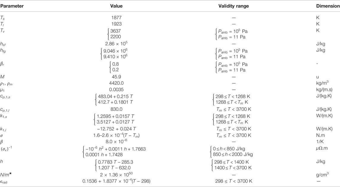
TABLE 1. Material properties of Ti-6Al-4V (Li et al., 2019; Boivineau et al., 2006; Mills, 2002; Fan, 2013; Rai et al., 2009; Wieting and Schriempf, 1976; Desai, 1987).
In the energy equation, the fourth term is related to metal melting and re-solidification and hsf is the latent heat of fusion. The first term at the right hand side is the resistive (or Joule) heating, whereas σϵ = σϵ(T) is the electrical conductivity. The following terms act at the free surface. In the radiative cooling term that follows the vaporization cooling term, ϵrad is the radiative emissivity, σB (= 5.67 × 10⁻⁸ W/(m−2.K−4)) is the Stefan–Boltzmann constant, and Tamb (= 300 K) is the ambient temperature. The laser beam of total power Plaser moves at a travel speed Ulaser along the positive direction x. It has a Gaussian power density distribution (Noori Rahim Abadi et al., 2021),
which is circular here so that the laser spot radius in focus is the same along the x and y axis, thus a = b. The fraction of beam energy locally absorbed,
with
The refractive index,
where
In these expressions, ωp is the plasma frequency, τ is the electron relaxation time, N is the free electron density, e is the electron charge, m* is the optical effective mass of a conduction electron, and ϵ0 is the permittivity of vacuum. The beam wave frequency, ωλ = 2πc/λ, depends on the beam wavelength, λ (= 1.06 μm), and the speed of light in vacuum, c. The material electrical conductivity, σϵ = σϵ(h(T)), is a function of the local temperature at the metal surface through the sensible enthalpy h, see Table 1.
2.2 Material Properties
The one-fluid properties are defined by the following mixture model:
The index s holds for the solid phase and l for the liquid one. The indices 1 and 2 stand for primary (Ti-6Al-4V) and secondary (argon gas) materials, respectively. To our knowledge, there is no database containing all the material properties needed here for the metal alloy. Most of its thermodynamic and transport properties are taken from Mills (2002). The thermal expansion coefficient (β) and the surface tension (σ) are taken from Rai et al. (2009). The properties extracted from other sources are the re-condensation coefficient (βr) (Li et al., 2019), electrical conductivity (σϵ) (Boivineau et al., 2006), radiation coefficient (ϵrad) (Fan, 2013), absorptivity-related parameters (Wieting and Schriempf, 1976), and latent heat of fusion (hsf) and vaporization (hfg) (Desai, 1987). They are given in Table 1 and Table 2 for the shielding gas.
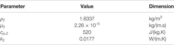
TABLE 2. Material properties of argon gas at 300 K, (Cengel, 2007).
2.3 Computational Domain, Boundary Conditions, and Solution Method
The computational domain used for the simulations is shown in Figure 1. It spans 80 × 9 × 15 mm in the x, y, and z directions, respectively. A 3-mm-thick metal sheet made of alloy Ti-6Al-4V, which is used as a substrate, is located in the bottom of the domain to initialize the computations. The remaining upper part of the domain is filled with argon gas. A filler wire of same alloy and diameter Dw enters the domain from the top surface. It makes an angle, θw, with respect to the x direction and is fed at the velocity Uw. In addition, it is translated along the positive x-direction at the same speed Ulaser as the laser beam. The laser beam of wavelength λ and total power Plaser is tilted by a small angle θlaser with respect to the z-direction to avoid back reflection into the processing optics (an issue that typically has to be considered during LDEDw). At the workpiece surface, the center of the beam spot is at the (offset) distance of 2 mm from the tip of the filler wire. This offset value was selected based on previous experience since it led to a smooth metal transfer through the liquid metal bridge during the deposition at the on-Earth reference conditions of case C1.
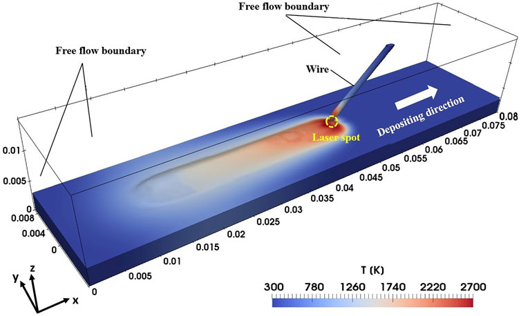
FIGURE 1. Computational domain (sizes are in m).
At the domain boundaries, the alloy is in solid state, at rest, and cooled with natural convection (= 10 W/(m2.K)) and radiation to the atmosphere at Tamb = 300 K. In the atmosphere sub-region, the domain boundaries let the argon gas enter (at Tamb) or exit freely based on the pressure field computed inside the domain. To predict the resistive heating of the filler wire, an electric potential difference is applied between the wire section at the top boundary and the workpiece lower surface. The boundary value of the electric potential is set to reproduce the potential difference (ΔV) experimentally measured in C1 between the wire upper section and its tip on the top surface of the workpiece. In addition, since the geometry has a symmetry about the xz-plane passing through y = 0, only half of the domain is simulated. The process parameters used identically in all the simulations are summarized in Table 3.
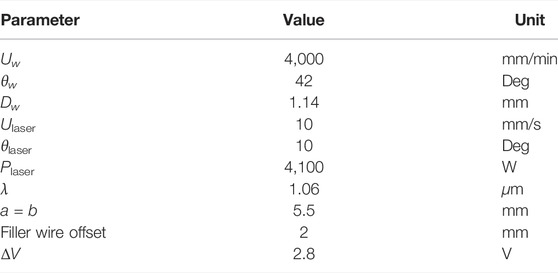
TABLE 3. Process parameters common to all the simulations and experiment.
The computational domain is discretized into cuboid grid cells. The computational results presented in the next section were obtained with an adaptive mesh refinement technique to make the grid finer at the gas–metal interface. Based on the mesh study, the maximum grid size far from the free surface is 1 mm, while it is reduced to 0.25 mm close to the interface.
The solution method is as described in Noori Rahim Abadi et al. (2021) and Noori Rahim Abadi et al. (2022). To achieve a stable solution during solving the highly coupled set of Eqs 1–5, the CFL number is set to 0.04, which leads to a maximum time step size of 10−4 s. The iterations at each time step continue until the residual of each variable is less than 10−10. The simulation time is 4 s, at which the solution has reached quasi-stable condition. This can be confirmed through observing the evolution over time of the volume of liquid alloy (see Section 3) and the thermal flow fields.
3 Results and Discussion
In this section, the model is first tested confronting computational results to experimental measurements for the on-Earth LDEDw process conditions C1. Next, the effect of the ambient pressure with and without the presence of gravitational acceleration is investigated. The impact of these changes on various quantities including the fraction of beam energy absorbed, thermal flow fields, melt pool size, and bead profile after re-solidification are discussed along with their implications for the use of LDEDw for non-terrestrial manufacturing.
3.1 Validation of the Numerical Results
LDEDw induces different heating zones in the workpiece, which result in specific microstructure, and therefore can be used to test the model. Figure 2 compares a macrograph image (left) and computed isotherms (right) obtained with the process conditions C1 defined in Section 1 and in Table 3. The results are presented in a cross section selected in the region where the process is fully-developed. Three different heating zones can be observed. Away from the heat source, the unaffected zone (UZ) has the same microstructure as the original substrate since its temperature did not exceed a value of the order of the α − β transition temperature of the alloy, Tα−β = 1268 K (see the red isoline in Figure 2). On the contrary, close to the heat source, the fusion zone (FZ), delimited in the right side of Figure 2 by the computed melting temperature isoline (in black), results after re-solidification in large grain size that can be seen in the macrograph image (left). In the intermediate region (Tα−β ≲ T ≤ Tm) or heat-affected zone (HAZ), the microstructure is distinct from the UZ and the grain size is smaller compared to the FZ. It can be seen that the results show an excellent agreement between the predictions and experimental data. In addition, the reinforced bead profile after re-solidification is predicted satisfactorily (in blue) compared to the experiment, which confirms that the deposition process is properly simulated by the solver.
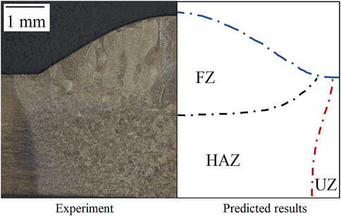
FIGURE 2. Cross-sectional macrograph image (left) and computed isocontours (right) visualizing different heating zones. The dashed-dotted line color and isoline correspondence are blue: α = 0.5, black: T = Tm, and red: T = Tα−β.
3.2 Effect on the Material Heat Input and Heat Loss
Changing the environment from on-Earth to space conditions could change the material ability to absorb beam energy as well as to loose thermal energy through vaporization when performing LDEDw. These two aspects are now analyzed. Figure 3 shows the evolution over time of the average fraction of beam energy absorbed by the alloy. It compares the results computed with each of the process conditions C1–C4. The plots show no significant difference. When t ≥ 1.5 s, the average absorptivity is stabilized and equal to about 0.44 in each of the cases. It implies that, for the reference case C1 studied, the lowering of the atmospheric pressure down to 11 Pa did not result in the transition from conduction to the keyhole mode. In other words, changing the process conditions from on Earth to in-space has an impact on the temperature field and on the deformation of the melt pool free surface (see next sections) that is sufficiently localized and limited in intensity to have little consequences on the average absorptivity.
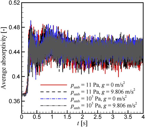
FIGURE 3. Evolution over time of the average fraction of laser beam energy absorbed by the alloy at the different operating conditions C1–C4.
The repartition between the wire and the workpiece of the absorbed laser beam power is now considered. Figure 4 visualizes the evolution over time of the rate of beam energy absorbed by the workpiece and the filler wire for the computed test cases C1–C4. It can be seen that this rate is almost three times larger in the workpiece than in the filler wire. A very similar result is obtained in each of the four cases.
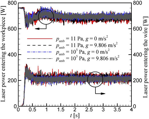
FIGURE 4. Evolution over time of the rate of beam energy effectively absorbed by the wire and by the workpiece at the different operating conditions.
Figure 5 shows the evolution over time of the computed rate of mass loss due to vaporization for the different operating conditions C1–C4. It can be seen that the gravitational acceleration does not have any noticeable effect on vaporisation. This result is expected since the primary effect of changing the gravitational acceleration is on the weight and on the buoyancy force, and not on the thermodynamic properties related to vaporisation. In addition, when present (as on-Earth) the forces related to the gravitational acceleration are known to be of small intensity compared to, for example, the thermocapillary force. Therefore, if they have any indirect effect on vaporisation, this one should be weak. In addition, Figure 5 shows that the ambient pressure has a clear effect on vaporization. At on-Earth pressure no vaporization takes place. Indeed, at this condition, the metal temperature does not reach to the vaporization temperature (= 3637 K), as can be seen in the next section. By reducing the ambient pressure, the vaporization temperature decreases while the latent heat of vaporization increases. Hence, the metal can start vaporizing sooner and result in a larger rate of heat removal per unit mass vaporized at the lower ambient pressure. When the ambient pressure is reduced to 11 Pa, the vaporization temperature is 2200 K, which is low enough for vaporization to occur in the simulations, as can be seen in Figure 5. It can also be observed that at process start, the rate of mass loss due to vaporization first increases sharply up to the time t ≈ 0.3 s, then it decreases suddenly before increasing again. This abrupt variation is related to the distance between the wire and the workpiece. Initially, the wire is not in contact with the substrate and during the simulations multiple beam reflection is observed in the space between them. When the wire and the substrate enter into contact, this space disappears as well as the secondary Fresnel reflections. It results in a sudden lowering of the energy absorbed by the wire that moreover starts to shadow the workpiece. Thus, the variations in power absorbed can be seen in Figure 4 at t ≈ 0.3 s, which in turn affect vaporization.
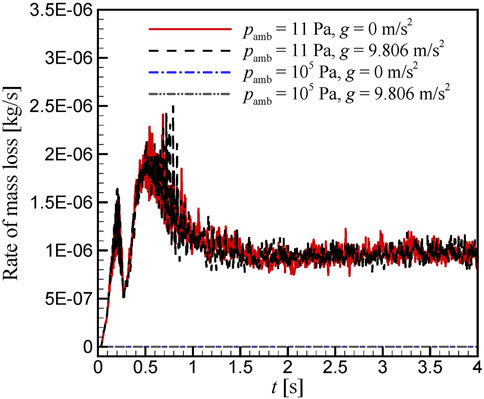
FIGURE 5. Evolution over time of the rate of metal mass loss due to vaporization at different operating conditions.
The results show that at Pamb = 11 Pa the rate of mass loss reaches to a quasi-stable condition when t
The LDEDw process conditions C1–C4 thus lead to very similar mean laser beam heat input into the metal alloy. The near-vacuum conditions C2 and C4 also experience some heat loss by vaporisation, contrary to the Earth’s standard pressure condition.
3.3 Effect on the Thermal Flow
The local effect of changing the ambient pressure and/or the gravitational acceleration on the temperature and velocity fields is now examined at the free surface. Figure 6 shows the melt pool top view at time t = 2 s (i.e., during the transient development) and at t = 4 s (fully developed melt pool). It compares isotherms computed at the two extreme conditions C1 (on-Earth Pamb and g) and C4 (near-vacuum Pamb and 0 g). Looking at the evolution from t = 2–4 s, it is observed that the extent of the melting temperature isotherm Tm (therefore the FZ) shrinks along the travel direction while the isotherms at lower T (thus the HAZ) expand. The former evolution is due to the establishment of re-solidification, and the latter to the development of the diffusion of thermal energy from the liquid to the solid alloy. Comparing at given time the plotted isotherms between the cases C1 and C4, it can be seen that they differ. Differences are also observed with the cases C2 and C3 (as seen in Figure 7 as the melt pool contour is related to the Tm-isoline). They show that a reduction in the ambient pressure (at constant g), results in an elongation of the isotherms toward the negative x-direction. The maximum temperature computed in the melt pool at quasi-steady condition is given in Table 4 for each of the process conditions C1–C4. These data show that when the ambient pressure is lowered while the gravitational acceleration is constant (i.e. C1 → C2 and C3 → C4), the maximum temperature is lowered by ≈ 60 K. This weak cooling is consistent with a weak vaporization. However, it might seem to be in contradiction with the observed melt pool elongation. A second effect of vaporisation is to apply a recoil pressure force on the free surface. The computations show that this force is maximum around the front side of the wire tip, where the temperature is highest (see Figure 6). Its influence on the flow of liquid alloy is discussed with the next figure. In addition, the results show that when the gravitational acceleration is reduced while the ambient pressure is constant (i.e. C1 → C3 and C2 → C4), the isotherms are also elongated in the negative x-direction. Furthermore, the maximum temperature is increased by ≈ 30 K (see Table 4). Possible reasons are highlighted below when examining the results of Section 3.4.
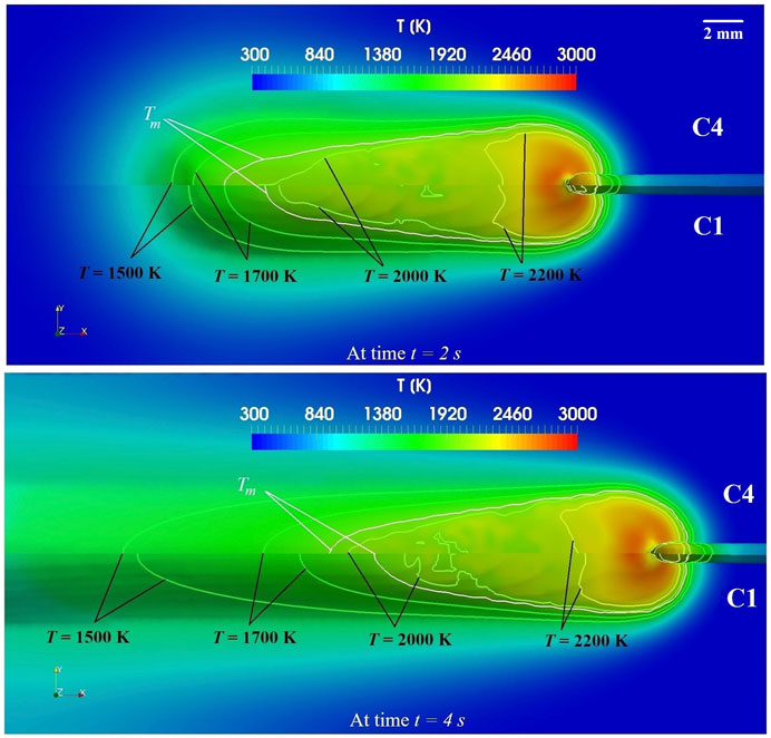
FIGURE 6. Top view of isotherms computed at the workpiece upper surface. Upper image: at time t = 2 s; lower image: at time t = 4 s. Upper sub-images: on-Earth conditions C1. Lower sub-images: in space conditions C4.
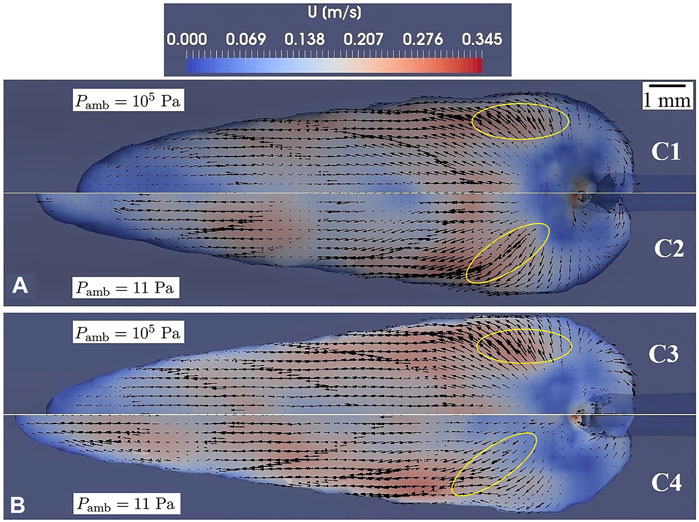
FIGURE 7. Velocity field and vectors at the free surface of the liquid alloy at time t = 4 s for every operating condition; (A)
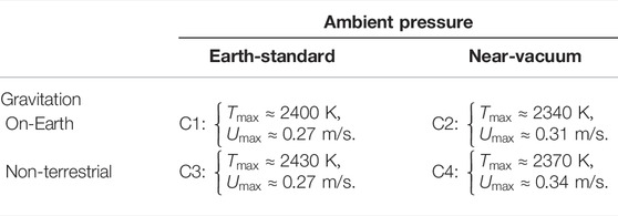
TABLE 4. Maximum velocity (Umax) and temperature (Tmax) in the melt pool at quasi-steady state for the different process conditions.
Figure 7 presents the top view of the melt pool with the velocity field and vectors at the quasi-stable stage (time t = 4 s) for the four different operating conditions. The results show that the flow pattern is very similar when lowering the gravitational acceleration at constant pressure. If instead the pressure is reduced at constant gravitation, some differences are observed in the flow direction, especially in the regions that are marked in the figure. It can be seen that at the atmospheric pressure the flow is stronger toward the lateral edge of the melt pool, while at near-vacuum condition the direction is tilted toward the melt pool rear. Furthermore, the maximum velocity in the liquid alloy is slightly increased when the ambient pressure is decreased at constant g (i.e., C1 → C2 and C3 → C4), as can be seen in Table 4. These differences are explained by the recoil pressure that results from the metal alloy vaporization occurring when the processes are operated at reduced ambient pressure. The recoil pressure force is an import momentum source term at the right hand side of Eq. 3 governing the
When the gravitational acceleration is reduced while the ambient pressure is constant (i.e., C1 → C3 and C2 → C4), the maximum fluid velocity behaves differently depending on the ambient pressure: it is unchanged at Earth-pressure, while it varies with g at near-vacuum condition. A first effect of gravity on convection in the melt pool is through the momentum transferred with metal transfer. The related potential energy is here believed to be negligible as the wire tip is in contact with the pool. A second possible effect could be through the buoyancy force. At standard Earth-pressure, this upward force is known to be negligible compared to the other forces present (Cho et al., 2009). Thus, the unchanged maximum velocity in C1 and C3 is observed. In addition, at near-vacuum condition, the computational results C2 show that the buoyancy force is much lower than the recoil pressure force. It is thus believed that the buoyancy force has no significant contribution to accelerating the liquid alloy.
3.4 Effect on the Thermal Zones and Free Surface Deformation
It has been seen that the ambient pressure and the gravitational acceleration have some effect on the thermal flow field inside the melt pool during the studied LDEDw process. Their impact on the thermal zones and the free surface profile are now considered. The latter is an important aspect for process control as it might affect the stability of the process. Figure 8 presents a top view of the thermal zones during the quasi-stable stage at t = 4 s for the different operating conditions. The plotted outer edge of the HAZ corresponds to the α − β transition isotherm. The results confirm that the length and shape of FZ and the extent of the HAZ within the workpiece increase when the ambient pressure or the gravitational acceleration decrease. These variations in HAZ, which reveal variations in thermal history, might induce small variations in material microstructure.
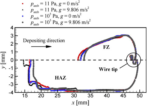
FIGURE 8. Melt pool contour and heat-affected zone at the operating conditions C1–C4.
In Figure 9, the evolution over time of the total volume of liquid alloy at the different operating conditions is shown. This volume becomes almost unchanged after t
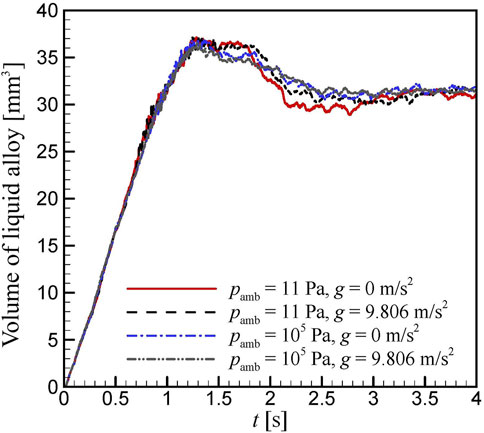
FIGURE 9. Volume of liquid alloy as a function of time at the different operating conditions.
In Figure 10, the computed bead profile is presented after re-solidification for different operating conditions. The results show that the bead width is seemingly unchanged, while the bead surface curvature is slightly more downward at the lateral sides. As expected, the bead height is increased by lowering the ambient pressure or the gravitational acceleration. The highest elevation is reached at near-vacuum and no-gravity condition.
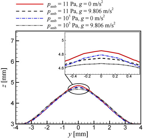
FIGURE 10. Cross section of the bead profile after re-solidification at the different operating conditions.
Figure 11 compares side view plots showing the gas–metal interface at the quasi-steady state for the different operating conditions. At the near-vacuum ambient pressure, vaporization occurs causing the appearance of the recoil pressure effect by which the liquid metal surface is pushed downward, as can be seen in the zoomed image of Figure 11. The displaced liquid metal then moves to the rear region of the melt pool (see Section 3.3) causing the longer melt pool and the relatively higher bead profile. The role of gravity and the resulting buoyancy force is not remarkable in a melt pool, as known from former studies (Cho et al., 2009). However, in the presence of metal transfer from a filler wire, the weight might explain the small increase in curvature observed at the front side of the wire tip (at x ≈ 46.5 mm) at near-vacuum pressure compared to standard on-Earth atmospheric pressure. This small change in curvature results in a small increase of the absorptivity that explains the higher temperature seen at the wire tip when comparing the isotherms between C1 and C4 in Figure 6. Thus, it could explain the small increase in maximum temperature noticed in Table 4 when changing the gravitation from on-Earth to non-terrestrial condition.
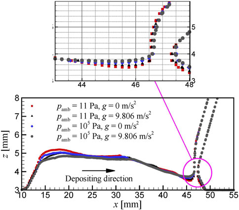
FIGURE 11. Side view of the gas–metal interface at the different operating conditions.
Another important effect observed at the reduced ambient pressure and in the absence of gravity is the thinner width of the liquid metal bridge in the region where the wire tip joins the melt pool free surface. It is most probably a consequence of the lowering of the free surface by the recoil pressure that was previously observed in front of the wire tip. As a result, the distribution of the current density flowing through the contact section for resistive heating of the wire is more constricted, which can lead to a larger Joule heating. The thinner liquid metal bridge implies that the LDEDw process is moving toward more unstable operating conditions. This is supported by the slightly larger irregularities of the volume of liquid alloy observed in Figure 9 at Pamb = 11 Pa and
3.5 Feasibility of LDEDw for On-Orbit Manufacturing
As seen in Figure 11, this CFD-based feasibility study shows that the metal bridge between the wire and the workpiece is maintained in all the cases. This is the most important finding from a process standpoint since the continuous metal transfer is a prerequisite for high material quality and the ability to build multilayer parts successfully (Heralic, 2012). The variations in metal bridge width, build height, and thermal profile are all similar to what an LDEDw control system is made to handle for conventional on-Earth applications (Hagqvist, 2015). This indicates that, by using an appropriate process control to maintain the liquid metal bridge (Kisielewicz et al., 2021), LDEDw can be used for manufacturing metal parts in-space at tempered atmosphere.
4 Conclusion
In this study, the feasibility of performing LDEDw in a tempered atmosphere and at near-vacuum ambient pressure with or without the gravitational acceleration was investigated numerically. A set of process parameters that led to a very stable process at on-Earth pressure and gravity was selected as reference. To simulate the LDEDw at in-space conditions, a solver developed in the OpenFOAM software in former studies was further extended. The predicted results were satisfactorily validated against the experimental data available at on-Earth process conditions. In addition, the following outcomes were obtained through the numerical simulations:
• Metal vaporization can be initiated in LDEDw operated at near-vacuum ambient pressure. Although weak for the studied process conditions, it has several local effects on the process. It has a cooling effect on the liquid alloy temperature due to the transfer of thermal energy to latent heat of vaporisation. It changes the free surface curvature due to the downward force applied by the recoil pressure, resulting in a thinning of the liquid bridge. It locally increases the fluid velocity and changes the flow direction due to the action of the recoil pressure on the fluid momentum. Finally, these effects result in an elongation of the melt pool and an increase of the bead height.
• The absence of gravitational acceleration changes the force balance at the liquid bridge. Although weak, this change leads to a change in curvature of the liquid bridge that results in an increase of the beam energy absorptivity and an increase of the temperature at the wire tip. It results also in an elongation of the melt pool and an increase of the bead height. However, the way the absence of gravitation acts on the thermal flow to increase of the melt pool length remains to be explained.
• With the specified process parameters, LDEDw can be performed at near-vacuum pressure and no gravity condition without transition to a keyhole mode. Although, it moved the process toward a more unstable operating mode by making the liquid–metal bridge thinner, LDEDw is found to be a suitable candidate for tempered in-space manufacturing of metal parts.
Finally, further investigation is needed to evaluate the effect on LDEDw of colder and warmer environments that can be met in, for example, outer space or a sunny lunar ground. If the process needs to be operated in an environment that cannot be tempered, an adjustment of the power input might then be needed.
Data Availability Statement
The raw data supporting the conclusions of this article will be made available by the authors, without undue reservation.
Author Contributions
SR: methodology, software, validation, investigation, visualization, and writing—original draft. PH: conceptualization, and writing—reviewing & editing. FS: conceptualization of experimental approach, validation, investigation, and writing—reviewing & editing. IC: conceptualization of modeling and simulation approach, methodology, validation, investigation, visualization, writing—reviewing & editing, and supervision.
Funding
This research work is supported by grants from the Swedish Knowledge Foundation projects AdOpt (20170315) and SAMw (20170060).
Conflict of Interest
The authors declare that the research was conducted in the absence of any commercial or financial relationships that could be construed as a potential conflict of interest.
Publisher’s Note
All claims expressed in this article are solely those of the authors and do not necessarily represent those of their affiliated organizations, or those of the publisher, the editors, and the reviewers. Any product that may be evaluated in this article, or claim that may be made by its manufacturer, is not guaranteed or endorsed by the publisher.
Acknowledgments
This research work is supported by grants from the Swedish Knowledge Foundation projects AdOpt (20170315) and SAMw (20170060), which is gratefully acknowledged.
References
Afrasiabi, M., Lüthi, C., Bambach, M., and Wegener, K. (2021). Multi-resolution Sph Simulation of a Laser Powder Bed Fusion Additive Manufacturing Process. Appl. Sci. 11, 2962. doi:10.3390/app11072962
Berberovic, E., Van Hinsberg, N. P., Jakirlic, S., Roisman, I. V., and Tropea, C. (2009). Drop Impact onto a Liquid Layer of Finite Thickness: Dynamics of the Cavity Evolution. Phys. Rev. E 79, 036306.
Boivineau, M., Cagran, C., Doytier, D., Eyraud, V., Nadal, M.-H., Wilthan, B., et al. (2006). Thermophysical Properties of Solid and Liquid Ti-6Al-4V (TA6V) Alloy. Int. J. Thermophys. 27, 507–529. doi:10.1007/pl00021868
Cengel, Y. A. (2007). Heat and Mass Transfer: A Practical Approach (SI Units). 3rd edition. New York, NY, USA: McGraw-Hill.
Cho, J. H., Farson, D. F., Milewski, J. O., and Hollis, K. J. (2009). Weld Pool Flows during Initial Stages of Keyhole Formation in Laser Welding. J. Phys. D Appl. Phys. 42 (17), 175502. doi:10.1088/0022-3727/42/17/175502
Dao, M. H., and Lou, J. (2022). Simulations of Directed Energy Deposition Additive Manufacturing Process by Smoothed Particle Hydrodynamics Methods. Int. J. Adv. Manuf. Technol. 120, 4755. doi:10.1007/s00170-022-09050-1
Desai, P. D. (1987). Thermodynamic Properties of Titanium. Int. J. Thermophys. 8, 781–794. doi:10.1007/bf00500794
Ding, D., Pan, Z., Cuiuri, D., and Li, H. (2015). Wire-feed Additive Manufacturing of Metal Components: Technologies, Developments and Future Interests. Int. J. Adv. Manuf. Technol. 81 (1-4), 465–481. doi:10.1007/s00170-015-7077-3
Fan, Z. (2013). “Numerical Modeling of Heat Transfer and Fluid Flow in Laser Metal Deposition by Powder Injection,”. PhD. thesis (Rolla, MO, USA: Missouri University of Science and Technology).
Hagqvist, P. (2015). “Non-intrusive Instrumentation and Estimation - Applications for Control of an Additive Manufacturing Process,”. PhD. thesis (Gothenburg, Sweden: Chalmers University of Technology).
Heralic, A. (2012). “Monitoring and Control of Robotized Laser Metal-Wire Deposition,”. PhD. thesis (Gothenburg, Sweden: Chalmers University of Technology).
Hirt, C. W., and Nichols, B. D. (1981). Volume of Fluid (VOF) Method for the Dynamics of Free Boundaries. J. Comput. Phys. 39, 201–225. doi:10.1016/0021-9991(81)90145-5
Khairallah, S. A., and Anderson, A. (2014). Mesoscopic Simulation Model of Selective Laser Melting of Stainless Steel Powder. J. Mater. Process. Technol. 214, 2627–2636. doi:10.1016/j.jmatprotec.2014.06.001
Kisielewicz, A., Thalavai Pandian, K., Sthen, D., Hagqvist, P., Valiente Bermejo, M. A., Sikström, F., et al. (2021). Hot-wire Laser-Directed Energy Deposition: Process Characteristics and Benefits of Resistive Pre-heating of the Feedstock Wire. Metals 11 (4), 634. doi:10.3390/met11040634
Li, L., Peng, G., Wang, J., Gong, J., and Meng, S. (2019). Numerical and Experimental Study on Keyhole and Melt Flow Dynamics during Laser Welding of Aluminium Alloys under Subatmospheric Pressures. Int. J. Heat Mass Transf. 133, 812–826. doi:10.1016/j.ijheatmasstransfer.2018.12.165
Luo, M., Hu, R., Li, Q., Huang, A., and Pang, S. (2019). Physical Understanding of Keyhole and Weld Pool Dynamics in Laser Welding under Different Water Pressures. Int. J. Heat Mass Transf. 137, 328–336. doi:10.1016/j.ijheatmasstransfer.2019.03.129
Mills, K. C. (2002). Recommended Values of Thermophysical Properties for Selected Commercial Alloys. Sawston, UK: Woodhead Publishing.
Mladenov, G. M., Koleva, E. G., and Trushnikov, D. N. (2019). Welding in Space and in Vacuum Chambers. Electrotech. Electron. 54, 111–121.
Noori Rahim Abadi, S. M. A., Mi, Y., Sikström, F., Ancona, A., and Choquet, I. (2021). Effect of Shaped Laser Beam Profiles on Melt Flow Dynamics in Conduction Mode Welding. Int. J. Therm. Sci. 166, 106957. doi:10.1016/j.ijthermalsci.2021.106957
Noori Rahim Abadi, S. M. A., Mi, Y., Sikström, F., and Choquet, I. (2022). Modelling of Beam Energy Absorbed Locally in Conduction Mode Laser Metal Fusion. J. Phys. D. Appl. Phys. 55, 025301. doi:10.1088/1361-6463/ac296a
Panwisawas, C., Sovani, Y., Turner, R. P., Brooks, J. W., Basoalto, H. C., and Choquet, I. (2018). Modelling of Thermal Fluid Dynamics for Fusion Welding. J. Mater. Process. Technol. 252, 176–182. doi:10.1016/j.jmatprotec.2017.09.019
Pinkerton, A. J. (2015). Advances in the Modeling of Laser Direct Metal Deposition. J. Laser Appl. 27, S15001. doi:10.2351/1.4815992
Rai, R., Burgardt, P., Milewski, J. O., Lienert, T. J., and DebRoy, T. (2009). Heat Transfer and Fluid Flow during Electron Beam Welding of 21Cr-6Ni-9Mn Steel and Ti-6Al-4V Alloy. J. Phys. D. Appl. Phys. 42, 025503. doi:10.1088/0022-3727/42/2/025503
Reitz, B., Lotz, C., Gerdes, N., Linke, S., Olsen, E., Pflieger, K., et al. (2021). Additive Manufacturing under Lunar Gravity and Microgravity. Microgravity Sci. Technol. 33 (2), 25. doi:10.1007/s12217-021-09878-4
Rösler, F., and Brüggemann, D. (2011). Shell-and-tube Type Latent Heat Thermal Energy Storage: Numerical Analysis and Comparison with Experiments. Heat. Mass Transf. 47, 1027–1033. doi:10.1007/s00231-011-0866-9
Sacco, E., and Moon, S. K. (2019). Additive Manufacturing for Space: Status and Promises. Int. J. Adv. Manuf. Technol. 105 (10), 4123–4146. doi:10.1007/s00170-019-03786-z
Wen, S., and Shin, Y. C. (2011). Comprehensive Predictive Modeling and Parametric Analysis of Multitrack Direct Laser Deposition Processes. J. Laser Appl. 23, 022003. doi:10.2351/1.3567962
Wieting, T. J., and Schriempf, J. T. (1976). Infrared Absorptances of Partially Ordered Alloys at Elevated Temperatures. J. Appl. Phys. 47. doi:10.1063/1.323224
Williams, H., and Butler-Jones, E. (2019). Additive Manufacturing Standards for Space Resource Utilization. Addit. Manuf. 28, 676–681. doi:10.1016/j.addma.2019.06.007
Keywords: LDEDw, ambient pressure, gravity, metal deposition, melt pool simulation, OpenFOAM
Citation: Noori Rahim Abadi SMA, Hagqvist P, Sikström F and Choquet I (2022) CFD-Based Feasibility Study of Laser-Directed Energy Deposition With a Metal Wire for On-Orbit Manufacturing. Front. Space Technol. 3:880012. doi: 10.3389/frspt.2022.880012
Received: 20 February 2022; Accepted: 10 June 2022;
Published: 08 July 2022.
Edited by:
Advenit Makaya, European Space Research and Technology Centre (ESTEC), NetherlandsReviewed by:
Joerg Volpp, Luleå University of Technology, SwedenMamzi Afrasiabi, ETH Zürich, Switzerland
Copyright © 2022 Noori Rahim Abadi, Hagqvist, Sikström and Choquet. This is an open-access article distributed under the terms of the Creative Commons Attribution License (CC BY). The use, distribution or reproduction in other forums is permitted, provided the original author(s) and the copyright owner(s) are credited and that the original publication in this journal is cited, in accordance with accepted academic practice. No use, distribution or reproduction is permitted which does not comply with these terms.
*Correspondence: I. Choquet, aXNhYmVsbGUuY2hvcXVldEBodi5zZQ==