 Declan Jonckers
 Oliver Tauscher
 Aditya R. Thakur
 Lasse Maywald
94% of researchers rate our articles as excellent or good
Learn more about the work of our research integrity team to safeguard the quality of each article we publish.
Find out more
ORIGINAL RESEARCH article
Front. Space Technol., 14 April 2022
Sec. Microgravity
Volume 3 - 2022 | https://doi.org/10.3389/frspt.2022.879542
This article is part of the Research TopicOn-orbit Manufacturing and Assembly Technologies for Future Space ActivitiesView all 5 articles
In-Space Manufacturing (ISM) is being investigated as a method for producing larger, cheaper, and more capable spacecraft and space stations. One of the most promising manufacturing techniques is additive manufacturing (AM) due to its inherent flexibility and low waste. The feasibility of a free-flying small spacecraft to manufacture large structures using a robotic arm with an AM end effector has been examined. These large structures would aid the construction of a large space station or spacecraft. Using the Experimental Lab for Proximity Operations and Space Situational Awareness (ELISSA) at the Institute of Space Systems at TU Braunschweig, a process has been designed and tested which is capable of producing structures with arbitrary length. This process was demonstrated by manufacturing support free truss elements of unlimited length using a free-floating mobile robot. Avenues for further extending the process to produce structures of any size in 3D space are discussed.
Today’s spacecraft are limited in size by the fairing of the rocket on which they are launched. For a spacecraft to be larger than the nominal fairing dimensions, there are two commonly implemented options. Either the components of the spacecraft must be folded, and deployed once the spacecraft is on orbit; or the spacecraft must be assembled on orbit from separately launched modules. Both of these methods increase the complexity, cost, and risk of failure of the mission. A third option would be to manufacture the spacecraft from raw materials on orbit, this would not only allow the spacecraft to have dimensions that are significantly larger than the launch fairing without joints or deployment mechanisms, but would also allow the design of the spacecraft to be tailored to the space environment. Currently, spacecraft must be designed to withstand the high mechanical loads of launch. A spacecraft manufactured on orbit, however, would only need to withstand the relatively benign mechanical loads experienced in microgravity—leading to more efficient and less massive designs (Belvin et al., 2016; Moraguez and de Weck, 2020; Xue et al., 2020).
For this reason, in space manufacturing (ISM) is an active area of research, with particular interest being paid to the use of additive manufacturing (AM) on orbit. AM is attractive for ISM for a number of reasons: it is inherently low waste, as only the material needed is used; the lack of swarf or shavings may reduce the possibility of generating space debris; and it is more flexible than the traditional manufacturing methods (Xue et al., 2020). To date, in space AM experiments have been limited to relatively small sizes, and temperature and pressure controlled environments such as the International Space Station. A recent example is the Additive Manufacturing Facility, which used fused filament fabrication (FFF) to manufacture thermoplastic parts (Sacco and Moon, 2019). In general, parts produced were found to have similar mechanical properties to those manufactured in zero gravity.
Future missions are expected to expand this into the space environment. Orbital Factory II aims to illustrate the capability to repair electrical connections between solar cells on-orbit. It will do this by completing an electrical circuit with a line of conductive ink extruded using an AM nozzle (Everett et al., 2018; Quintana et al., 2019). OSAM-2 aims to 3D print metre scale truss structures to support large solar arrays (French, 2021). PERIOD will assemble a functional spacecraft on-orbit, with some components also manufactured in space (Brinkmann et al., 2021).
Further concepts have been proposed which would use AM to manufacture and assemble large structures exposed to the space environment; these typically depend on a combination of extruding standard parts, which are then assembled together using robotic manipulators. Examples include SpiderFab (Hoyt et al., 2016; Levedahl et al., 2018) and Archinaut (Kugler et al., 2017). Though capable of manufacturing large structures, this approach does not make use of one of the key advantages of additive manufacturing - the ability to produce parts of any shape, and the elimination of assembly processes.
Of the different techniques used for AM, the one which lends itself to in space use is FFF. This is due to the lack of liquids or powders, which would be difficult to handle in microgravity, as well as the lower temperatures and power required to melt thermoplastics (Dunn et al., 2010; McCrea et al., 2018). Certain engineering thermoplastics such as polyether ether ketone (PEEK) are regularly used for components which are exposed to the space environment, as such FFF could be used to manufacture structures designed to function on-orbit (Rinaldi et al., 2020). An additional benefit of FFF is that it allows “free-form” printing, where material is extruded and cooled in 3D space, which can be used to produce sparse structures. This technique is discussed further in Section 3. Sparse structures, such as trusses, are attractive as they can be designed such that material follows load paths, meaning that only the material required to withstand forces is included. As such, they form the basis of many large spacecraft structures, such as solar arrays and telescopes (Doggett, 2002).
We therefore propose the use of FFF to manufacture large sparse structures using free-flying spacecraft with robotic manipulators. These large structures could be manufactured by splitting them into smaller segments, each of which can fit inside the robotic manipulator’s workspace. They could then be manufactured in turn. This is a manufacturing method which has been explored to produce large structures in a terrestrial environment (Li et al., 2021). Our approach combines the flexibility of additive manufacturing with the advantages of the inherent microgravity environment of space to manufacture large sparse structures on orbit, with unlimited length. These structures could be customised to be as mass efficient as possible.
To evaluate the feasibility of this concept, we present in this paper a method for printing large structures, using a mobile robot on an air bearing table designed to mimic the free-floating environment of microgravity. It should be noted that only the free-floating environment of space is simulated, other aspects such as pressure, temperature and radiation are beyond the scope of this investigation, but are being pursued in the literature (O’Connor and Dowling, 2019; Rinaldi et al., 2020). In Section 2 we detail the design of the “free-flyer”—a fan propelled robot which floats on an air bearing table. The free-flyer is equipped with a robotic manipulator and a FFF printhead to allow it to manufacture structures. Section 3 explains the printing methods used to produce large, sparse structures. Section 4 presents the control systems developed to ensure printing accuracy. Section 5 describes the experiments carried out to verify the proposed manufacturing methods, and their results. Finally, Section 6 concludes the paper, and examines areas of future work.
Dynamic Simulators play an important role in research and development of guidance, navigation, and control (GNC) algorithms related to active debris removal and on-orbit servicing (Wilde et al., 2019). Such simulators allow for simulation of a satellite in a zero gravity environment in 3 (LeMaster et al., 2006; Kolvenbach and Wormnes, 2016), 5 (Tsiotras, 2014; Eun et al., 2018) or even up to 6 degrees of freedom (DoF) (Saulnier et al., 2014). All experiments described in this work were carried out in the Experimental Lab for Proximity Operations and Space Situational Awareness (ELISSA) (Ben-Larbi et al., 2016; Trentlage et al., 2018; Yang et al., 2021). ELISSA consists of a 4 m × 7 m active air bearing table, satellite simulators (free-flyers) and an optical tracking system1 Air flows through a multitude of 2.5 mm diameter nozzles2 mounted below the table surface creating a constant air cushion of about 80 µm between a free-flyer and the table. This allows for friction-less in-plane (3DoF) motion of the free-flyers.
A GNC subsystem built on the Robot Operating System (ROS) is used for message passing and introspection.
The free-flyer is depicted in Figure 1A and consists of 3 modules that are stacked upon each other, having a total weight of 20.2 kg. The lowermost module is the propulsion module. It contains eight propeller-based thrusters that are able to apply planar wrenches computed by a control algorithm, thereby allowing the free-flyer to accelerate in three degrees of freedom. Their system dynamics are similar to spacecraft thrusters with their transfer functions corresponding to first-order systems; however, they have longer rise and fall times to a step input compared to cold gas thrusters. The centre module is the service module and contains the on board computer3, batteries, and power distribution system. It also provides the other modules with electrical power and communicates with the laboratory ground station over WiFi. The on board computer communicates with equipment on the other modules using USB serial, or Ethernet. The top module is the payload module. It supports the robotic manipulator4, to which a printhead end effector is mounted. The manipulator is shown in Figure 1B, with the end effector shown in Figure 1C. In addition to this, the payload module houses a microcontroller5 to control the 3D printing equipment.
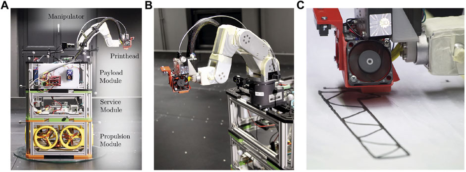
FIGURE 1. Setup of the modular free-flyer with propulsion, service and payload module (A) and a close-up view of the robotic arm (B) with print head in operation (C).
The pose controller enables closed-loop control of the base link and is decoupled from the control loop of the manipulator, which has an integrated controller. Three distinct proportional-integral-derivative (PID) controllers are used for position and attitude control (Figure 2). This control type was chosen as the system dynamics of the free-flyer approximately correspond to that of a first-order system for which PID control is well suited, as well as their simple methods for tuning. The controllers output a wrench
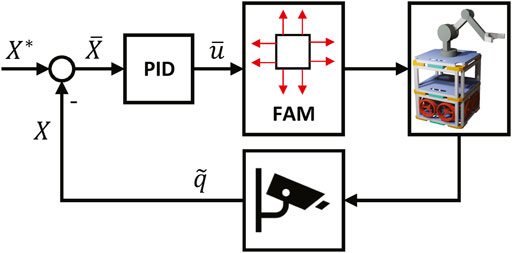
FIGURE 2. Block diagram showing the closed-loop controller used for position control. The desired position X* is compared with the feedback signal X to give the desired change in position
The required thruster forces can be determined by taking the pseudoinverse of M (denoted as M†) and scaling by a factor of 2. This scaling is required to make up for the fact that the thrusters are unidirectional (Zappulla et al., 2017).
The demanded force fi of each thruster is then mapped linearly to the demanded rpm of the thrusters and a pulse-width modulation (PWM) signal is generated accordingly causing the propellers to spin and accelerate the free-flyer. The free-flyer’s pose in the world frame
Unlike traditional layer-by-layer printing, where material is deposited on previously printed material, the method used in this paper is free-form printing, where material is extruded and cooled in 3 dimensional space. This has the benefit of enabling the manufacture of sparse structures, such as trusses, where material is orientated along the load path (Liu et al., 2018). As discussed in Section 1, one of the benefits of ISM is that structures would only need to withstand the relatively benign loads of microgravity, and this could be achieved using this manufacturing technique.
For terrestrial use, free-form printing has been explored as a way to reduce printing time for prototypes. In the Wireprint study (Mueller et al., 2014), it was necessary to pause the nozzle at the top of each upward stroke. This would keep the molten material under tension until it cooled sufficiently to become solid. The downward stroke could then be printed. If the material was not kept under tension, it would sag due to gravity, and the desired shape would not be formed. In microgravity, liquid can behave unpredictably. It is therefore also preferable to keep the molten material under tension. In this study, rather than pausing we keep the material permanently under tension by using an extrusion speed lower than the movement speed of the printhead, at 2.75 mm/s and 3.33 mm/s, respectively. This removes the need for pauses, but requires an additional custom command. It was also found that the nozzle geometry determines the maximum allowable height and geometry of free-form structures. For our setup, we are restricted to a height of 5.5 mm, and an angle of less than 45° with the horizontal; Figure 3 shows how increasing this height or angle will cause the printhead to recontact already printed material. This could be improved through the design of a longer, narrower nozzle, or by modifying the orientation of the printhead.
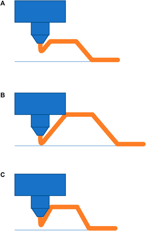
FIGURE 3. A schematic showing how the printhead geometry restricts free-form printing. In (A) the height and angles of the trapeze are compatible with the print head. In (B) the increased height causes the printhead to recontact already printed material. In (C) the steeper angle causes the nozzle to recontact already printed material.
The material used in this study is polylactic acid (PLA)6. To reduce the time required for the extruded material to solidify, a lower than recommended temperature of 180°C was used (Alsoufi et al., 2019). The diameter of the nozzle also affects the cooling time, with smaller diameters requiring less time. It was found that free-form printing was possible with diameters of 0.4, 0.8, and 1.2 mm. Due to the increased cooling time, larger diameters required lower printing speeds to be successful. Ultimately, a diameter of 1.2 mm was chosen as it produced structures with the required level of stiffness for depositing subsequent layers onto the already printed free-form structures without distorting them. To further improve the cooling time, two fans were trained on material exiting the nozzle. In the vacuum environment of space, cooling via convection is not possible, and would largely be dependent on the thermal radiation environment. A further study would be required to examine what cooling rates would be possible.
Structures were printed onto a stationary glass platform, coated in paper, which was itself coated in adhesive7. This combination resulted in good adhesion between the substrate and printed structures. This was critical to prevent the printed structure from moving during the printing process. As with conventional 3D printing, the algorithm used assumes that material remains where it was deposited. It was not capable of compensating for any movement of the printed structure.
As truss structures have been identified as one of the most promising structures for on-orbit manufacture, a design for a long free-form truss element was created. The truss element was split into a series of segments, each of which were printed as a continuous print path. Each segment fit in the robotic arm’s workspace, thereby enabling the manufacture objects larger than the setup itself. These segments were then printed whilst the free-flyer maintained a fixed position. Once each segment was completed, the free-flyer would move to a new position, and the next segment was manufactured. To ensure that a single structure was produced, the segments overlapped each other such that they were joined together.
Traditional FFF printing techniques have already been explored in microgravity, and with different orientations with respect to the gravity vector (Crocket et al., 1999; Snyder et al., 2013; Thomas et al., 2017). In general, it was found that it was possible to produce parts with a strength comparable to that of those printed in a conventional manner. Experiments have also been conducted to investigate the effects of varying the gravitational vector on free-form printing, and it was found that it is possible to manufacture structures in −1 g (Jonckers et al., 2021). It is therefore assumed that the technique should be possible in microgravity.
Like a spacecraft on-orbit, the free-flyer experiences external disturbances and must counteract these during operations. As described in Section 2, three separate PID controllers are used to control the x and y positions, and the orientation θ of the free-flyer. During the printing phase, the free-flyer is in station keeping mode, i.e., it should maintain a fixed position and orientation. These controllers must then negate the various disturbances which act on the free-flyer. The largest system disturbance, i.e., a disturbance caused by the system itself, is residual gravitational acceleration. This is due to the panels making up the air bearing table not being perfectly perpendicular to the gravity vector (Ivanov et al., 2018). Inclination measurements taken on the ELISSA table show that residual gravitation acceleration varies slowly across the table, as each panel has a maximum inclination variation of ± 0.05°/m. The magnitude of the acceleration can reach 9.6 mm/s2, whilst the direction varies. The movement of the robotic arm also generates a disturbance force, due to dynamic coupling, though due to slow movement speeds, and low mass of the robotic arm compared to the free-flyer, these forces are expected to be small (Rybus et al., 2019). Other disturbances due to aerodynamic forces and torques produced by the active air blowing system are measured to account for less than 10% of all residual accelerations achieving a friction coefficient of
Disturbances to which spacecraft on-orbit are subjected include, aerodynamic forces, solar radiation pressure and dynamic coupling, though these are smaller in magnitude than those experienced on the ELISSA table. For example, a typical 4,000 kg spacecraft in geostationary orbit experiences disturbance forces up to 50 mN along each axis, resulting in an acceleration of approximately 1.25 × 10⁻² mm/s2 (Weiss and Di Cairano, 2015). Spacecraft therefore also require control systems for station keeping.
In general, the PID controller copes well with slowly changing disturbances such as the residual gravitational acceleration. As illustrated in Figure 4, the control system is capable of maintaining a position with errors with a magnitude of approximately ± 2 mm in the x and y directions. It also maintains orientation about the z axis within ± 0.5° when not printing. As the printhead, or tool centre point (TCP), is located approximately 400 mm from the geometric centre of the free-flyer (illustrated in Figure 5), any rotational error results in further position error for the nozzle. Figure 4 shows the error of the printing nozzle incurred when the effects of the rotational and linear errors are summed. It can be seen that the error is up to 5.5 mm in the x direction. With a nozzle diameter of 1.2 mm, an error of this magnitude would prevent structures being printed. The robot arm can, however, be used to correct for this, by moving instead to the desired position in the world frame of reference. These printhead position errors are also possible for a spacecraft on-orbit, as it is unlikely that the printhead will be located at the spacecraft’s centre. It may, however, be preferable to correct this error using other means, such as reaction wheel or control moment gyroscopes.
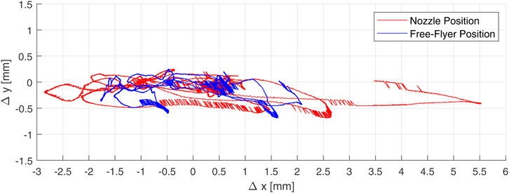
FIGURE 4. Plot showing the free-flyer (blue) and nozzle (red) deviation from their nominal positions whilst station keeping for 120 s.
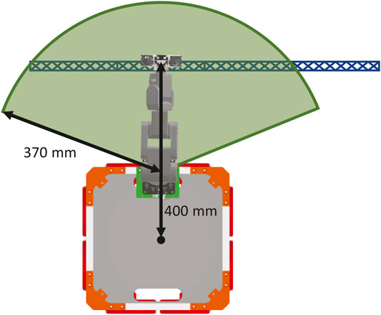
FIGURE 5. Diagram showing the workspace (the area shaded in green) of the robotic arm whilst printing a multi-segment truss. Individual segments fit within the workspace, and by moving the free-flyer and printing subsequent segments, it is possible to produce a structure larger than the workspace.
The position error illustrated in Figure 4 can be compensated for by commanding the robot to move to a position which corresponds to the desired nozzle position in the world frame. The error should be corrected for as frequently as possible to ensure that the printed structure resembles the design. The design of the printed structures consists of a series of points in 3D space. These are defined using G-Code, a language typically used to control 3D printers. The printhead moves in a straight line between these end points, and extrudes material. As the time between these G-Code commands can be tens of seconds long, the free-flyer’s position would vary whilst printing one of these lines, resulting in large errors. Intermediate points between the co-ordinates in the G-Code were therefore generated to produce a finer trajectory for the robotic arm to follow. The distance between these intermediate points is determined by the desired velocity of the end effector, as well as the period between which commands could be sent to the robotic arm, in our case 3.33 mm/s and 60 ms, respectively. As the Cartesian distance travelled for each G-Code command is not exactly divisible by the distance the robotic arm would travel during the nominal time step, the length of the final interval was extended to accommodate the whole distance. An example is illustrated in Figure 6. In this case, a line with a length of 0.9 mm is to be printed. With a TCP velocity of 3.33 mm/s, and a period between robot arm commands of 60 ms, the TCP moves approximately 0.2 mm between commands. Intermediate points along the line are therefore generated at this interval (denoted M1, M2, etc). The final intermediate point would, however, require an update period of 30 ms between it and the line end point. To ensure that the minimum period is not violated, the last intermediate point is eliminated, increasing the length of the final interval to 90 ms.
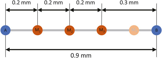
FIGURE 6. Diagram illustrating the generation of intermediate points (M1, M2, etc. In orange) between G-Code commands (A and B, in blue) to produce a trajectory for the robotic arm.
The command sent to the robot is in the form of desired transformation between the robot base reference frame and the TCP of the robot, with a linear velocity at which the end effector is to move. A diagram showing the location of each reference frame is given in Figure 7. The transformation portion of the command,
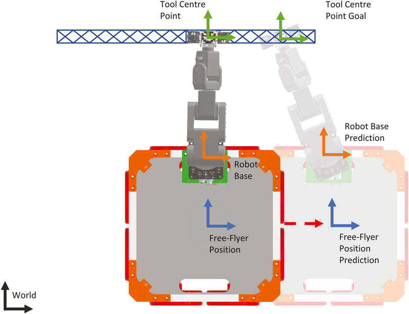
FIGURE 7. Diagram showing the reference frames used for the control of the free-flyer and robotic arm. The world frame is shown in black, the free-flyer reference frames are shown in blue, the robotic arm base frames are shown in orange, and the print and tool centre point frames are shown in green. The predicted free-flyer position is translucent. The distance between the current and predicted positions is exaggerated.
Where
Where
The velocity at which the robotic arm should move the end effector, is given by
where
It should be noted that the control scheme for both the free-flyer and the robotic arm are dependent upon having accurate position data in the world frame - in this case provided by the optical tracking system. For a spacecraft, it is likely that the position would be measured relative to the printed structure, and this may be less precise than the optical tracking data. As such, modifications to the control scheme would be necessary for on-orbit operation.
The feasibility of the proposed approach was verified by printing a repeatable, customised, free-form complex structure in single direction. It can be hypothesised that the ability to print consistently in one direction can be extended in all three in a standard free floating environment. Specifically, a 775 mm long truss element formed of 7 individually printed segments was manufactured. In addition to this, individual segments were printed to examine the improvement when error correction by the robotic arm is introduced.
To assess the performance of the error correction algorithm described in Section 4, a number of dry runs were performed, where the printhead was disabled, and the print platform removed. The free-flyer would then perform station keeping whilst the robotic arm was moved through the trajectory required to print a 110 mm truss element. This size was chosen as it could comfortably fit within the workspace of the robotic arm, thereby providing some margin for the correction of free-flyer pose errors. Figure 8A and Figure 8B show the recorded positions of the nozzle for a dry run without and with the error correction algorithm, respectively. It can be seen that in both cases the nozzle largely follows the desired path. Due to the orientation error of the free-flyer, it was expected that the errors would be larger in the X direction of the world frame than in the Y direction when the compensation algorithm was not applied. This was observed, with the mean error being over twice as large in the X direction than in the Y direction, with values of 0.68 and 0.28 mm respectively. This can be clearly seen in Figure 8A at the origin, where the measured trajectory is to the side of the desired trajectory.
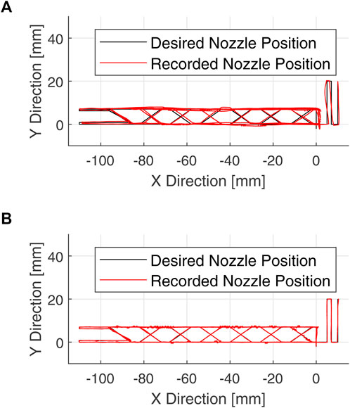
FIGURE 8. Plots of the TCP position (red) during dry runs, where the compensation algorithm was not used (A), and where the compensation algorithm was used (B). The desired position is shown in black.
Mean errors of 0.77 and 0.26 mm, were measured for the dry run without and with the compensation algorithm, respectively. The algorithm therefore resulted in approximately a 66% reduction in mean error. Though the mean error of the dry run without the compensation algorithm is less than the nozzle diameter, the maximum error measured 2.35 mm, is approximately twice as large. If the error were this large at a node of the truss, it would result in the join being missed. It is therefore expected that structures printed without compensation would be of poor quality. By contrast, the maximum error of the dry run with the compensation algorithm was 1.53 mm, only 35% less than without the algorithm. It is thought that the lower improvement compared to the mean error is due to sudden changes in the free-flyer pose, which the compensation algorithm struggles to correct for.
Next, these truss elements were printed onto the print substrate whilst the free-flyer maintained a fixed position. Figures 9A,B show the recorded position of the nozzle for printing without and with the correction algorithm, respectively. In this case, it can be seen that without the correction algorithm, the nozzle position deviates significantly from the desired trajectory, resulting in a trajectory which does not resemble the design. Quantified, a mean error of 8.42 mm was measured, representing approximately an 11-fold increase compared to the dry run. As such, no recognisable structure could be produced. This increase in error was observed to be caused by friction between the nozzle and the print substrate, or already printed material. Any applied force disturbs the position of the free-flyer, which then requires some time to counteract the disturbance. By contrast, the mean error with the correction algorithm only saw an increase of 4%, when compared to the dry run, to 0.27 mm. A truss structure could therefore be successfully printed, and is shown in Figure 10.
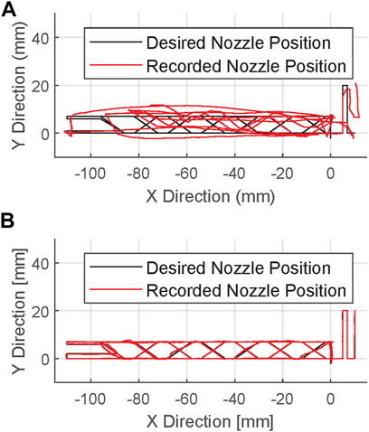
FIGURE 9. Plots of the TCP position (red) during prints of a truss segment, where the compensation algorithm was not used (A), and where the compensation algorithm was used (B). The desired position is shown in black.
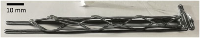
FIGURE 10. Photograph showing the truss structure which was printed using the error correction algorithm.
The impact of the disturbance caused by friction can also be seen in the maximum error, which was measured to be 55.45 mm without and 2.89 mm with the compensation algorithm. Though a marked improvement, the impact of the errors can be seen in Figure 10, where the joining of a node has failed on the left side. The point of maximum error was observed to occur at the same position for repeated experiments, and was caused by particularly high friction between the nozzle and already printed structure. In the future, it should be possible to modify the design of the structure being manufactured to reduce this friction, and to therefore reduce the error to the magnitudes observed during the dry run.
Having illustrated that the error correction algorithm allows the printing of structures with a degree of accuracy which allows some of the nodes of the truss to be joined, the capability to manufacture a structure larger than the robotic arm’s workspace was demonstrated. A design for a second truss element was created, such that it would overlap, and therefore join to a previously printed truss. This element could then be repeated to produce a truss of arbitrary length. A series of 7 segments were printed, each with the free-flyer maintaining a fixed position, together forming a truss with a total length of 775 mm, as shown in Figure 11.
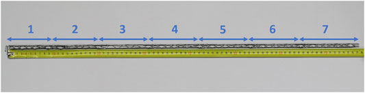
FIGURE 11. Photograph showing the long truss structure, produced by joining together 7 segments.
To join the individual segments together, they are overlapped, as shown in Figure 12. For this to be successful, material must be deposited onto the already printed structure. This is only achievable if the location of the previously printed material is known. In this case, it was assumed that the previous segment had been printed without errors, and the free-flyer was moved a known distance whilst the print platform remained stationary. For a spacecraft in orbit, these assumptions may not be valid, and it might be necessary to determine the position of the previously printed structure using another method, such as computer vision. This has already been achieved for other AM techniques (Kulkarni et al., 2020).
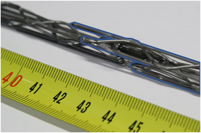
FIGURE 12. Photograph showing on of the overlaps between truss segments. The subsequently printed truss is highlighted in blue.
The compensation algorithm was found to reduce the impact of external disturbances on the nozzle accuracy. This was especially apparent during the printing process, where the algorithm reduced the mean and maximum errors during printing by 97 and 95%, respectively. However, even in the absence of friction caused by printing, maximum errors with the compensation algorithm were the same order of magnitude as the nozzle diameter.
For a spacecraft in orbit, the PID controller used for the free-flyer position could easily be extended to 6 DoF by adding new controllers for the Z axis, and rotation around the Y and X axes. The compensation algorithm already uses the full state off the free-flyer and TCP, and therefore would not require any modification. Whilst errors in the Z direction were negligible during the experiment, in a 6 DoF environment, it is expected they would be of a similar magnitude to those experienced in the X and Y directions. As this could result in the reduction of the layer height, it could also result in a higher friction force, thereby resulting in yet larger errors. It is therefore recommended that for AM in space, a more robust control approach is used for the robotic arm, and the spacecraft. Furthermore, in the case where the spacecraft is printing onto another spacecraft, the two could be docked together, thereby eliminating any relative motion. However, for a long structure, this would either require multiple docking mechanisms - representing increased mass and complexity; or a docking approach which does not require the use of a complex mechanism (Trentlage et al., 2016; Ben Larbi et al., 2017).
Furthermore, a series of truss segments were printed such that they joined together, successfully forming a structure with a size larger than the workspace of the robotic arm. The mechanical strength of this truss is impacted by the joints between individual segments. A typical 3D printer joins each layer to the previous layer by extruding at a height less than half the nozzle diameter. This applies a force, and heats up the previous layer, ensuring a strong bond. On the air bearing table however, it was found that extruding at a height less than half the nozzle diameter greatly increased friction between the nozzle and the print substrate, to the extent that the free-flyer would struggle to move, thereby resulting in large deviations from the desired trajectory. Furthermore, for a spacecraft in a 6 DoF free-floating environment, to apply this force, a constant reaction force would need to be applied by the spacecraft’s thrusters - increasing fuel consumption. A layer height of 0.8 mm, or 75% of the nozzle diameter was therefore used. Additionally, a lower than recommended printing temperature was used (Section 3). These two factors resulted in weak bonding at these joints. It would therefore be desirable to use a joining method which does not require applying a force, for example, preheating the previous material using a non-contact method such as a laser.
Though the demonstration in this paper was limited to one type of structure with theoretically limitless length, by utilising the segmentation approach, it would be possible to produce structures with unlimited size in 2 or 3 dimensions (though it would not be possible to test the latter on the air bearing table). This would require an algorithm to split such structures into printable segments, as well as path planning to ensure that the free-flying spacecraft does not contact previously printed parts of the structure. This segmentation approach should take the workspace of the robotic arm into account, to reduce the total number of segments required. It should also ensure that the fuel required is kept as low as possible, as this is a limited resource for spacecraft. Different control approaches could also be explored, to examine their impact on fuel consumption. For example, allowing the free-flyer to drift further from the nominal position, may reduce fuel consumption, so long as the robotic arm can still correct for this larger error. The power consumption of the robotic arm should also be monitored, though it should be noted that the current approach utilises a single print path for each segment, meaning a more efficient print path is not possible. More efficient designs may, however, be possible. Future experiments will examine how structures which are large in 2 dimensions can efficiently be split into printable segment sections, and how the path planning for such a structure impacts energy consumption.
The material printed in these experiments was PLA, this was chosen for this demonstration due to its ease of printing, low cost and low printing temperature (and therefore corresponding low power requirements). However, it is unlikely that this material would be suitable for in space manufacturing. It is therefore recommended that other materials are investigated for their suitability, both for space environment, and for their compatibility with the described manufacturing technique. The use of engineering thermoplastics such as PEEK, PEKK (Polyetherketoneketone) and Ultem have been investigated for spacecraft components, and are possible to manufacture with current FFF technology (Kafi et al., 2020; Kaplun et al., 2020; Rinaldi et al., 2020). Additionally, investigations have shown that material properties can be further improved by combining continuous fibre-reinforcement with the FFF process (Tian et al., 2016; Pappas et al., 2021). Furthermore, research has shown that it is possible to print bulk metallic glasses to produce metallic parts using FFF (Gibson et al., 2018). Bringing together these technologies with our proposed concept would enable the manufacture of high strength structures for in-orbit applications, though it would require some adaption to the approach taken. For example, engineering thermoplastics have higher printing temperatures than PLA, (Rinaldi et al., 2020), for instance printed PEEK at 410°C, whilst we printed PLA at 180°C. It would be expected that the cooling rate would be greater at higher temperatures, however, PEEK would have to lose more heat before solidifying. As such, the printing parameters, the truss design, or both, may need to be modified to successfully repeat the experiments with other materials.
Ultimately, the work carried out in this paper is only the first step towards realising AM for ISM. Many other aspects should be investigated to determine if it is truly viable, some of which some of which would only be possible to test on-orbit. These include, but are not limited to:
• Position accuracy of actual spacecraft hardware (both the robotic arm, and the spacecraft)
• Energy-efficient control of free-flyer and robotic arm
• Material and process compatibility with the space environment
• Economic factors such as the material and hardware costs when compared to traditional deployment methods
In this paper, we investigated the concept of using a free-flying spacecraft equipped with a robotic manipulator and AM end effector to manufacture large structures. Experiments were performed using a fan propelled robot on an air bearing table, thereby simulating the frictionless environment of microgravity. An algorithm was developed to ensure that the robotic arm position accuracy was sufficient to allow the manufacture of free-form truss elements. It was shown that it is possible to manufacture a single truss element, which could fit into the workspace of the robotic arm, with a mean error of 0.27 mm. Finally, the capability to manufacture a structure larger than the workspace of the robotic arm was shown by joining together 7 truss segments into a 775 mm long truss. The length of this truss could have been arbitrarily extended by adding further segments. Furthermore, this could be further developed to produce structures with unlimited size in all three dimensions in 3D space. Avenues to develop the process further to produce structurally useful parts were also discussed.
The raw data supporting the conclusion of this article will be made available by the authors, without undue reservation.
DJ: Conceptualisation, Methodology, Software, Validation, Formal analysis, Investigation, Writing—Original Draft, Writing—Review and Editing, Visualisation. OT: Conceptualisation, Methodology, Software, Validation, Formal analysis, Investigation, Writing—Original Draft, Visualisation. AT: Conceptualisation, Supervision, Writing—Review and Editing. LM: Software, Writing—Original Draft.
We acknowledge support by the Open Access Publication Funds of Technische Universität Braunschweig.
The authors declare that the research was conducted in the absence of any commercial or financial relationships that could be construed as a potential conflict of interest.
All claims expressed in this article are solely those of the authors and do not necessarily represent those of their affiliated organizations, or those of the publisher, the editors and the reviewers. Any product that may be evaluated in this article, or claim that may be made by its manufacturer, is not guaranteed or endorsed by the publisher.
AM, Additive Manufacturing; DoF, Degrees of Freedom; ELISSA, Experimental Lab for Proximity Operations and Space Situational Awareness; FFF, Fused Filament Fabrication; GNC, Guidance, Naviation and Control; ISM, In Space Manufacturing; PEEK, Polyether Ether Ketone; PEKK, Polyetherketoneketone; PID, Proportional-Integral-Derivative (Controller); PLA, Polylactic Acid; PWM, Pulse-Width Modulation; ROS, Robot Operating System; TCP, Tool Centre Point.
1OptiTrack, OptiTrack, USA
2SmartNozzle™, CoreFlow Ltd., Israel
3NVIDIA Jetson TX2, NVIDIA Corporation, USA
4Meca500, Mecadmic Robotics, Canada
5Arduino Mega, Arduino S.r.l., Italy
6Anthrazit V2, Das Filament, Germany
7UHU Stic, UHU, Germany
Alsoufi, M. S., Alhazmi, M. W., Suker, D. K., Alghamdi, T. A., Sabbagh, R. A., Felemban, M. A., et al. (2019). Experimental Characterization of the Influence of Nozzle Temperature in Fdm 3d Printed Pure Pla and Advanced Pla+. Am. J. Mech. Eng. 7, 45–60. doi:10.12691/ajme-7-2-1
Belvin, W. K., Doggett, W. R., Watson, J. J., Dorsey, J. T., Warren, J. E., Jones, T. C., et al. (2016). “In-space Structural Assembly: Applications and Technology,” in 3rd AIAA Spacecraft Structures Conference (Reston, Virginia: American Institute of Aeronautics and Astronautics). AIAA SciTech Forum. doi:10.2514/6.2016-2163
Ben Larbi, M. K., Grzesik, B., Radtke, J., and Stoll, E. (2017). “Active Debris Removal for Mega Constellations: Cubesat Possible?,” in 9th International Workshop on Satellite Constellations and Formation Flying (Boulder, United States: International Astronautical Federation).
Ben-Larbi, M., Grzesik, C., Trentlage, B., Yang, J., Höfner, C., and Stoll, E. (2016). “Algorithm and Technology Development for Active Debris Removal at the institute of Space Systems,” in Deutscher Luft- und Raumfahrtkongress (Braunschweig, Germany: Deutsche Gesellschaft für Luft- und Raumfahrt).
Brinkmann, W., Jankovic, M. V., Gancet, J., Letier, P., Kreisel, J., Schervan, T. A., et al. (2021). “Preliminary Definition of a Standard Interconnect Benchmark for on- Orbit Servicing Demonstrator,” in Stardust-R – Second Global Virtual Workshop. (Virtual): STARDUST-R
Crocket, R., Peterson, D., and Cooper, K. (1999). “Fused Deposition Modelling in Microgravity,” in 1999 Solid Freeform Fabrication Symposium Proceedings (Austin, Texas: University of Texas at Austin), 671–678.
Doggett, W. (2002). “Robotic Assembly of Truss Structures for Space Systems and Future Research Plans,” in Proceedings, IEEE Aerospace Conference (Big Sky, United States: IEEE), 7–3589–7–3598. doi:10.1109/aero.2002.1035335
Dunn, J. J., Hutchison, D. N., Kemmer, A. M., Ellsworth, A. Z., Snyder, M., White, W. B., et al. (2010). 3D Printing in Space: Enabling New Markets and Accelerating the Growth of Orbital Infrastructure. Mountain View, United States: Space Studies Institute.
Eun, Y., Park, S.-Y., and Kim, G.-N. (2018). Development of a Hardware-In-The-Loop Testbed to Demonstrate Multiple Spacecraft Operations in Proximity. Acta Astronautica 147, 48–58. doi:10.1016/j.actaastro.2018.03.030
Everett, M., Flores-Abad, A., Khan, A., Masum Billah, K., Herzog, E., Rahman, A., et al. (2018). “A 1u Cube-Satellite for Electrically Conductive 3d Printing in Gto,” in 2018 AIAA SPACE and Astronautics Forum and Exposition (Reston, Virginia: American Institute of Aeronautics and Astronautics). doi:10.2514/6.2018-5231
French, K. (2021). “Advanced Technologies: 7 Degrees of freedom Robotic Arm on Archinaut One,” in Proceedings of the Small Satellite Conference. (Virtual): Utah State University.
Gibson, M. A., Mykulowycz, N. M., Shim, J., Fontana, R., Schmitt, P., Roberts, A., et al. (2018). 3d Printing Metals like Thermoplastics: Fused Filament Fabrication of Metallic Glasses. Mater. Today 21, 697–702. doi:10.1016/j.mattod.2018.07.001
Hoyt, R., Cushing, J., Jimmerson, G., Slostad, J., Dyer, R., and Alvarado, S. (2016). SpiderFabTM: Process for On-Orbit Construction of Kilometer-Scale Apertures. Greenbelt, United States: Tethers Unlimited Inc. Tech. rep..
Ivanov, D., Koptev, M., Mashtakov, Y., Ovchinnikov, M., Proshunin, N., Tkachev, S., et al. (2018). Determination of Disturbances Acting on Small Satellite Mock-Up on Air Bearing Table. Acta Astronautica 142, 265–276. doi:10.1016/j.actaastro.2017.11.010
Jonckers, D., Tauscher, O., Stoll, E., and Thakur, A. (2021). “Feasibility Study of Large-Format, Freeform 3d Printing for On-Orbit Additive Manufacturing,” in 2021 Solid Freeform Fabrication Symposium Proceedings (Austin, United States: University of Texas at Austin), 1508–1526. doi:10.26153/tsw/17663
Kafi, A., Wu, H., Langston, J., Atak, O., Kim, H., Kim, S., et al. (2020). Evaluation of Additively Manufactured Ultraperformance Polymers to Use as thermal protection Systems for Spacecraft. J. Appl. Polym. Sci. 137, 49117. doi:10.1002/app.49117
Kaplun, B. W., Zhou, R., Jones, K. W., Dunn, M. L., and Yakacki, C. M. (2020). Influence of Orientation on Mechanical Properties for High-Performance Fused Filament Fabricated Ultem 9085 and Electro-Statically Dissipative Polyetherketoneketone. Additive Manufacturing 36, 101527. doi:10.1016/j.addma.2020.101527
Kolvenbach, H., and Wormnes, K. (2016). “Recent Developments on ORBIT, a 3-DOF Free Floating Contact Dynamics Testbed,” in 13th International Symposium on Artificial Intelligence, Robotics and Automation in Space (I-SAIRAS 2016). Beijing, China: China National Space Administration
Kugler, J., Cherston, J., Joyce, E. R., Shestople, P., and Snyder, M. P. (2017). “Applications for the Archinaut in Space Manufacturing and Assembly Capability,” in AIAA Space and Astronautics Forum and Exposition 2017 (Red Hook, NY: Curran Associates Inc). doi:10.2514/6.2017-5365
Kulkarni, P., Magikar, A., and Pendse, T. (2020). “A Practical Approach to Camera Calibration for Part Alignment for Hybrid Additive Manufacturing Using Computer Vision,” in Intelligent Manufacturing and Energy Sustainability. Editors A. Reddy, D. Marla, M. Simic, M. N. Favorskaya, and S. C. Satapathy (Singapore: Springer Singapore), 221–229. vol. 169 of Smart Innovation, Systems and Technologies. doi:10.1007/978-981-15-1616-0_21
LeMaster, E., Schaechter, D., and Carrington, C. (2006). “Experimental Demonstration of Technologies for Autonomous On-Orbit Robotic Assembly,” in Space 2006 (San Jose, California: American Institute of Aeronautics and Astronautics). doi:10.2514/6.2006-7428
Levedahl, B., Hoyt, R. P., Silagy, T., Gorges, J., Britton, N., and Slostad, J. (2018). “Trusselator Technology for In-Situ Fabrication of Solar Array Support Structures,” in AIAA Spacecraft Structures Conference 2018 (Red Hook, NY: Curran Associates Inc). doi:10.2514/6.2018-2203
Li, J., Aubin-Fournier, P.-L., and Skonieczny, K. (2021). Slaam: Simultaneous Localization and Additive Manufacturing. IEEE Trans. Robot. 37, 334–349. doi:10.1109/TRO.2020.3021241
Liu, S., Li, Y., and Li, N. (2018). A Novel Free-Hanging 3d Printing Method for Continuous Carbon Fiber Reinforced Thermoplastic Lattice Truss Core Structures. Mater. Des. 137, 235–244. doi:10.1016/j.matdes.2017.10.007
McCrea, J., Cerri, J. T., and Hartsfield, C. R. (2018). “Design of a Zero-Gravity, Vacuum-Based 3d Printer Robot for Use of In-Space Satellite Assembly,” in 2018 AIAA Aerospace Sciences Meeting (Reston, Virginia: American Institute of Aeronautics and Astronautics). AIAA SciTech Forum. doi:10.2514/6.2018-2201
Moraguez, M., and de Weck, O. (2020). “Benefits of In-Space Manufacturing Technology Development for Human Spaceflight,” in 2020 IEEE Aerospace Conference (Piscataway, NJ: IEEE), 1–11. doi:10.1109/AERO47225.2020.9172304
Mueller, S., Im, S., Gurevich, S., Teibrich, A., Pfisterer, L., Guimbretière, F., et al. (2014). “Wireprint,” in Proceedings of the 27th Annual ACM Symposium on User Interface Software and Technology. Editors H. Benko, M. Dontcheva, and D. Wigdor (New York, NY, USA: ACM), 273–280. doi:10.1145/2642918.2647359
O'Connor, H. J., and Dowling, D. P. (2019). Low‐pressure Additive Manufacturing of Continuous Fiber‐reinforced Polymer Composites. Polym. Composites 40, 4329–4339. doi:10.1002/pc.25294
Pappas, J. M., Thakur, A. R., Leu, M. C., and Dong, X. (2021). A Parametric Study and Characterization of Additively Manufactured Continuous Carbon Fiber Reinforced Composites for High-Speed 3d Printing. Int. J. Adv. Manuf Technol. 113, 2137–2151. doi:10.1007/s00170-021-06723-1
Quintana, J., Pérez, P., Flores-Abad, A., Chessa, J., and Choudhuri, A. (2019). “Orbital Factory 2: A 1u Cubesat for Additive Manufacturing Tasks in Low Earth Orbit,” in Proceedings of the Small Satellite Conference. Logan, United States: Utah State University
Rinaldi, M., Cecchini, F., Pigliaru, L., Ghidini, T., Lumaca, F., and Nanni, F. (2020). Additive Manufacturing of Polyether Ether Ketone (Peek) for Space Applications: A Nanosat Polymeric Structure. Polymers 13, 11. doi:10.3390/polym13010011
Rybus, T., Seweryn, K., Oleś, J., Basmadji, F. L., Tarenko, K., Moczydłowski, R., et al. (2019). Application of a Planar Air-Bearing Microgravity Simulator for Demonstration of Operations Required for an Orbital Capture with a Manipulator. Acta Astronautica 155, 211–229. doi:10.1016/j.actaastro.2018.12.004
Sacco, E., and Moon, S. K. (2019). Additive Manufacturing for Space: Status and Promises. Int. J. Adv. Manufacturing Techn. 105, 4123–4146. doi:10.1007/s00170-019-03786-z
Saulnier, K., Pérez, D., Huang, R., Gallardo, D., Tilton, G., and Bevilacqua, R. (2014). A Six-Degree-Of-freedom Hardware-In-The-Loop Simulator for Small Spacecraft. Acta Astronautica 105, 444–462. doi:10.1016/j.actaastro.2014.10.027
Snyder, M., Dunn, J., and Gonzalez, E. (2013). “The Effects of Microgravity on Extrusion Based Additive Manufacturing,” in AIAA SPACE 2013 Conference and Exposition (Reston, Virginia: American Institute of Aeronautics and Astronautics). doi:10.2514/6.2013-5439
Thomas, D., Snyder, M. P., Napoli, M., Joyce, E. R., Shestople, P., and Letcher, T. (2017). “Effect of Acrylonitrile Butadiene Styrene Melt Extrusion Additive Manufacturing on Mechanical Performance in Reduced Gravity,” in AIAA SPACE and Astronautics Forum and Exposition (Reston, Virginia: American Institute of Aeronautics and Astronautics). doi:10.2514/6.2017-5278
Tian, X., Liu, T., Yang, C., Wang, Q., and Li, D. (2016). Interface and Performance of 3d Printed Continuous Carbon Fiber Reinforced Pla Composites. Composites A: Appl. Sci. Manufacturing 88, 198–205. doi:10.1016/j.compositesa.2016.05.032
Trentlage, C., Mindermann, P., Ben Larbi, M. K., and Stoll, E. (2016). “Development and Test of an Adaptable Docking Mechanism Based on Mushroom-Shaped Adhesive Microstructures,” in AIAA SPACE 2016 (Reston, Virginia: American Institute of Aeronautics and Astronautics). doi:10.2514/6.2016-5486
Trentlage, C., Yang, J., Ben-Larbi, M., de Alba Padilla, C., and Stoll, E. (2018). “The ELISSA Laboratory: Free-Floating Satellites for Space-Related Research,” in Deutscher Luft- und Raumfahrtkongress (Friedrichshafen, Germany: Deutsche Gesellschaft für Luft- und Raumfahrt)
Tsiotras, P. (2014). Astros: A 5DOF Experimental Facility for Research in Space Proximity Operations. Adv. Astronautical Sci. 151, 717–730.
Weiss, A., and Di Cairano, S. (2015). “Opportunities and Potential of Model Predictive Control for Low-Thrust Spacecraft Station-Keeping and Momentum-Management,” in 2015 European Control Conference (ECC) (Linz, Austria: IEEE), 1370–1375. doi:10.1109/ecc.2015.7330729
Wilde, M., Clark, C., and Romano, M. (2019). Historical Survey of Kinematic and Dynamic Spacecraft Simulators for Laboratory Experimentation of On-Orbit Proximity Maneuvers. Prog. Aerospace Sci. 110, 100552. doi:10.1016/j.paerosci.2019.100552
Xue, Z., Liu, J., Wu, C., and Tong, Y. (2020). Review of In-Space Assembly Technologies. Chin. J. Aeronautics 34, 21–47. doi:10.1016/j.cja.2020.09.043
Yang, J., Khedar, Y., Ben-Larbi, M. K., Backhaus, J., Lampert, A., Bestmann, U., et al. (2021). Concept and Feasibility Evaluation of Distributed Sensor-Based Measurement Systems Using Formation Flying Multicopters. Atmosphere 12, 874. doi:10.3390/atmos12070874
Keywords: additive manufacturing, microgravity (μg), large scale 3D printing, robotic 3D printing, freeform 3D printing, in space manufacturing
Citation: Jonckers D, Tauscher O, Thakur AR and Maywald L (2022) Additive Manufacturing of Large Structures Using Free-Flying Satellites. Front. Space Technol. 3:879542. doi: 10.3389/frspt.2022.879542
Received: 19 February 2022; Accepted: 21 March 2022;
Published: 14 April 2022.
Edited by:
Angel Flores Abad, The University of Texas at El Paso, United StatesReviewed by:
Joseph N. Pelton, International Space University, United StatesCopyright © 2022 Jonckers, Tauscher, Thakur and Maywald. This is an open-access article distributed under the terms of the Creative Commons Attribution License (CC BY). The use, distribution or reproduction in other forums is permitted, provided the original author(s) and the copyright owner(s) are credited and that the original publication in this journal is cited, in accordance with accepted academic practice. No use, distribution or reproduction is permitted which does not comply with these terms.
*Correspondence: Aditya R. Thakur, YWRpdHlhLnRoYWt1ckB0dS1icmF1bnNjaHdlaWcuZGU=
†These authors have contributed equally to this work
Disclaimer: All claims expressed in this article are solely those of the authors and do not necessarily represent those of their affiliated organizations, or those of the publisher, the editors and the reviewers. Any product that may be evaluated in this article or claim that may be made by its manufacturer is not guaranteed or endorsed by the publisher.
Research integrity at Frontiers
Learn more about the work of our research integrity team to safeguard the quality of each article we publish.