 Toshiya Hanada
 Koki Fujita
 Yasuhiro Yoshimura
- 1Department of Aeronautics and Astronautics, Faculty of Engineering, Kyushu University, Fukuoka, Japan
- 2Department of Aerospace Engineering, School of Engineering, Nippon Bunri University, Oita, Japan
This paper briefly introduces a new approach to estimate some orbital parameters of on-orbit satellite fragmentations (specifically, the direction of angular momentum at a specific time and the time change in direction of angular momentum) from in-situ debris measurements. This approach, as in previous studies, adopts a constraint equation derived from the fact that a piece of debris detected shares the geocentric position vector with an in-situ debris measurement satellite. However, unlike previous studies, this approach does not adopt a constraint equation that can be applied to the rate of change in right ascension of the ascending node of a broken-up object. Instead, this approach determines the inclination of a broken-up object from the maximum or minimum geocentric declination at the time of detection. Then, this approach finds out a candidate for the rate of change in right ascension of the ascending node of a broken-up object by assuming a circular orbit with a radius of the geocentric distance at the time of detection. Finally, using the constraint equation adopted, this approach estimates the right ascension of the ascending node at the time of breakup and calculates a correction for the rate of change in right ascension of the ascending node. This paper also verifies that this new approach works effectively under ideal conditions where all detections are assumed to be at the line of intersection of the two orbital planes of a broken-up object and an in-situ debris measurement satellite.
1 Introduction
This study aims at an environmental estimation for tiny debris in the low Earth orbit (LEO). Whereas space debris larger than 10 cm in size are currently tracked from the ground and their orbital information is maintained and updated in some databases, those under 10 cm are not, mainly because of their low traceability. As seen in a verification experiment followed by the incident of ADEOS-II spacecraft of the Japan Aerospace Exploration Agency (JAXA), sub-millimeter-size debris can damage components of a spacecraft such as an electrical wiring harness. Therefore, building a collision flux model of sub-millimeter-size debris is urgent to mitigate the risk of their collision with spacecraft in operation.
There are two main approaches to measure an environment of sub-millimeter-size debris in LEO, that is, “ground-based” and “space-based” approaches. The former has been conducted by radar observations (Goldstein et al., 1998; Matney et al., 1999; Stokely et al., 2009). They are currently available to debris’ size limited to approximately 2 mm. On the other hand, as an example of the latter approach, in-situ debris measurement missions using debris impact sensors mounted on spacecraft body surfaces have been proposed (Ae et al., 2013; Hanada, 2013; Kitazawa et al., 2013; Bauer et al., 2014; Bauer et al., 2015; Anz-Meador et al., 2019; Oikonomidou et al., 2021) to detect micro-debris down to sub-millimeter in size.
Another advantage of those impact sensors for the in-situ debris measurement missions is that they can estimate a sub-millimeter-size debris environment more promptly than the other methods. For example, Kyushu University pursued a project for an In-situ Debris Environmental Awareness called “IDEA,” which aims at a prompt estimation of sub-millimeter-size debris environment utilizing small measurement satellites (Ae et al., 2013; Hanada, 2013). The final goal of the IDEA mission was to identify the position of on-orbit satellite fragmentations, which may generate a myriad of fragments. Whereas in conventional in-situ debris measurement approaches (McDonell et al., 1993; Aceti and Drolshagen., 1995), debris impact data on the retrieved spacecraft (or devices) have mainly time-integrated information, the proposed mission was expected to conduct a real-time measurement, that contributes to estimating a more exact orbital environment of space debris.
This study proposes a new approach to estimating some orbital parameters of on-orbit satellite fragmentations from in-situ debris measurements. Specifically, orbital elements herein indicate the direction of angular momentum at a specific time, that is, the right ascension of the ascending node (RAAN) and the inclination.
In the previous studies (Doi, 2013; Fujita et al., 2016; Furumoto et al., 2017; Kodama et al., 2019), based on a constraint equation of orbital conditions on both debris from specific on-orbit satellite fragmentations and a measurement satellite, some estimation techniques were applied for those unknown orbital parameters including in the constraint equation. Despite many refinements of the techniques applicable to actual locations of debris impact, the previously proposed methods are hard to solve the problem of converging into local minima because of the non-linear property seen in the constraint equation.
In this study, a fundamentally different approach is applied to avoid such a local minima problem. Instead of directly estimating unknown parameters of the constraint equation, the new approach firstly estimates one of the unknown orbital parameters, the inclination, by utilizing the timing that its amount coincides with the geocentric declination at the time of detection. Since the timing occurs when the geocentric declination has a maximum or minimum value, which should periodically appear during the orbital motion of measurement satellite and fragments from a specific on-orbit satellite fragmentation, we can estimate it from actual time-series observation data.
Once the inclination of the satellite fragmentation is estimated, the rate of change in RAAN can be subsequently estimated by utilizing a relationship between the two parameters implying an effect of
The following sections describe the above new approach in detail, as well as the constraint equation, which strongly affects the orbital parameters for both the fragmentation debris and the measurement satellite.
2 Constraint Equation
Ae et al. (2013) have investigated the nature of orbits on which debris may contribute to the collision flux to an in-situ debris measurement satellite. For this investigation, they applied an apogee-perigee filter to known objects in the catalog to eliminate objects which never approach the measurement satellite. Then, they evaluated the collision flux into the measurement satellite due to the objects not being eliminated by the apogee-perigee filter based on a spherical finite element model. Finally, they picked up contributors to the collision flux.
Furumoto et al. (2015) and Furumoto et al. (2017) have derived a constraint equation that can be applied to the contributors picked up by Ae et al. (2013). When an in-situ debris measurement satellite detects a piece of debris, the measurement satellite and the piece of debris share the geocentric position vector at the time of detection (see Figure 1). The angular momentum vector of the piece of debris should be perpendicular to the geocentric position vector at the time of detection. Therefore, it is possible to derive a constraint equation that can be applied to the orbital plane where the piece of debris was. Letting the geocentric position vector be
Note that
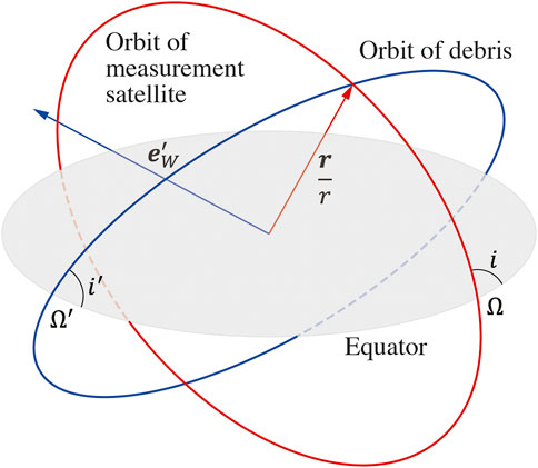
FIGURE 1. Relative orientation of orbital planes. A piece of debris detected shares the geocentric position vector with an in-situ debris measurement satellite.
Tasaki et al. (2014), Fujita et al. (2016), and Kodama et al. (2019) adopted this constraint equation to estimate some orbital parameters of a broken-up object from in-situ debris measurements. Since objects in LEO experience nodal precession or regression mainly due to
where
Where
In this study, the above constraint equation derived by Kodama et al. (2019), which can be applied to the rate of change in RAAN, is not utilized, but only the constraint equation given by Eq. 3 is utilized.
3 New Approach
Fujita et al. (2016) and Kodama et al. (2019) have demonstrated the importance of finding out a better candidate for the rate of change in RAAN of a broken-up object when they have verified their approaches theoretically. Especially, Kodama et al. (2019) have derived a constraint equation that can be applied to the rate of change in RAAN of a broken-up object. Instead, this study determines the inclination of a broken-up object from the maximum or minimum geocentric declination at the time of detection. Then, this approach finds out a candidate for the rate of change in RAAN of a broken-up object by assuming a circular orbit with a radius of the geocentric distance at the time of detection.
Let’s imagine an oblique spherical triangle on the celestial sphere with the orbits of an in-situ debris measurement satellite and a piece of debris detected, as illustrated in Figure 2. As in the previous section, variables with prime indicate those of a piece of debris detected. Therefore, variables without prime indicate those of an in-situ debris measurement satellite. For example,
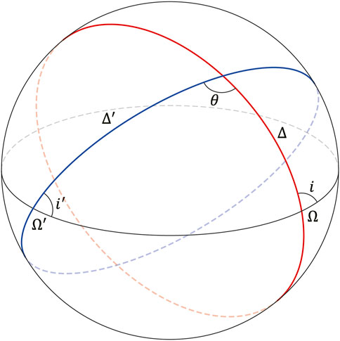
FIGURE 2. Relative orientation of orbital planes. An orbit in red represents the orbit of a measurement satellite, while the other orbit in blue represents the orbit of a piece of debris detected at the line of intersection.
From the sine formula, we obtain
where
From analog to the cosine formula for angles, we obtain
Therefore,
Multiplying Eq. 7 by
Finally,
Since the geocentric declination at the line of intersection of the two orbital planes can be expressed as
Subtracting Eq. 11 multiplied by
Except for special conditions such as
because the inclinations (
The geocentric declination at the line of intersection can also be expressed as
The secular variation of RAAN due to
where
4 Verification
Doi (2013) has demonstrated the time-averaged flux per unit area per day of fragments down to 100 μm from the Chinese anti-satellite missile test using Fengyun 1C in early January 2007 to a satellite in a Sun-synchronous orbit as a function of geocentric right ascension and declination. He observed that the time-averaged flux of fragments from the test into the satellite has two peaks along the orbit of the satellite. The two peaks are exactly located at the line of intersection of the two orbital planes of the satellite and the broken-up object. Therefore, this study assumes that an in-situ debris measurement satellite may detect a piece of debris from a broken-up object at the line of intersection of the two orbital planes.
Let’s assume that an in-situ debris measurement satellite in Table 1 detects fragments from a broken-up object also in Table 1 every 5 days, with a total of 74 in 1 year. It is also assumed that all detections are at the line of intersection of the two orbital planes. Figure 3 provides the history of geocentric declination at the time of detection. It looks like two waves with different phases are plotted together. This is because there are two points along the line of intersection, where the two orbital paths are close to each other. For this study, however, it is assumed that detections are only at a point with a closer distance between the two orbital paths along the line of intersection. Note that an orbit propagator used for this study considers not only
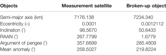
TABLE 1. Orbital parameters at the time of breakup.
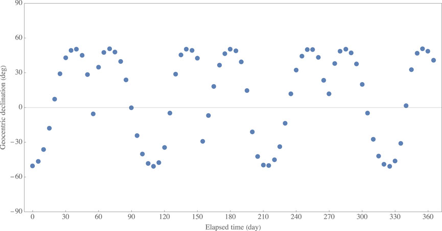
FIGURE 3. History of geocentric declination at the time of detection.
4.1 Inclination
The argument of true latitude corresponding to a given geocentric declination can be calculated by using
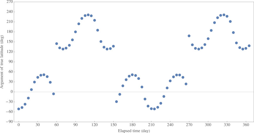
FIGURE 4. History of argument of true latitude corresponding to geocentric declination at the time of detection in Figure 3.
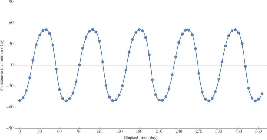
FIGURE 5. History of geocentric declination at the time of detection after reversing the sign of geocentric declination, where the corresponding argument of true latitude is between 90 and 270°. A solid line represents a fitted nonlinear model (periodic curve).
4.2 Rate of Change in Right Ascension of the Ascending Node
As described in Section 3, the rate of change in RAAN can be obtained from Eq. 12 by assuming a circular orbit with a radius of the geocentric distance at the time of detection. Applying this assumption to all data, then we can obtain candidates for the rate of change in RAAN, as shown in Figure 6. Since we do not know which candidate is better, this study adopts the mean of the candidates (i.e., −4.1755° per day as shown by a thick solid line) as a final candidate.
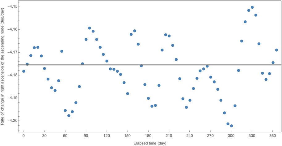
FIGURE 6. History of the rate of change in RAAN at the time of detection. A thick solid line represents the mean of the candidates.
4.3 Right Ascension of the Ascending Node
With the inclination estimated in Section 4.1 and the final candidate for the rate of change in RAAN obtained in Section 4.2, the RAAN at the time of breakup can be found as a root of the constraint equation derived in Section 2 (i.e., Eq. 3). Figure 7 shows a set of 74 constraints on
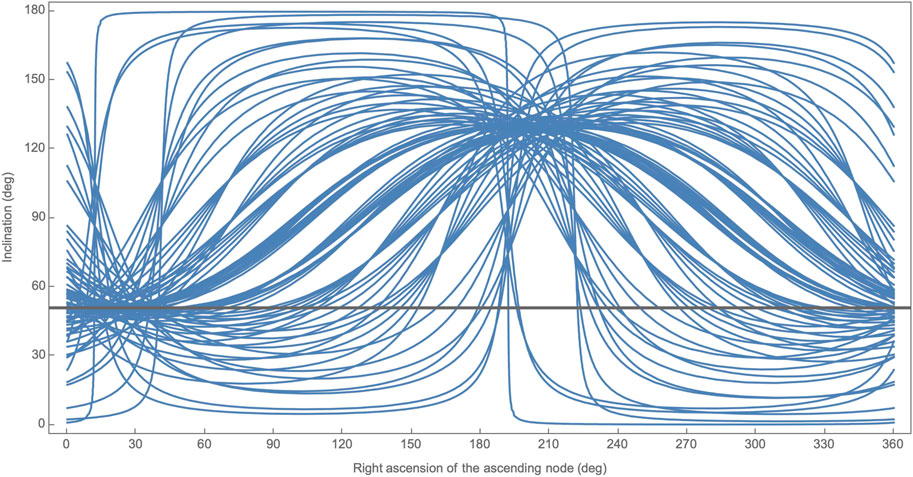
FIGURE 7. A set of 74 constrains on
Root-finding is made by applying the constraint equation to all data. Since the candidate for the rate of change in RAAN may include an error due to assumptions made in Section 4.2, the roots found are linearly time-dependent, as demonstrated in Figure 8. Some roots are out of the trend because of some difficulties with root-finding, but most roots change linearly over time. Figure 8 also shows a fitted linear model given by
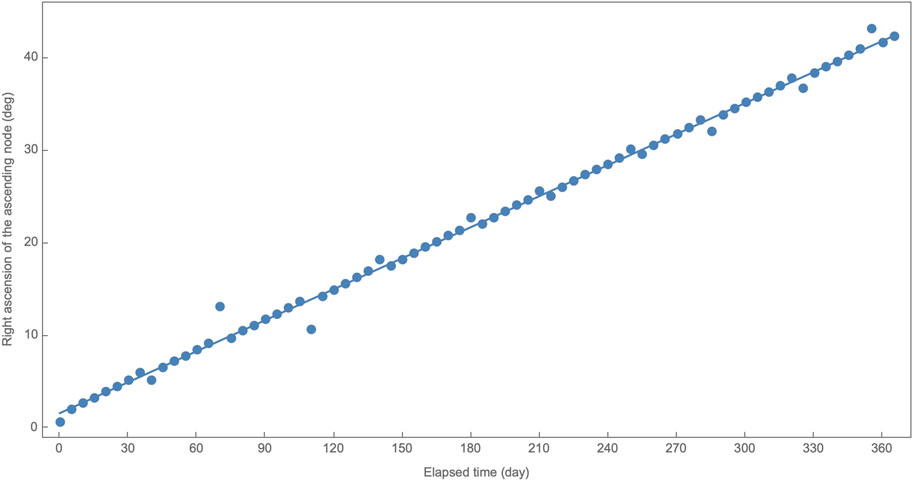
FIGURE 8. RAAN at the time of breakup. A solid line represents a fitted linear model.
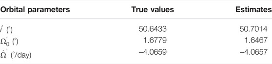
TABLE 2. Final estimation results with true values.
Given the corrected rate of change in RAAN, then Figure 9 shows a set of 74 constraints on
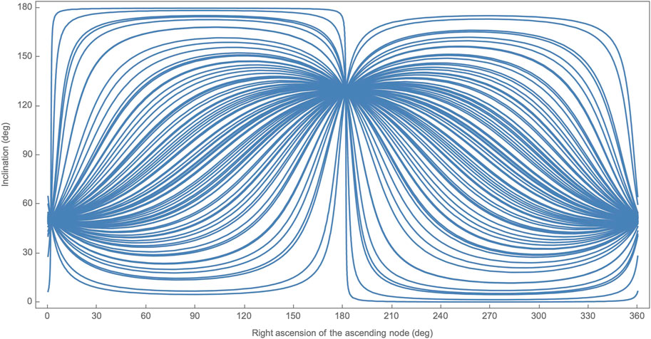
FIGURE 9. A set of 74 constrains on
4.4 Comparison
Kodama et al. (2019) found an appropriate candidate for the rate of change in RAAN and then found appropriate combinations of
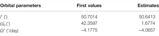
TABLE 3. First values for a nonlinear least-squares method and estimation results.
5 Conclusion
This paper has proposed a new approach to estimate the direction of angular momentum of a broken-up object at a specific time from in-situ debris measurements. This new approach does not require a nonlinear least-squares method that Tasaki et al. (2014), Fujita et al. (2016), and Kodama et al. (2019) have utilized so that there is no concern to avoid local minimal solutions. In addition, this new approach does not require a constraint equation that Kodama et al. (2019) have derived to find out candidates for the rate of change in RAAN. Instead, this approach determined the inclination of a broken-up object from the history of geocentric declination at the time of detection. Then, this approach found a candidate for the rate of change in RAAN of a broken-up object by assuming a circular orbit with a radius of the geocentric distance at the time of detection. Finally, using the constraint equation derived from the fact that a piece of debris detected shares the geocentric position vector with an in-situ debris measurement satellite, this approach estimated the RAAN at the time of breakup and calculates a correction for the candidate rate of change in RAAN.
It is desirable to have more choices for the estimation approach because it leads to an increase in the flexibility of analysis. In practical use, this new approach may provide an appropriate initial value that ultimately leads to a better estimation in a nonlinear least-squares method that Tasaki et al. (2014), Fujita et al. (2016), and Kodama et al. (2019) have utilized. It is convinced that this paper has made a great contribution in this regard. When this paper has confirmed that this new approach is effective, however, all detections are assumed to be at the line of intersection of the two orbital planes of the broken-up object and the measurement satellite. Thus, it is still necessary for practical use to develop a technique to exclude or to weight detections not following the assumptions as future work. It is also necessary for practical use to clarify the conditions under which this new approach can be applied as future work. Especially, it is necessary to verify when either a broken-up object or an in-situ debris measurement satellite is in an elliptical orbit, and when both are in elliptical orbits.
Data Availability Statement
The original contributions presented in the study are included in the article/Supplementary Material, further inquiries can be directed to the corresponding author.
Author Contributions
TH: Conceptualization, Methodology, Writing—Original Draft. KF: Data Curation, Writing—Review and Editing. YY: Data Curation, Writing—Review and Editing.
Conflict of Interest
The authors declare that the research was conducted in the absence of any commercial or financial relationships that could be construed as a potential conflict of interest.
Publisher’s Note
All claims expressed in this article are solely those of the authors and do not necessarily represent those of their affiliated organizations, or those of the publisher, the editors and the reviewers. Any product that may be evaluated in this article, or claim that may be made by its manufacturer, is not guaranteed or endorsed by the publisher.
Acknowledgments
The authors would like to acknowledge Dr. Yukihito Kitazawa, Haruhisa Matsumoto, Dr. Yuki Akiyama, Dr. Hideaki Hinagawa, and Dr. Shin’ichi Nakamura at JAXA for their useful advice on this study. The authors also would like to acknowledge Mr. Mahiro Tanahashi, an undergraduate student at Kyushu University, for his dedicated assistance on this study.
References
Aceti, R., and Drolshagen, G. (1995). Eureca post Flight Technology Investigations Achievements. Acta Astronautica 37, 347–360. doi:10.1016/0094-5765(95)00080-j
Ae, K., Uetsuhara, M., and Hanada, T. (2013). “IDEA the Project for Iin-Ssitu Debris Environmental Awareness,” in Proceedings of the Sixth European Conference on Space Debris (Darmstadt, Germany. April 22–25.
Anz-Meador, P., Ward, M., Manis, A., Nornoo, K., Dolan, B., Claunch, C., et al. (2019). “The Space Debris Sensor Experiment,” in The 1st International Orbital Debris Conference (Texas, USA. (NASA Technical Report JSC-E-DAA-TN74830).
Bauer, W., Romberg, O., and Putzar, R. (2015). Experimental Verification of an Innovative Debris Detector. Acta Astronautica 117, 49–54. doi:10.1016/j.actaastro.2015.07.008
Bauer, W., Romberg, O., Wiedemann, C., Drolshagen, G., and Vörsmann, P. (2014). Development of Iin-Ssitu Space Debris Detector. Adv. Space Res. 54 (9), 1858–1869. doi:10.1016/j.asr.2014.07.035
Doi, A. (2013). A Study on Break-Up Event Identification by Measurement of Changes in Micron-Sized Debris Environment (Master Thesis). Fukuoka, Japan: Kyushu University.
Fujita, K., Tasaki, M., Furumoto, M., and Hanada, T. (2016). An Orbit Determination from Debris Impacts on Measurement Satellites. Adv. Space Res. 57 (2), 620–626. doi:10.1016/j.asr.2015.11.005
Furumoto, M., Fujita, K., and Hanada, T. (2015). Dynamic Modeling on Micron-Size Orbital Debris EnvironmentInternational Symposium on Space Technology and Science (ISTS). Japan: Kobe-Hyogo. Paper ISTS-r-12, presented at the ThirtiethJuly 4-10.
Furumoto, M., Fujita, K., Hanada, T., Matsumoto, H., and Kitazawa, Y. (2017). Orbital Plane Constraint Applicable for Iin-Ssitu Measurement of Sub-millimeter-size Debris. Adv. Space Res. 59 (6), 1599–1606. doi:10.1016/j.asr.2016.12.036
Goldstein, R. M., Goldstein, S. J., and Kessler, D. J. (1998). Radar Observations of Space Debris. Planet. Space Sci. 46 (8), 1007–1013. doi:10.1016/s0032-0633(98)00026-9
Hanada, T. (2013). Orbital Debris Modeling and Applications at Kyushu University. Proced. Eng. 67, 404–411. doi:10.1016/j.proeng.2013.12.040
Kitazawa, Y., Matsumoto, H., Okudaira, O., Kimoto, Y., Hanada, T., Faure, P., et al. (2013). “Research and Development on In-Ssitu Measurement Sensors for Micro-meteoroid and Small Space Debris at JAXA,” in Proceedings of the Sixth European Conference on Space Debris (Darmstadt, Germany.
Kodama, Y., Furumoto, M., Yoshimura, Y., Fujita, K., and Hanada, T. (2019). Estimation of Orbital Parameters of Broken-Up Objects from In-Ssitu Debris Measurements. Adv. Space Res. 63 (1), 394–403. doi:10.1016/j.asr.2018.07.034
Matney, M., Goldstein, R., Kessler, D., and Stansbery, E. (1999). Recent Results from Goldstone Orbital Debris Radar. Adv. Space Res. 23 (1), 5–12. doi:10.1016/s0273-1177(98)00224-5
McDonnell, J. A. M., Deshpande, S. P., Niblett, D. H., Neish, M. J., and Newman, P. J. (1993). The Near Earth Space Impact Environment - an LDEF Overview. Adv. Space Res. 13 (8), 87–101. doi:10.1016/0273-1177(93)90572-s
Oikonomidou, X., Braun, V., Pail, R., Gruber, T., Schummer, F., Meßmann, D., et al. (2021). “MOVE-III: An In-Situ Detector to Support Space Debris Model Validation,” in Proceedings of the Eighth European Conference on Space Debris (Virtual) (Darmstadt, Germany.
Stokely, C. L., Stansbery, E. G., and Goldstein, R. M. (2009). Debris Flux Comparisons from the Goldstone Radar, Haystack Radar, and Hax Radar Prior, during, and after the Last Solar Maximum. Adv. Space Res. 44 (3), 364–370. doi:10.1016/j.asr.2009.02.005
Keywords: space debris, in-situ measurements, orbit estimation, satellite fragmentation, origin identification
Citation: Hanada T, Fujita K and Yoshimura Y (2022) Estimation of Orbital Parameters of Broken-Up Objects From In-Situ Debris Measurements. Front. Space Technol. 3:867236. doi: 10.3389/frspt.2022.867236
Received: 31 January 2022; Accepted: 07 March 2022;
Published: 11 April 2022.
Edited by:
Yukihito Kitazawa, Japan Aerospace Exploration Agency (JAXA), JapanReviewed by:
Jorge Kennety Silva Formiga, São Paulo State University, BrazilHironori Sahara, Tokyo Metropolitan University, Japan
Copyright © 2022 Hanada, Fujita and Yoshimura. This is an open-access article distributed under the terms of the Creative Commons Attribution License (CC BY). The use, distribution or reproduction in other forums is permitted, provided the original author(s) and the copyright owner(s) are credited and that the original publication in this journal is cited, in accordance with accepted academic practice. No use, distribution or reproduction is permitted which does not comply with these terms.
*Correspondence: Toshiya Hanada, aGFuYWRhLnRvc2hpeWEuMjkzQG0ua3l1c2h1LXUuYWMuanA=