 Muhammad Hasif Bin Azami1,2*
 Necmi Cihan Orger1*Victor Hugo Schulz1Takashi Oshiro1Jose Rodrigo Cordova Alarcon1Abhas Maskey3Kazuhiro Nakayama4Yoshiya Fukuda4Kaname Kojima5
 Takashi Yamauchi1Hirokazu Masui1Mengu Cho1,6* KITSUNE Team Members1
- 1Laboratory of Lean Satellite Enterprises and In-Orbit Experiments (LaSEINE), Department of Electrical and Space Systems Engineering, Kyushu Institute of Technology, Kitakyushu, Japan
- 2Centre for Satellite Communication, School of Electrical Engineering, College of Engineering, Universiti Teknologi MARA, Shah Alam, Selangor, Malaysia
- 3Antarikchya Pratisthan Nepal, Kathmandu, Nepal
- 4Harada Seiki Co., Ltd., Hamamatsu, Japan
- 5Addnics Corp., Tokyo, Japan
- 6School of Electrical and Electronic Engineering, Nanyang Technological University, Singapore, Singapore
Earth observation (EO) missions remain a challenging task for small satellite platforms due to their demanding requirements and space environment effects. In this study, the camera payload development and mission requirements are presented together with the ground-based testing results for a 6U CubeSat called KITSUNE, operating at low Earth orbit. The major challenge of the payload development is maintaining the focus of the optical system despite the thermal vacuum environment in orbit since the low thermal capacity and rapid temperature variation of CubeSats hinder the camera focus. First, the payload is developed with an objective of a 5-m-class imaging mission, which has a 31.4 MP CMOS sensor and a lens with a 300-mm focal length. Second, polyimide heaters and multilayer insulators are utilized in order to maintain focus during imaging operations. Third, a collimator lens is used to aid in image capture during thermal vacuum tests. These images are analyzed thoroughly using various focus measure operators. The Diagonal Laplacian was found to be the most suitable operator due to the consistency in test results. The results also showed that the heat generated by the camera sensor significantly affects the lens temperature and, ultimately, the target temperature of the lens was defined at −1.8°C. Finally, the test results are discussed, including thermal vacuum, vibration, total ionization dose, and the effect of exposure to direct sunlight on the CMOS sensor.
1 Introduction
A CubeSat is a miniaturized satellite under the nanosatellite class between 1 and 10 kg, which also could be categorized in unit form factors from 1 to 27 U (Poghosyan and Golkar, 2017). For instance, EG 3, El Camino Real, and Palisade were the largest 16 U CubeSats launched in20191,2,3. As of December 2021, thousands of CubeSats have been launched into space from institutions, governments, space agencies, and the private sector, as reported by BryceTech in a 2022 publication4. Figure 1 shows the CubeSat (1–10 kg) missions launched between 2003 and 2020 based on data from Kyushu Institute of Technology (Kyutech) small satellite database, and in this study, the missions are divided into five categories: 1) communication, 2) education, 3) remote sensing, 4) scientific, and 5) technology. During the classification process, the CubeSats designed for amateur radio communication are under the communication missions, whereas the education mission covers the university-based satellites. Furthermore, any missions related to applied space science and payload demonstration are classified as scientific and technology missions. According to these results, remote-sensing missions have been in high demand throughout the last decade, followed by technological development and scientific missions. For instance, Planet and Spire have launched a constellation of CubeSats for remote-sensing applications (Toth and Jóźków, 2016). Therefore, it shows the importance and feasibility of the remote-sensing mission applied by the CubeSat platform.
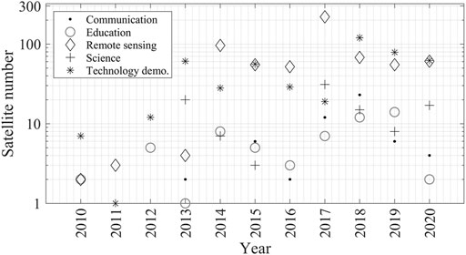
FIGURE 1. Kyutech database of CubeSat mission (1–10 kg) between 2010 and 2020.
Earth observation (EO) missions, also known as Earth remote sensing, have various categories depending on the point of interest, which could be a wide range of applications, such as geosciences, natural disaster monitoring, city planning, observing urban heat island effects, agriculture/crop monitoring and so on (Houborg and McCabe, 2016; Chirayath and Li, 2019; Khanal et al., 2020; Salguero et al., 2020). As a result, these applications require the performing of a wide range of measurements on the atmosphere, ocean and landscape that cover the rural regions to the densest city areas (Blackwell et al., 2014; Cooley et al., 2017; Mas et al., 2017). Furthermore, these applications also depend on the payload/instrument type and the orbit of the satellite, which significantly influence the performance of the mission. For instance, it could be a CMOS sensor working at the visible wavelength in low Earth orbit (LEO) or a microwave sensor in the geostationary orbit (GEO), and both missions work by measuring the reflection and emission of electromagnetic radiation from Earth. Thus, after the mission objective is proposed, there are several aspects to study in order to determine the feasibility, especially for a small satellite platform with limited resources with regard to size, weight, and power (SWaP).
Determining the spatial and spectral resolution of an imaging system could significantly help the development process by considering the satellite system (e.g., satellite resources (SWaP) and downlink capability) and orbit parameters (e.g., revisit time and ground coverage) during the initial planning and development phase. For example, high spatial (3-m) and multispectral cameras (VIS and NIR) have been installed onboard Dove Planet constellation 3 U CubeSats and utilizing a custom X-band high-speed downlink (HSD) radio, which is capable of downlinking volumes of 12–15 GB in a single ground station (GS) pass (Devaraj et al., 2017). The satellites were launched at 500 km sun-synchronous orbit (SSO) to achieve a sufficient imaging swath width. Hence, the private space company showed the successful swarm mission, which could increase the number of CubeSat launched into space with considerably high reliability.
Despite a large number of CubeSats having been launched, mission success should also be considered to verify the reliability of the development and launching of a CubeSat (Bouwmeester et al., 2022). The success levels are well-defined, from level 0 (manifested) to level 5 (mission success) (Pradhan and Cho, 2020). K. K. Pradhan and M. Cho discussed that the success rate of CubeSats built by the university and that of the combined government and private agencies are slightly different, namely, 50.0% and 68.0%, respectively. The causes of CubeSat mission success have been debated enormously among the developers based on the lessons learned and experienced in the particular CubeSat projects. One factor affecting mission success was the design of the on-ground tests before the satellite was launched into space.
Several CubeSat imaging payloads have been tested and reported for space environment tests as well as the functionality test. Douglas et al. (2021) and Morgan et al. (2021) discussed the deformable mirror (DeMi) payload for 6U CubeSat design, integration, and environmental testing. A similar CubeSat size named ASTERIA was also designed and tested for its space telescope mission (Smith et al., 2018). Besides that, a high-resolution image and video (HiREV) payload on a 6 U CubeSat was developed by the Korea Aerospace Research Institute (KARI), which discussed the results of the space environmental testing (Cho et al., 2019). However, the studies are limited to the vibration test (VT) and thermal vacuum test (TVT) for the payload without including other tests such as those for radiation and the effect of direct sunlight.
In order to develop a CubeSat, several tests should be completely performed on the ground, simulating orbit conditions in space. The space environment tests, such as radiation, thermal vacuum, and vibration tests are commonly used for traditional satellites. The Japan Aerospace Exploration Agency (JAXA) has published the standards named JAXA Management Requirement (JMR) and JAXA Engineering Requirement Guideline (JERG), and the European Space Agency (ESA) has established a standard called the European Cooperation for Space Standardization (ECSS) (Okada et al., 2009; Idzikowska, 2017). ISO-19683 describes the minimum test requirements for small spacecraft, including for CubeSats. Thus, referring to the available guidelines from JAXA and ESA handbooks could be helpful during CubeSat development. Although the guidelines could improve payload testing, they do not thoroughly discuss imaging system verification, particularly on the CubeSat platform. This study is exclusive and worth publishing since it applies to an imaging payload with an active/passive temperature control system integrated on a small satellite platform, which has significantly limited SWAP resources compared to traditional satellites. The KITSUNE imaging payload has been tested with multiple space environment tests and image focus analyses. Preliminary on-orbit data is also discussed in order to compare with on-ground tests.
The small satellite in this study is a 6 U CubeSat named KITSUNE, which is currently operating in low Earth orbit (LEO). It is a collaboration project between three universities and two Japanese private companies: the Kyushu Institute of Technology (Kyutech), Harada Seiki Co. Ltd., Addnics Corp., Nanyang Technological University (NTU), and the Arthur C. Clarke Institute for Modern Technologies (ACCIMT). The project began in September 2019, and the satellite was deployed through the JAXA Kibo module on 24 March 2022.
The main objective of this paper is to present the design, testing, and verification of the imaging payload design for a 6 U CubeSat. The paper is divided into six sections, with Section 2 focusing on the imaging payload design. The thermal model design is described in Section 3. The space environment tests and long-duration operational test results are shown in Section 4. The preliminary on-orbit operation data is discussed in Section 5. Finally, the discussion and conclusion of the study are provided in Sections 6,7, respectively.
2 Imaging payload design
2.1 KITSUNE mission overview
The name KITSUNE was selected based on the mission and development objectives: Kyutech standardized bus, Imaging Technology System, Utilization of Networking, and Electron content measurement. Kyutech has developed a standardized bus system for 1U CubeSats, and it has been expanded to a 2 U bus system for KITSUNE satellite by improving capabilities of attitude control and downlink speed. C-band communication link is the first experience for Kyutech to implement onboard a CubeSat, which communicates with a main and mobile ground station (GS). A 3 U imaging payload, 2 U main bus system, and 1U SPATIUM-2 compose the 6 U CubeSat platform. The SPATIUM-2 (Space Precision Atomic-Clock Timing Utility Mission) is controlled by non-amateur-radio frequencies and has its own bus system while receiving only battery power from the 2 U main bus system (Kishimoto et al., 2021). Therefore, KITSUNE could be described as a dual-satellite system, and the 2 U main bus system controls the 3 U camera payload and uses amateur-radio frequencies. Since the topic of this paper is 3U camera payload development and testing, only the 2 U main bus system and 3 U camera payload are explained in detail. The four primary mission goals for the segment controlled by the amateur radio-frequencies are as follows:
1) Earth observation with 5-m-class resolution of visible spectrum images.
2) Development of a 2 U Kyutech standard bus system.
3) Downlink of a low-resolution 2-MP image from a secondary camera by C-band uplink as an amateur-radio service.
4) Demonstration of C-band communication with the main and mobile GSs.
In the early stages of development, the idea behind KITSUNE was to photograph colored patterns or figures inside a 100-m x 100-m space for entertainment and social reasons. The primary objective was to deliver a 5-m class imaging service per the mission statement, while wildfire image categorization is included as a secondary objective to maximize the value of the imaging payload. As a result, the following success criteria were determined as below:
1) Minimum success with downlinking a full image with or without focus to the GS.
2) Full success with capturing any letters or characters done by a group of people within a 100-m x 100-m space.
3) Extra success with capturing images with 5-m-class resolution (5 m/pixel) and correctly classifying wildfire images.
The payload system requirements are introduced concerning the mission statements and objectives. In order to support the listed system requirements, the design and verification requirements are as follows:
1) The payload should be able to fit inside a 3U volume of 90.0 mm × 90.0 mm x 327.5 mm and have a total mass of ≤7 kg.
2) The camera controller board (CCB) and camera sensor should be able to withstand the harsh space environment of vacuum, radiation, and wide temperature range (−20 to +50°C).
3) The ground resolution and swath should be able to capture an image in 5 m/pixel and within 20 km.
4) The payload should capture RGB images with the correct colors using JPG compression.
5) The total power consumption of the payload should be less than 10 Wh per orbit.
6) The payload should be able to capture six images per command by uplink commands via UHF and C-band communications.
2.2 Payload design
The 1 U BIRDS CubeSat project bus systems were created by the Kyutech bus system team (Kim et al., 2021). For KITSUNE, 2 U main bus systems have been built with a significant heritage from the BIRDS project while improving and expanding some of the capabilities of the bus system, such as battery capacity, the number of interfaces, high-speed data downlink, and attitude control. On a backplane board (BPB), the onboard computer (OBC), electrical power system (EPS), attitude determination and control system (ADCS), and communication system (COM) are thoughtfully positioned horizontally (Figure 2). Integrating the BPB is primarily done to prevent harness connection failure. A pair of PIC microcontrollers in the OBC of KITSUNE acts as a command and data handling (C&DH) and communication device to send the CubeSat beacon. The EPS also has the significant duty of providing enough power to the various bus systems and payload. Thirty-four solar cells were attached to each external face (except the one on the -Z-axis) with 14 W of maximum generation. In addition, the KITSUNE bus system uses the MAI-401 active control module, which is a commercial off-the-shelf (COTS) product. The module is built-in with reaction wheels and connects to a GPS and magnetometer from the other boards (ADCS adapter board and access and deployment board). In order to eliminate electromagnetic noise from the reaction wheels, the magnetometer is placed at a 10.0-cm distance from the ADCS module, and the GPS is mounted on the -Y-axis solar panel. KITSUNE is equipped with C-band and ultra-high-frequency (UHF) transceivers for uplink and downlink operations. The UHF receives uplink commands and transmits (downlinks) the thumbnail photos, telemetry, and continuous wave (CW) beacon, while the C-band transceiver is mainly utilized to downlink the full image data collected by the payload but could also receive uplink commands.
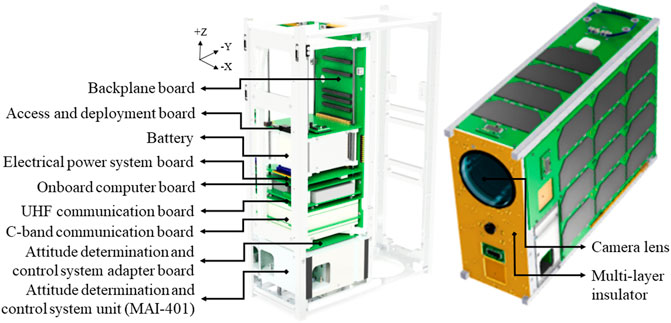
FIGURE 2. KITSUNE 6 U CubeSat configuration.
A harness connects three significant parts of the 3 U imaging payload to the 2 U main bus network. The camera controller board (CCB), camera sensor (CAM), and camera lens are all carefully crafted and selected to fulfill the mission objectives. Installed on the CCB was a Raspberry Pi Compute Module 3+ (RPi CM3+), which connects to and manages a COTS CMOS camera sensor (31.4 MP), as summarized in Table 1. A 300-mm RICOH custom-made lens was capable of capturing images with a resolution of 6,464 × 4,852 pixels. The sensor pixels and lens focal length of this payload have been chosen to provide a 5-m resolution based on Eq. 1:
where f is the lens’s focal length, pxsize is the pixel size, h is the satellite altitude, and GSD is the ground sample distance. The altitude used in the calculation is 380–420 km. Thus, the GSD with perfect nadir pointing is estimated as 4.4 m at 380 km and 4.8 m at 420 km. Since a pointing error is anticipated during ADCS operation in nadir-pointing mode, the actual GSD could be larger than 4.4 m or 4.8 m while capturing image sequences.
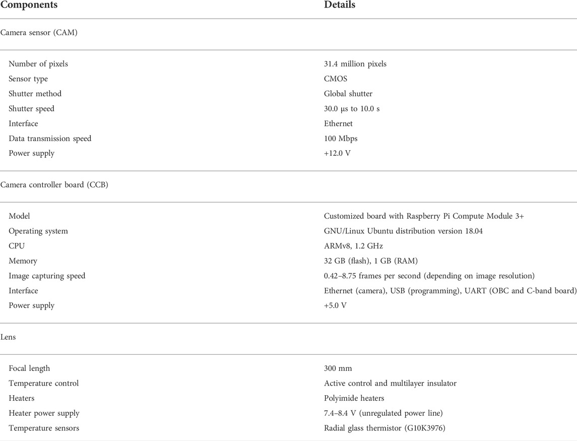
TABLE 1. Imaging payload specifications.
3 Thermal model design
Since the focal length should be maintained while executing the imaging mission, the temperature should be maintained to within a few degrees from the set temperature of each lens component, which imposes more stringent requirements on the thermal design compared to the other subsystems. The thermal model requires the reproduction of the camera structure model to accurately create the thermal-mathematical model. In addition, it is also important to reproduce the thermal resistance between the camera unit and the satellite structure. In this study, the thermal analysis was performed by Thermal Desktop© software.
The thermal-mathematical model was created without relying heavily on on-orbit data (as it was done for 1 U missions at our institute) since KITSUNE is the first 6U CubeSat developed by Kyutech. However, some parameters used in previous 1 U satellite systems could still be applied to the 6 U satellite model, such as optical properties, thermo-physical properties, and thermal contact conductance. The optical properties depend on the surface condition of the material (e.g., color and roughness). The thermal conductivity, specific heat, and density of the material are under the thermo-physical properties. Meanwhile, thermal conductance is the value of heat transfer between the contact surfaces of the two materials. Furthermore, an accurate thermal-mathematical model cannot be acquired without conducting a thermal balance test (Figure 3). Due to targeting a short development time, a structure thermal model (STM) is not produced before the engineering model (EM). Thus, a camera thermal-mathematical model was created based on data from the thermal balance test for a 3 U camera payload. The thermal balance test consisted of one cycle of high and low temperatures, with 36 temperature measurement points, including temperature measurement for the external heater.
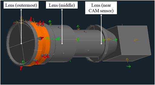
FIGURE 3. Thermal-mathematical model of the imaging payload.
By reflecting the results of this test in the thermal-mathematical model, it is possible to determine the level of the camera structure details that need to be reproduced in the thermal analysis software. In this study, the difference between the analytical and experimental values is aimed to be within ±5.0°C, and the thermal-mathematical model of the camera was finalized after approximately 70 iterations of parameter adjustment and analysis. Afterwards, the completed camera model was used to perform an on-orbit temperature analysis. As a result, it was observed that the lens temperature had a wide range of temperature fluctuations, and it could not meet the design requirements without active or passive control methods. First, three additional insulation controls were applied to the lens and the bus system. The first step was to mount multilayer insulation (MLI). It was applied on the outer lens case to insulate the heat exchange by radiation between the satellite structure and the camera payload, and MLI was also installed on the -Z outer panel to insulate the satellite structure and space heat exchange. The second step was to use glass epoxy spacers between the payload mount and the satellite structure for further insulation. Finally, the third step was placing a protector glass cover over the outermost lens to prevent heat from escaping to space. These revisions in the thermal design were evaluated to be sufficient in the simulations.
After EM was electrically and mechanically integrated, the thermal balance test was conducted. Two cycles of high and low temperatures were planned with 79 temperature measurement points. The temperature data obtained from the test was used to create a thermal-mathematical model of the entire satellite. As for the payload, the thermal model was already calibrated in the previous thermal balance test, and a temperature difference of ±2.0 or ±1.0°C was achieved with a high reproducibility rate when comparing the results between the actual and the analysis, respectively. Although the STM thermal test is not conducted due to the competitive development time, the thermal-mathematical model was created through a subsystem-level thermal balance test prior to the integrated EM test. In the analysis, the satellite orbit and attitude conditions were defined as follows:
1) Altitude: 400 km.
2) Beta angle: 0, 30, 45, 60, 75°.
3) Satellite attitude: sun-pointing mode and nadir-pointing mode.
4) Period: 80,000 s.
Once the passive insulation control was applied to the camera, the temperature fluctuation range of the lens was significantly reduced. Based on these analytic results, the mission operation is planned as discussed by (Azami et al., 2022). By considering the potential difference between the analysis results and the on-orbit temperatures, an active temperature control system was also added to the payload. It consists of two polyimide and three temperature sensors placed under the MLI and the lens cover.
After the EM development, two thermal vacuum tests were conducted using the KITSUNE flight model (FM). Since heater performance had not been tested before the camera heater performance test was conducted, the results were reflected in the thermal-mathematical model to determine the lens target temperature. The overall system was verified in the second FM test. Besides that, according to the analysis, the predicted lens (outermost) temperature at 30 degrees of beta angle was −7.2°C. The beta angle is the angle calculated between the orbital plane and the vector from the Sun. The mission could be carried out even if the actual orbit temperature is higher than the analysis temperature and high temperature of the lens will affect the image focus, where the mission is suggested to execute during the low beta angle. On the other hand, if the temperature is lower than the set lens temperature, the heater will be used to increase the lens temperature. The analysis results concluded that the mission could be carried out even if there is an error of ±5.0°C in the measured temperature.
4 On-ground test results
The KITSUNE imaging payload was tested thoroughly on-ground, starting from the breadboard model (BBM) to the flight model (FM), as summarized in Figure 4. The BBM consists of RPi CM3+, CAM sensor, and COTS Nikon lens, since the actual custom-made lens was in the fabrication process during the BBM tests. A similar focal length, 300 mm, was used to minimize the test variables. Besides that, the difference between EM 1 and 2 was the test being conducted at the payload unit level and satellite system level, respectively. Several thermal vacuum (TVT) and vibration tests (VT) were conducted with distinctive parameters according to the test plans. The TVT for the KITSUNE EM 1 imaging payload was conducted with one less cycle compared to the EM 2 version since the objective was the preliminary verification of the payload in harshly cold and hot temperatures. However, the EM 1 version went through VT twice due to small cracks on the lens and a component inside the CAM sensor electronics that had become detached during the first attempt. The second VT was successful without any detected issues, leading to the improved payload version (EM 2). Before the second version of the camera payload, FM was designed and tested at the acceptance test (AT) level, and the payload unit of EM 2 was run at the qualification test (QT) level. The FM version was tested with a similar test plan as EM 2 for the TVT but with less stress on the VT. Lastly, after completing the space environmental tests, a long-duration operational test (LDOT) was carried out for about 25 days to verify the mission operation inside a clean room. These tests will be explained in detail throughout the following sub-sections.
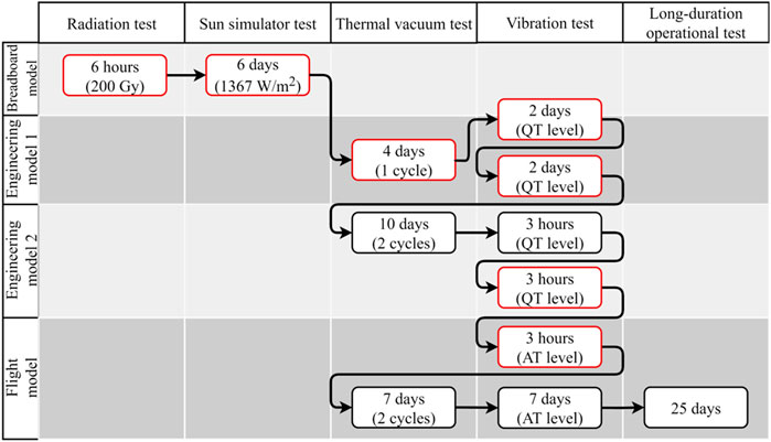
FIGURE 4. Summary of KITSUNE imaging payload development tests (red rectangle shows payload unit level tests and black rectangle shows satellite system level tests).
4.1 Space environment tests
Several functionality tests (FTs) were performed to verify the communications and interfaces between the bus system and the imaging payload. Before, during and after each space environment tests, FTs were conducted to be as similar as possible to the actual CubeSat operation in orbit in order to achieve reliable results. The space environment tests were divided into total ionization dose (TID) radiation test, Sun simulator test, thermal vacuum test (TVT), and vibration test (VT). Finally, the LDOT was performed to extensively execute the mission with multiple commands and the produced data was analyzed. As discussed in Section 3, the KITSUNE imaging payload EM (unit level) was tested ahead of time for TVT to design the thermal model. However, in this section, the KITSUNE FM (satellite system level) tests are discussed thoroughly to present and compare the results with the obtained on-orbit data.
4.1.1 Total ionization dose radiation test
The first space environment test conducted was total ionization dose (TID), in which the RPi CM3+ was the device under test (DUT). Radiated particles in space could cause catastrophic damage to the electrical components onboard a CubeSat. The main objective of the TID test was to verify that the DUT could operate and communicate in the radiated environment with no instabilities. Two important components, the central processing unit (CPU) and the embedded multimedia card (eMMC), were observed by executing the test codes. The second objective was to measure the power consumption of the DUT during the TID test. The DUT was set up and exposed to a radiation source of Co-60 for six-hour (equal to 200 Gy radiation dose in two years of operation in LEO) in the radiation chamber at Kyushu University, Japan. For comparison, Toumbas (2018) conducted a TID test on RPi CM3, while Slater et al. (2020) used Jetson Nano as the DUT. However, the distinction between the present test and those others was the type of radiation source and energy levels. Overall, the objectives were justified by comparing the results between the FTs before, during, and after the TID test. An anomaly of a single event latch-up was detected during the TID test and discussed extensively (Azami et al., 2022). A similar issue could not compromise the actual operation because the imaging mission was designed to only turn on the RPi CM3+ for the required time to capture images, thus it can successfully recover from such anomalies. During the TID test, a reset of the subsystem by the power cycle was enough to restore its nominal state of operation.
4.1.2 Sun simulator test
The camera sensor installed onboard KITSUNE was a complementary metal-oxide-semiconductor (CMOS) type, as explained in Table 1. In this study, the Sun simulator test aimed to study the effects of sunlight on the CAM sensor and verify the survival of the sensor facing directly toward the Sun. The light intensity was set for 1,367 W/m2, measured by the pyranometer, as illustrated in Figure 5. The DUT used in this test was dissimilar from the KITSUNE CAM sensor, particularly in pixel resolution, but the pixel size, shutter type, and sensor manufacture were identical. This test uses a low-cost CMOS sensor instead of the KITSUNE CAM sensor.
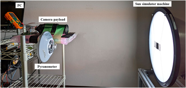
FIGURE 5. Total Ionization Dose (TID) radiation test setup.
A thermocouple was placed behind the CAM sensor to measure the temperature change during the Sun simulator test. Initially, the distance between the Sun simulator machine and the camera payload was measured using the reading from the pyranometer, which was 10.0 mV (equivalent to 1,367 W/m2). The test procedures are listed as follows:
1) Taking photos of a white background as the pre-functionality test.
2) Disconnecting the CAM sensor from the RPi CM3+.
3) Exposing the CAM sensor to the Sun simulator machine.
4) Recording the temperature reading.
5) Turning off the Sun simulator machine.
6) Re-connecting the CAM sensor to the RPi CM3+.
7) Taking a photo of the white background (the same as during pre-FT).
8) Repeating steps 2 to 7 by increasing the exposure time to 10 s.
The RGB images captured each time after the exposure were converted to grayscale color to have reliable results in the standard deviation value of pixel intensity numbers based on the image histogram. Figure 6 shows that the standard deviation value for the number of pixels were significantly reduced after the CAM sensor was exposed to the Sun simulator machine for 10 s, in addition to the temperature measured during the test. Based on the histogram chart, the intensity value shifted towards the dark region (to the left histogram) at 0.03% only after the CAM sensor was exposed to the Sun simulator machine for 180 s. However, the CAM sensor was recovered after the sixth day of the test showing that the standard deviation value was 67.0% (65.0% for pre-FT). The yellowish-colored images captured during the test might be due to the heat regularly affecting the sensor while restoring after being away from the Sun simulator for several days. Meanwhile, the temperature readings did not show any significant instability, and the risk for the CAM sensor was determined to be an acceptable level, since it was within the operational temperature range specified by the manufacturer. Therefore, the test verified the objectives and functions of the CAM sensor if it was directly exposed to the Sun in space during the satellite deployment or in case of loss of attitude control. The result also confirmed that a protected lens cover was not required on the KITSUNE FM design.
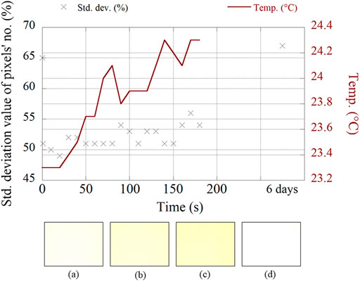
FIGURE 6. Standard deviation value of pixel intensity and sensor temperature readings during the sun simulator test: (A) pre-functionality test, (B) after less than 1 s exposed, (C) after 180 s exposed, and (D) after 6 days with no exposure.
4.1.3 Thermal vacuum test
The thermal vacuum test (TVT) was an important test to simulate the CubeSat operation in a harsh environment, the worst hot and cold in a vacuum. The imaging payload has been tested in the unit and at satellite system levels. This study will focus on the results of the KITSUNE FM TVT. The aim was to verify the functionality of the payload from the uplink execution command to downlink image data in two cycles between −15.0 and +60.0°C, according to the BIRDS project test (Azami et al., 2019; Kim et al., 2021) and ISO 19683 Space systems—design qualification and acceptance tests of small spacecraft and units. The CubeSat was precisely placed inside the thermal chamber, and a collimator lens was straight levelled at the outer chamber, pointing towards the target lens through the chamber window, as illustrated in Figure 7. An additional light source was also arranged facing the target lens to acquire clear images during the test.
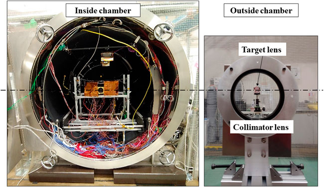
FIGURE 7. Thermal vacuum test (TVT) setup.
The thermal cycle profile was set as originally planned during the KITSUNE FM TVT for two cycles (two cold and two hot), as shown in Figure 8. At the extreme cold (−15.0°C) and hot temperatures (+60.0°C) of each cycle, soaking time took about half an hour, with another half an hour for the FT of the camera and other missions. In addition, 42 temperature measurement points using thermocouples (model type-T) were attached using polyimide Kapton tape on the designated positions, including 9 sensors on the external panels and 5 sensors on the camera payload (one on the CCB, two on the CAM sensor, and two on the CAM lens). Overall, the monitoring and control temperature values were set by averaging the six external panels of the measurement points from the beginning of the test to the end using the LabVIEW program with 3 samples per minute including timestamp output.

FIGURE 8. Temperature readings of KITSUNE flight model thermal vacuum test for two cycles.
The temperature measurements of the camera controller board (CCB), camera sensor (CAM), and average external panels were also collected and plotted in Figure 8, where the vacuum condition was set between FT1 and FT7. The temperature of the external panels showed that the KITSUNE FM undergoes two thermal cycles with a designated temperature range. Based on the graph, the temperature readings of the CCB and CAM significantly increased in a short period during the FTs of the imaging mission. Nevertheless, at FT 5 and 6, the temperature reading of the CCB increased sharply due to operating secondary missions with other payloads. Besides that, a study by Cho et al. (2019) was conducted to test a 6U CubeSat for TVT in three cycles between −19.0 and +46.0°C, including a ±15°C margin. In the KITSUNE project, the TVTs were performed at the unit and satellite system levels while analyzing the image focus during the test.
The TVT objective was carried out by executing the imaging mission in each FT point. The image focus was analyzed using several normalized focus measure operators: gradient-based, Laplacian-based, wavelet-based, statistic-based, and discrete cosine transform-based. Pertuz et al. (2013) discussed that the gradient-based and Laplacian-based were the best measure operators for the image edges. Five operators have been chosen in this study: 1) Gaussian derivative, 2) Tenengrad variance, 3) modified Laplacian, 4) diagonal Laplacian, and 5) variance of Laplacian, which were at the top in the ranking for the Sony camera sensor. Ultimately, the diagonal Laplacian operator has been chosen as the significantly suitable approach due to the consistency in TVT as well as VT results. Based on Figure 9, the highest focus measured was at FT4, 100% focus at +12.5°C in vacuum conditions, with a number closer to 1.0 indicating better focus. Meanwhile, the FT0 image was the lowest focus measure, which was 74.3% at atmospheric room temperature. The camera focus was significantly affected by the pressure level (atmospheric or vacuum) and temperature differences as shown in Figure 9, where FT1 (in vacuum condition) was higher in focus measured than FT0 (in atmospheric condition) since it was increased by 6.3%. Under the same vacuum condition, FT2 showed better focus, which increased by 17.8% from the FT1 result because of the different lens temperatures. Therefore, the KITSUNE FM camera payload could have an optimal focus (above 95.0% focus measured) between -1.8 and +12.5°C, based on the TVT results in the vacuum conditions.
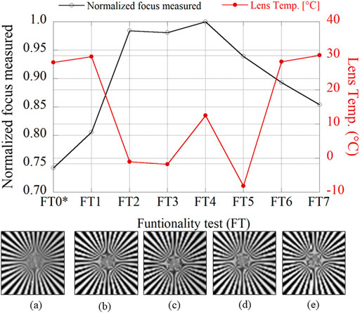
FIGURE 9. Result of normalized focus measured on the image of the target lens captured during each functionality test (FT) with the lens temperature measured during (A) FT0*(atmospheric condition), (B) FT1, (C) FT2, (D) FT3 and (E) FT4.
4.1.4 Vibration test
The final space environment test was the vibration test that aimed to imitate the CubeSat condition during the rocket launching. The KITSUNE CubeSat was planned to be launched using the Orbital Cygnus vehicle. Therefore, the respected acceleration profile was set for an AT level of 4.08 Grms random vibration for 60.0 s. The condition of the camera payload was verified by inspecting the lens and comparing the images captured between the pre-VT and post-VT functionality tests. The position of KITSUNE FM on the vibration machine was manually changed depending on the tested axis, where a careful inspection was carried out after VT to detect any cracks or shifted screws, neither were found. Using a similar method from TVT to measure image focus (diagonal Laplacian operator), the VT result showed no notable change, only reduced by 0.48% focus change. The positive result on KITSUNE FM was gained from the extensive tests on the unit level, which showed a crack on the lens and a component detached from the camera sensor circuit board. Besides that, (Cho et al., 2019) tested the 6U CubeSat using higher RMS acceleration and duration values compared to KITSUNE VT. The specification settings of VT were highly dependent on the launch services. Overall, the payload of KITSUNE FM passed the FTs after system level VT without displaying any errors, including the communication interface. Thus, the VT was important for assurance of a successful mission and the safety of the launch vehicle.
4.2 Long-duration operational test
Before the CubeSat was delivered to JAXA, LDOT was extensively carried out with the GS radio and terminal node controller (TNC) in a clean-room environment. The LDOT was crucial to validate the software design of the imaging payload, which should be executed smoothly and without any bugs. Each mission scenario was executed with multiple uplink commands to KITSUNE using real wireless UHF and C-band communication. For instance, the take-photo command was sent via UHF uplink, and later the full JPG image was downlinked through the C-band. Meanwhile, a serial cable was only connected to the CubeSat for monitoring and debugging purposes. The LDOT was conducted over several days to find and resolve software bugs. The crucial task was to determine the accurate timing of mission execution, given the limitation of the camera payload specifications: the interface communication speed and sensor capturing speed in frames per second (fps). Besides that, the leading question was verifying whether the imaging mission could be executed while image data sequentially being downlinked in a pass window or later. Thus, the CubeSat was connected to a power supply where battery charging and discharging conditions similar to those in on-orbit operation were simulated to demonstrate the mission feasibility in terms of the power budget.
The end-to-end test of the imaging mission was demonstrated in three passes. The initial pass was programmed to capture six photos at the desired time and coordinate through the UHF uplink command. The ADCS was also set to nadir pointing mode an hour before the camera sensor turned on to stabilize and correctly point to the Earth. Figure 10 shows the power consumption for taking the photos and copying the image thumbnails to the OBC shared flash memory during the first pass. Based on the graph, the 12-V power line (dotted shape) was designated for the camera sensor, the CCB used the 5-V power line (x shape), and the overall power line (round shape) indicated the total power consumption, including from the main bus systems. The overall energy consumed at this pass was approximately 2.90 Wh.
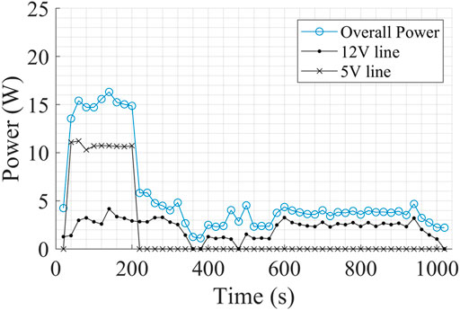
FIGURE 10. Power consumption of KITSUNE camera capture mission (first pass).
In addition to the image capture, the CCB was programmed to also compress the data into PNG and JPG format files as well as to generate thumbnails of 160 × 120 px. The mission scenario of the second pass was to downlink the thumbnails through UHF communication before retrieving the complete targeted PNG/JPG image data via the C-band. Overall, the energy consumed was 2.81 Wh. Referring to Figure 11, the commands sent were as follows:
1) Uplink command to get the last address of image data through UHF (x shape) at 104 s.
2) Downlink six thumbnails through UHF between 160 and 192 s.
3) Downlink the complete JPG data through C-band in real time (dotted shape) between 507 and 637 s.
4) Downlink corresponding ADCS housekeeping data through C-band between 770 and 845 s.
5) Copy the PNG image data to the C-band flash memory between 924 and 2,087 s.
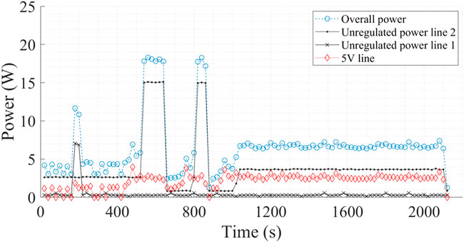
FIGURE 11. Power consumption of KITSUNE during downlink of a single JPG image (second pass).
Furthermore, the final pass was to show the scenario of downlinking the PNG image data from the C-band flash memory. The short peak at 39 s was due to the uplink command via UHF communication (Figure 12). The total energy consumed for the 512-s mission was 2.33 Wh within the KITSUNE power generation. Ultimately, the three passes verified the operation of the KITSUNE imaging mission, which is useful for mission planning in space.
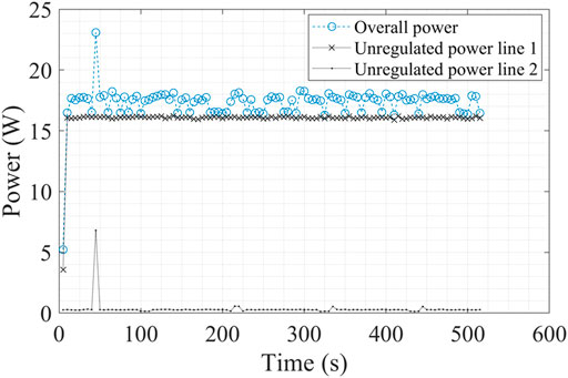
FIGURE 12. Power consumption of KITSUNE during the downlink of a single PNG image (third pass).
5 Preliminary on-orbit operational result
The KITSUNE satellite is currently in the process of completing the initial phase of operation. The imaging mission has been executed several times with several thumbnail data downloaded, as shown in Figure 13. However, to date, only one full JPG image has been retrieved through C-band communications, while the rest is a work in progress to be completed. It took a longer time to verify the main mission than expected because of extra initial time spent in completing the on-orbit power profile of operation and stabilizing the ADCS system to achieve high accuracy of target and nadir pointing modes, particularly for the imaging mission and pointing of the C-band patch antenna for downlink purposes. The metadata of the image captured (Figure 13A) is as follows:
1) Image ID: 28.
2) Date and time captured: 10 May 2022, at 07:18 a.m. (JST).
3) Location: Hubei, China.
4) JPG image size: 2.22 MB.
5) Exposure time: 256 µsec?
6) Gain: 22.0 dB.
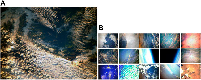
FIGURE 13. KITSUNE flight images (A) full jpg and (B) thumbnails.
The telemetry data was being regularly downloaded to monitor the health of the CubeSat as well as the temperature readings, as summarized in Table 2. The temperature sensors on the solar panels were installed inside the satellite, which means that the readings shown were not as severe as those for the outer surface of the satellite. The temperatures of the external solar cells were also analyzed and compared and most of the readings were within the ranges expected by the thermal model design and observed in TVT. However, the maximum temperature reading on the -X panel was higher than expected by the model, due to the maximum satellite beta angle, about 70.0°, and the different attitude profile of the CubeSat, which was in tumbling mode at the time. In addition, the temperature readings of the lenses during the imaging mission (image 28) at a beta angle of 61.3° are also included in Table 2. The lens (outermost) did not meet the best margin for optimal focus, so more imaging mission execution should be conducted to verify the imaging payload.
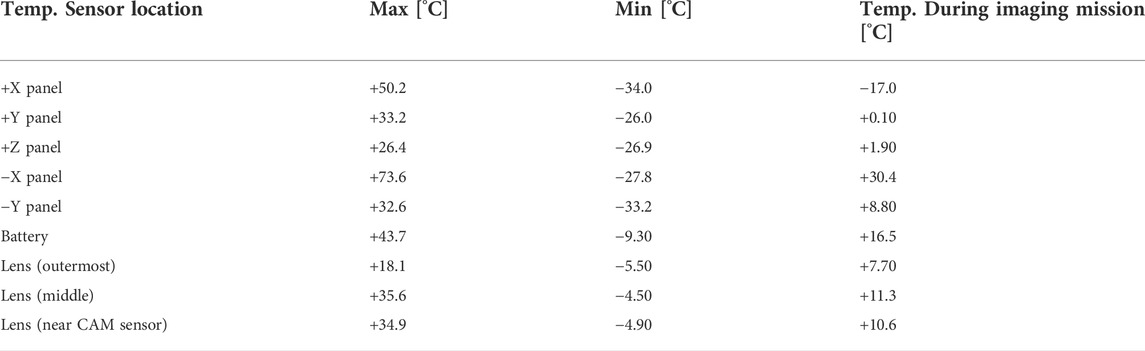
TABLE 2. On-orbit temperature readings: maximum, minimum, and during mission.
Furthermore, telemetry data of power consumption during the imaging mission was also collected and analyzed. Each time the main mission ran, the 5-V (for CCB) and 12-V (CAM sensor) power lines were turned on, which could be compared to the LDOT result. The total energies consumed for the mission on-orbit and LDOT were 0.89 and 0.82 Wh, respectively. The 8.5% difference can be attributed to the difference in temperature between harsh space weather and the room condition. The CPU of the RPi CM3+ could reduce its performance by decreasing the clock frequency at high temperatures. Therefore, the RPi CM3+ took longer to capture photos interfacing with the CAM sensor. Nevertheless, the increment of energy consumption was not critical, and did not affect the success of the imaging mission.
The KITSUNE CubeSat still has several important tasks to complete to fulfil the main mission requirements, mainly verifying the 5-m-resolution image class for extra success criteria. Firstly, the ADCS should be able to stabilize the CubeSat constantly in order to capture the photos in steady nadir and target modes. The current angular speed of KITSUNE is being passively reduced while the ADCS module is undergoing optimal calibration. Secondly, the lens temperature sensors on the camera lens are located at three different positions; however, the sensor on the lens (outermost) is not functioning well. The most likely reason is that the sensor cable has a short-circuit with the grounded structure due to not being properly installed on the camera lens. The other two temperature sensors could be used as backups by analyzing the lens variation difference. Finally, the lens heater is not yet being tested on-orbit because the lens temperature readings were above the target temperature during camera operation. The ideal time to turn on the lens heater is during lower beta angle conditions, which could be tested in the coming months.
6 Discussion
Several studies have been conducted to test the camera payload in a radiative environment. For instance, Piqueras et al. (2012) tested a custom-designed CMOS sensor for the Polarimetric and Helioseismic Imager (PHI) to a TID of 1,500 Gy. The total radiation dose was considerably high due to the Solar Orbiter mission, which resulted in a radiation tolerance up to 750 Gy only from the TID test. Another study was carried out by Coronetti et al. (2019) to test Xilinx Zynq 7,000 SoC integrated with a 3Dplus CMOS camera in a radiative environment. The result showed that the SoC fault led to several reboots when exposed to 230 Gy. Overall, both studies used CMOS sensors as the DUT, resulting in degradation as well as dark noise visible on the image captured. Nevertheless, KITSUNE RPi CM3+ was only tested for TID without a CAM sensor, due to the mission design time of fewer than two years and limited sensor availability. The on-orbit photos show no signs of degradation on the sensor after more than three months of operation.
A lengthy lens with a narrow field of view attached to the CAM sensor could cause possible damage when the payload directly faces the Sun for some time. Our curiosity regarding to this led to a Sun simulator test, which simulated the condition of CubeSat ADCS failure and eventually exposing the sensor to direct sunlight for a long period depending on the satellite attitude and rotation speed. However, the results in this study could not be compared with those of others, particularly with regard to on-ground testing and on-orbit results since no published results were found in literature. In KITSUNE, even though the ADCS is currently in process of stabilizing, no significant effect was observed from the acquired images, which matched the results from the Sun simulator on-ground test.
The standard environment tests that have been carried out for verifying the satellite systems and missions are TVT and VT. Several references could be efficiently obtained to cross-check the setting definition (Antti, 2013; Smith et al., 2018; Cho et al., 2019; Jallad et al., 2019; Kranner and Kuhnert, 2020; Morgan et al., 2021). Different CubeSat projects have used distinct parameters for the environmental tests, depending on the launch orbit and vehicle. For instance, in the LEO environment, almost all CubeSats use a similar temperature range for the TVT between -20.0 and +60.0°C. Nonetheless, in the KITSUNE TVT, the temperature was set between -15.0 and +60.0°C, based on the on-orbit data from the previous BIRDS CubeSats projects. Therefore, the test parameters could certainly be decided based on experiences with developing CubeSats at a similar orbit.
The critical points for the camera payload are the fragile optics and the component inside the sensor, which are highly affected by vibrations or shocks from the launch. In this study, the durability of the camera lens was tested several times at the unit level of the VT with a high value of random vibration QT (13.0 Grms) and sine burst (23.0 G). Even though the VT setting parameter of the study by HiREV payload (Cho et al., 2019) was higher than that for KITSUNE (14.1 G of random QT) based on the Innovative Space Logistics (ISL) data, no damage was noticed in their study. The main reason could be the different type of lens configuration used and the shorter length. The KITSUNE imaging payload consists of about 2 U volume of a composite lens with multiple discrete lenses stacked inside, yet the custom-made lens design was significantly improved during the development process. Besides that, the Aalto-1 3 U CubeSat was tested for 14.1 G of random vibration, resulting in broken bonding wires on the payload during the first VT, which was eventually solved by redesigning it in the second VT (Antti, 2013). The KITSUNE CAM sensor also witnessed similar issues during the EM, where a component came loose after the unit level test. Thus, it is recommended that a custom-made or commercial off-the-shelf (COTS) imaging payload be tested before observing any outcome problems.
On top of that, image quality measurement is considerably important for the functionality test of the camera payload. Several resolution-test target designs are available on the market, such as the 1951 USAF target, the sector star target, and the high-frequency NBS 1963A target. For instance, Cho et al. (2019) measured the image quality captured by the HiREV payload using the MIRA USAF 1951 pattern, resulting in modulation transfer function (MTF) analysis. In the KITSUNE payload, the sector star target lens was used with the collimator lens and was analyzed using the normalized focus measured operator. Both techniques could measure the image quality depending on the availability of the tools. In this study, the image captured was analyzed using Matlab software with a freely available script that could contribute significantly accurate results (Pertuz et al., 2013).
7 Conclusion
In this study, the space environment and functionality tests of the KITSUNE imaging mission were thoroughly discussed. Total ionization dose radiation, Sun simulator, thermal vacuum, vibration, and long duration operational tests were conducted on payload units along with satellite system levels tests. The test parameters were defined based on the thermal model design and on-orbit data from the previous CubeSat projects. In addition, KITSUNE satellite is the first 6U CubeSat developed and launched by Kyutech that is equipped with a high-resolution imaging payload and thermal system. The on-ground space environment tests showed that the mission was well-executed with several considerations that should be highlighted: 1) RPi CM3+ should not turn on continuously due to potential single event latch-up events, 2) the lens protector is not required as the CAM sensor could recover after facing toward the Sun, 3) the lens focal length could be modified due to various temperature and vacuum conditions, and 4) the lens and internal components of the camera sensor could be affected during launch, which could change the focus conditions. Meanwhile, the KITSUNE FM was tested extensively in a clean room with reliable mission execution. Currently, on-orbit data is continuously being collected in order to clearly understand the behavior of CubeSats in harsh space environments, particularly during an imaging mission. Moreover, the current active solar activities and space weather events could also influence the success of the KITSUNE mission by affecting the payload electronics or the bus system.
Based on the on-orbit data and on-ground tests, several improvements have been recognized for the test design and acquiring focused images on the CubeSat platform. Instead of integrating an active heater on the lens, researchers could utilize an onboard cooling mechanism, for example, thermoelectric cooling, which could be useful in the case of higher beta angles. The lens in the current design can be cooled passively; however, it could take up to two weeks to achieve the target temperature for the imaging mission based on KITSUNE beta angle cycles. Moreover, the ADCS subsystem should be tested vigorously with the imaging payload to imitate the behavior in space. Therefore, three subsystems are defined as critical to achieve the outstanding imaging mission as ADCS, COM and thermal control. A new iteration with stability improvements to the KITSUNE CubeSat with high-speed communication will likely be implemented for future projects.
Data availability statement
The raw data supporting the conclusion of this article will be made available by the authors, without undue reservation.
Author contributions
All authors listed have made a substantial, direct, and intellectual contribution to the work and approved it for publication
Funding
The work described in this paper has been supported by the Ministry of Economy, Trade and Industry (Japan), especially the 2U main bus systems, C-band, and camera payload. Part of the SPATIUM-II mission development was supported by the Ministry of Education, Culture, Sports, Science and Technology (Japan) Coordination Funds for Promoting AeroSpace Utilization, Grant No. JP000959.
Acknowledgments
The work described in this paper is supported by KITSUNE members who are not listed as authors. The team contributions are significantly important to the successful KITSUNE project. In addition, the authors would like to acknowledge the support of Prof. Mohamad Tariqul Islam on the C-band patch antennas.
Conflict of interest
Author AM was employed by the company Antarikchya Pratisthan Nepal. Authors KN and YF were employed by the company Harada Seiki Co., Ltd. Author KK was employed by the company Addnics Corp.
The remaining authors declare that the research was conducted in the absence of any commercial or financial relationships that could be construed as a potential conflict of interest.
Publisher’s note
All claims expressed in this article are solely those of the authors and do not necessarily represent those of their affiliated organizations, or those of the publisher, the editors and the reviewers. Any product that may be evaluated in this article, or claim that may be made by its manufacturer, is not guaranteed or endorsed by the publisher.
Footnotes
1https://www.nanosats.eu/sat/sirion. Last retrieved on 10 June 2022
2https://www.nanosats.eu/sat/el-camino-real. Last retrieved on 10 June 2022
3https://www.nanosats.eu/sat/palisade. Last retrieved on 10 June 2022
4https://brycetech.com/reports/report-documents/Bryce_Smallsats_2022.pdf. Last retrieved on 10 June 2022
References
Antti, N. (2013). Validation of aalto-1 spectral imager technology to space environment. Available at: https://aaltodoc.aalto.fi/bitstream/handle/123456789/%0A10451/master_Näsilä_Antti_2013.pdf?sequence=1 (Accessed 7 June 2022).
Azami, M. H. Bin, Orger, N. C., Schulz, V. H., Oshiro, T., and Cho, M. (2022). Earth observation mission of a 6U CubeSat with a 5-meter resolution for wildfire image classification using convolution neural network approach. Remote Sens. (Basel). 14, 1874. doi:10.3390/rs14081874
Azami, M. H., Maeda, G., Faure, P., Yamauchi, T., Kim, S., Masui, H., et al. (2019). BIRDS-2: A constellation of joint global multi-nation 1U CubeSats. J. Phys. Conf. Ser. 1152, 012008. doi:10.1088/1742-6596/1152/1/012008
Blackwell, W. J., Allan, G., Allen, G., Burianek, D., Busse, F., Elliott, D., et al. (2014). “Microwave radiometer technology acceleration mission (MiRaTA): Advancing weather remote sensing with nanosatellites,” in 28th Annual AIAA/USU Conference on Small Satellites, Utah. Available at: https://digitalcommons.usu.edu/smallsat/2014/Poster/7/.
Bouwmeester, J., Menicucci, A., and Gill, E. K. A. (2022). Improving CubeSat reliability: Subsystem redundancy or improved testing? Reliab. Eng. Syst. Saf. 220, 108288. doi:10.1016/j.ress.2021.108288
Chirayath, V., and Li, A. (2019). Next-generation optical sensing Technologies for exploring ocean worlds—NASA FluidCam, MiDAR, and NeMO-net. Front. Mar. Sci. 6, 521. doi:10.3389/fmars.2019.00521
Cho, D.-H., Choi, W.-S., Kim, M.-K., Kim, J.-H., Sim, E., and Kim, H.-D. (2019). High-resolution image and video CubeSat (HiREV): Development of space technology test platform using a low-cost CubeSat platform. Int. J. Aerosp. Eng. 2019, 1–17. doi:10.1155/2019/8916416
Cooley, S., Smith, L., Stepan, L., and Mascaro, J. (2017). Tracking dynamic northern surface water changes with high-frequency Planet CubeSat imagery. Remote Sens. (Basel). 9, 1306. doi:10.3390/rs9121306
Coronetti, A., Manni, F., Mekki, J., Dangla, D., Virmontois, C., Kerboub, N., et al. (2019). “Mixed-field radiation qualification of a COTS space on-board computer along with its CMOS camera payload,” in 2019 19th European Conference on Radiation and Its Effects on Components and Systems (RADECS) (Montpellier: IEEE), 1–8. doi:10.1109/RADECS47380.2019.9745699
Devaraj, K., Kingsbury, R., Ligon, M., Breu, J., Vittaldev, V., and Klofas, B. (2017). “Dove high speed downlink system,” in Annual AIAA/USU Conference on Small Satellites, Utah. SSC17–VII–02. Available at: http://digitalcommons.usu.edu/cgi/viewcontent.cgi?article=3797&context=smallsat.
Douglas, E. S., Allan, G., Morgan, R., Holden, B. G., Gubner, J., Haughwout, C., et al. (2021). Small mirrors for small satellites: Design of the deformable mirror demonstration mission CubeSat (DeMi) payload. Front. Astron. Space Sci. 8, 1–10. doi:10.3389/fspas.2021.676281
Houborg, R., and McCabe, M. (2016). High-resolution ndvi from planet’s constellation of Earth observing nano-satellites: A new data source for precision agriculture. Remote Sens. (Basel). 8, 768. doi:10.3390/rs8090768
Idzikowska, T. (2017). European standardization for the management of space-related projects. Sci. J. Silesian Univ. Technol. Ser. Transp. 95, 55–65. doi:10.20858/sjsutst.2017.95.6
Jallad, A. H., Marpu, P., Aziz, Z. A., Al Marar, A., and Awad, M. (2019). MeznSat-A 3U CubeSat for monitoring greenhouse gases using short wave infra-red spectrometry: Mission concept and analysis. Aerospace 6, 118. doi:10.3390/aerospace6110118
Khanal, S., Kc, K., Fulton, J. P., Shearer, S., and Ozkan, E. (2020). Remote sensing in agriculture—accomplishments, limitations, and opportunities. Remote Sens. (Basel). 12, 3783. doi:10.3390/rs12223783
Kim, S., Yamauchi, T., Masui, H., and Cho, M. (2021). BIRDS BUS: A standard CubeSat BUS for an annual educational satellite project. JoSS 10, 1015–1034. Available at: www.jossonline.com.
Kishimoto, M., Orger, N. C., Elmegharbel, H. A., Dayarathna, T., Lepcha, P., Yamauchi, T., et al. (2021). “On-orbit observation of total Electron content in the ionosphere by UHF ranging signal from the ground,” in Proceedings of the international astronautical congress (Dubai: IAC), 1–7.
Kranner, M. S., and Kuhnert, K. D. (2020). “Space qualification of an embedded hardware system for multi-sensor-fusion,” in 2020 6th Int. Conf. Mechatronics Robot. Eng. (Barcelona: ICMRE), 78–86. doi:10.1109/ICMRE49073.2020.9065092
Mas, J.-F., Lemoine-Rodríguez, R., González-López, R., López-Sánchez, J., Piña-Garduño, A., and Herrera-Flores, E. (2017). Land use/land cover change detection combining automatic processing and visual interpretation. Eur. J. Remote Sens. 50, 626–635. doi:10.1080/22797254.2017.1387505
Morgan, R., Douglas, E., Allan, G., do Vale Pereira, P., Gubner, J., Haughwout, C., et al. (2021). Optical calibration and first light for the deformable mirror demonstration mission CubeSat (DeMi). J. Astron. Telesc. Instrum. Syst. 7, 1–20. doi:10.1117/1.JATIS.7.2.024002
Okada, M., Yamamoto, S., and Mukai, T. (2009). Systems engineering enhancement initiative in JAXA. Trans. JSASS. Space Tech. Jpn. 7, 1. doi:10.2322/tstj.7.Tt_1
Pertuz, S., Puig, D., and Garcia, M. A. (2013). Analysis of focus measure operators for shape-from-focus. Pattern Recognit. DAGM. 46, 1415–1432. doi:10.1016/j.patcog.2012.11.011
Piqueras, J., Heerlein, K., Werner, S., Enge, R., Schühle, U., Woch, J., et al. (2012). “CMOS sensor and camera for the PHI instrument on board solar orbiter: Evaluation of the radiation tolerance,” in High energy, optical, and infrared detectors for astronomy V. Editors A. D. Holland, and J. W. Beletic (Amsterdam: SPIE), 845314. doi:10.1117/12.925403
Poghosyan, A., and Golkar, A. (2017). CubeSat evolution: Analyzing CubeSat capabilities for conducting science missions. Prog. Aerosp. Sci. 88, 59–83. doi:10.1016/j.paerosci.2016.11.002
Pradhan, K. K., and Cho, M. (2020). Shortening of delivery time for university-class lean satellites. J. Small Satell. 9, 881. Available at: www.jossonline.com.
Salguero, J., Li, J., Farahmand, A., and Reager, J. T. (2020). Wildfire trend analysis over the contiguous United States using remote sensing observations. Remote Sens. (Basel). 12, 2565. doi:10.3390/rs12162565
Slater, W. S., Tiwari, N. P., Lovelly, T. M., and Mee, J. K. (2020). “Total ionizing dose radiation testing of NVIDIA Jetson Nano GPUs,” in 2020 IEEE High Performance Extreme Computing Conference (HPEC) (Waltham: IEEE), 1. –3. doi:10.1109/HPEC43674.2020.9286222
Smith, M. W., Donner, A., Knapp, M., Pong, C. M., Smith, C., Luu, J., et al. (2018). “On-orbit results and lessons learned from the ASTERIA space telescope mission,” in 32nd Annual AIAA/USU Conference on Small Satellites, Utah. SSC18-I–08. Available at: https://digitalcommons.usu.edu/cgi/viewcontent.cgi?article=4067&context=smallsat.
Toth, C., and Jóźków, G. (2016). Remote sensing platforms and sensors: A survey. ISPRS J. Photogramm. Remote Sens. 115, 22–36. doi:10.1016/j.isprsjprs.2015.10.004
Toumbas, G. (2018). Raspberry Pi radiation experiment. Available at: https://www.electronicwings.com/raspberry-pi/raspberry-pi-gpio-access (Accessed 7 June 2022).
Keywords: space environmental tests, lens, image focus measure, CubeSats, imaging payload
Citation: Azami MHB, Orger NC, Schulz VH, Oshiro T, Alarcon JRC, Maskey A, Nakayama K, Fukuda Y, Kojima K, Yamauchi T, Masui H and Cho M (2022) Design and environmental testing of imaging payload for a 6 U CubeSat at low Earth orbit: KITSUNE mission. Front. Space Technol. 3:1000219. doi: 10.3389/frspt.2022.1000219
Received: 21 July 2022; Accepted: 24 October 2022;
Published: 07 November 2022.
Edited by:
Ugo Lafont, European Space Research and Technology Centre (ESTEC), NetherlandsReviewed by:
Ugur Murat Leloglu, Middle East Technical University, TurkeySung Wook Paek, City University of London, United Kingdom
Copyright © 2022 Azami, Orger, Schulz, Oshiro, Alarcon, Maskey, Nakayama, Fukuda, Kojima, Yamauchi, Masui, Cho and KITSUNE Team Members. This is an open-access article distributed under the terms of the Creative Commons Attribution License (CC BY). The use, distribution or reproduction in other forums is permitted, provided the original author(s) and the copyright owner(s) are credited and that the original publication in this journal is cited, in accordance with accepted academic practice. No use, distribution or reproduction is permitted which does not comply with these terms.
*Correspondence: Muhammad Hasif Bin Azami, YXphbWkubXVoYW1tYWQtaGFzaWY5NTdAbWFpbC5reXV0ZWNoLmpw; Necmi Cihan Orger, b3JnZXIubmVjbWktY2loYW4zOTdAbWFpbC5reXV0ZWNoLmpw; Mengu Cho, Y2hvLm1lbmd1ODAxQG1haWwua3l1dGVjaC5qcA==