 Alexander Muravsky1,2*
 Anatoli Murauski2,3
- 1MTLCD Lab, Private Research Unitary Enterprise “MTLCD”, Minsk, Belarus
- 2Soil Analysis Laboratory, Ecole Paysanne de Lignerolles, Le Thieulin, France
- 3Materials and Technologies of LC Devices Laboratory, Institute of Chemistry of New Materials, National Academy of Science of Belarus, Minsk, Belarus
We selected and summarized the most important aspects of liquid crystal alignment. Alignment by the surface profile and flat surface alignment are discussed as the main factors leading to the high-quality orientation of liquid crystals. The advanced level of understanding and formulation allows linking the alignment layer properties to the molecular structure of the alignment material. The paper reviews and combines the latest knowledge about liquid crystal alignment, dwells upon the relationship between the polar and azimuthal anchoring energy, explains the major particularities regarding anchoring measurements in the case of birefringent alignment materials with truly high azimuthal anchoring energy, and observes the current trends of water-friendly alignment materials and their application in geometrical phase device fabrication.
1 Introduction
Liquid crystal (LC) alignment is the degree of freedom essential for structural design engineering of liquid crystal devices (LCDs). To some extent, due to its complexity, common knowledge about LC alignment matter is typically reduced to a “planar (PL) or vertical alignment (VA) layer achieved through certain standard treatments of commercial alignment material.” The comprehension of the knowledge about contemporary levels of LC alignment requires an advanced level of understanding of anisotropic optics, holography, liquid crystals, organic chemistry, physical chemistry, material science, theoretical physics, and electro–optical engineering. In this content, we extract and share our best practices gained through over a decade of LC alignment research. In addition, extensive data on LC alignment materials and technologies broaden the scope of theoretical possibilities and technical solutions available to scientists and engineers from the alignment material side. Thus, this paper reviews and summarizes the main aspects of LC alignment and observes its contemporary state, as well as illustrates the practical cases that introduce a wide range of possibilities given by alignment materials via this unexplored degree of freedom to liquid crystal science researchers and LC device technology developers.
2 Basics of LC alignment
2.1 Orientation interaction
First, the main aspects of liquid crystal materials are discussed. The shape of the molecular structure determines whether the material has an LC phase. The LC phase material structures with dipole moments form an electromagnetic field in the volume of the LC mixture and interact with it. In the nematic LC phase, the dipole moment,
In nematic LC order parameters, P1 = 0 and P2 = 0.4–0.8, while in ferroelectric LC order parameters, P1 ≠ 0 and P2 ≠ 0. Further on, we only consider nematic liquid crystals.
LCs also exhibit elastic orientation properties. When trying to locally change the direction of orientation of molecules, there are forces that return the molecules to their average orientation state. These properties are described by the elastic theory of liquid crystals (Frank, 1958).
In free space, LC molecules are oriented randomly. The external impact (such as the electric or magnetic field) can orient LC molecules in one direction. In the case of the external field, the influence occurs on each of the molecules, and they are all oriented in the same direction given by the field.
2.2 Surface alignment interaction
Surface LC alignment is the interaction of the liquid crystal continuum with the bounding surface, leading to the orientation of the LC director at the interface in the direction

FIGURE 1. Polar coordinates of alignment direction on the surface of the alignment film.
The anchoring energy causes the force applied to the liquid crystal media at the surface from the alignment layer, which tends to minimize the total energy of the system:
Needless to mention, the same force is applied to the alignment layer surface in the liquid crystal medium. In some rare cases, it may even cause inelastic deformation of the surface of the alignment layer, which is the failure of the alignment material. The nabla operator ∇ indicates the mathematical operation of a gradient in direction. Thus, the change in the anchoring energy makes a contribution, while the constant does not contribute to the LC alignment. The standard formulation of the anchoring energy is the Rapini–Popoular form (Barbero and Durand, 1986):
which, in polar coordinates, is the sum of polar, Ap, and azimuthal, Aa, surface anchoring energies:
where Wp and Wa are the constants of polar and azimuthal anchoring energies, respectively.
The actual surface LC direction is due to the anisotropy of its properties on the surface. Thus, if the surface of the substrate is treated to provide it with anisotropic properties, then the liquid crystal on such a surface will be oriented in one direction.
2.2.1 Alignment by the profiled surface
A simple way to add anisotropy to a surface is to create a wave-like profile. This alignment technique is widely utilized in oblique vacuum deposition, embossing, and rubbing. All these methods are based on the modification of the surface profile. The alignment effect is the result of minimizing the energy of LC elastic deformation. The liquid crystal is oriented in such a way as to reduce the size of the bulk deformations caused by the surface (Figure 2). Figure 2A shows the orientation of the LC director along the surface profile without the elastic deformation of the liquid crystal, which minimizes the LC deformation energy. Figure 2B shows the orientation of the LC director along the surface but perpendicular to the profile, which maximizes the LC deformation energy. The difference in the LC deformation energies at the profiled surface is subject to the parameters of the surface profile and is the cause of LC alignment.
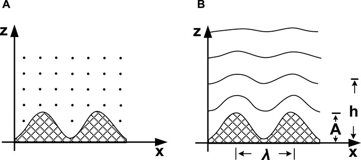
FIGURE 2. Liquid crystal orientation on the surface profile: (A) without and (B) with elastic deformations of the liquid crystal medium.
According to method of Berreman (1972), the LC alignment impact of the surface profile on the azimuthal anchoring energy coefficient is as follows:
where A is the profile height, λ is the profile pitch, and K is the elastic constant of the liquid crystal.
The Berreman method admits the infinite polar anchoring energy coefficient. However, in the case of finite polar anchoring, the formula for the azimuthal anchoring coefficient is modified (Faetti, 1987) as follows:
Considering the equation above, it is easy to conclude that azimuthal anchoring is a part of polar anchoring or Wp > Wa. Thus, in the case of weak polar LC–surface interaction, the azimuthal anchoring of the profiled surface is weak. In such a case, the coating of the surface profile with a thin layer of the polar material increases the azimuthal anchoring (Hileuskaya et al., 2023).
At the same time, for strong-anchoring (Wa > 10−5 J/m2) cases, one can measure Wa as the lower anchoring limit and vice versa, i.e., for low-anchoring cases (Wa ≤ 10−7–10–6 J/m2), one should consider Wp as the upper anchoring limit.
2.2.2 Alignment by the flat surface
The influence of the surface on the orientation of the liquid crystal is not limited to the surface profile only. There are stronger interactions that have nothing to do with surface profiling. Photoalignment is the most striking evidence of this statement. The surface profile does not change during photoalignment, while the LC alignment direction is set by the orientation of the light polarization plane when the photoalignment material surface is exposed to polarized light.
The same forces and interactions that cause the orientation of LC molecules in one direction in the volume are also strong when interacting with the alignment surface. These are the dipole–dipole interactions. If there is a layer on the surface of which the dipole moments of the molecules are oriented in one direction, then, when interacting with such a surface, the LC will be oriented in the direction specified on the surface of the alignment layer. The energy of the LC interaction with such a layer is given as follows (Murauski, 2009):
where φ is the angle between the mean directions of the dipole moments of layers a and b; μ is the dipole moment; z is the distance between layers a and b; P1 and P2 are the orientation order parameters; and С0 is the normalizing constant.
In the case of smectic LC, orientational order parameter P1 ≠ 0 should be taken into account. However, in the case of nematic LC, P1 = 0, and the formula is reduced, which allows us to derive the azimuthal anchoring energy coefficient as the factor of the squared cosine term (Muravsky et al., 2020):
where
3 Q&A of liquid crystal alignment
3.1 Classical rubbing alignment
Polyimide film is the standard LC alignment layer widely applied in LCD fabrication. After coating with the imide solution, the film undergoes high-temperature baking at typically T ≥ 180°C for >1 h for the thermal imidization process that forms linear polyimide chains. The rubbing step that follows causes inelastic shear deformation of the polyimide film, ordering the chains at the surface along the rubbing direction (Stohr and Samant, 1999). In the ideal case, it is the flat surface alignment. Since the rubbing alignment effect comes not from surface scratching but due to the surface ordering of polyimide chains formed at the hard-baking step (Figure 3), the prior high temperature is essential, while the rubbing conditions and the rubbing cloth are critical (Yamahara et al., 2007). High-temperature imidization is already a standard but a rather slow and limiting step. Can it be changed to an alternative?
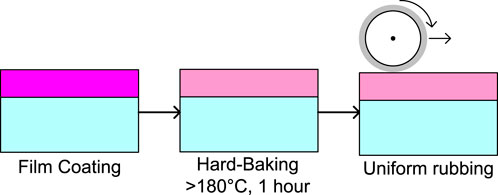
FIGURE 3. Process flow of the rubbed polyimide alignment layer.
3.2 Low-temperature alignment material
Rethinking a standard concept is always challenging. The MTLCD laboratory rethought and developed a low-temperature alignment material (LTAM) that replaced imidization with photo-crosslinking under UV light (Mahilny et al., 2009) (Figure 4).
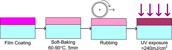
FIGURE 4. Process flow of the low-temperature alignment material (LTAM) alignment layer.
The 1%–2% solution of methacrylate polymer with photosensitive benzaldehyde groups in butyl acetate is applied for coating a thin film 20–80 nm on the substrate. Soft baking at 60°C–90°C for 5 min is performed to dry the solvent. The polymer film undergoes inelastic shear deformation of the film surface upon the standard rubbing step with cotton clothes, ordering the polymer chains along the rubbing direction. Finally, non-polarized UV-C/UV-B light exposure at wavelengths of 250–330 nm for ∼1 min is applied to induce photo-crosslinking of the side benzaldehyde groups, which fixes the spatial orientation of the polymer chains, making the polymer solvent insoluble and insensitive to rubbing. Such an alignment material does not possess absorption in the UV-A and blue-VIS spectral ranges for excellent photostability of the LC device.
Needless to mention, LTAM, originally intended for plastic substrates, has excellent chemical compatibility with a wide range of standard substrates, i.e., polyethylene terephthalate (PET), triacetyl cellulose (TAC), polycarbonate (PC), and others. The critical aspect is that common organic solvents applied for alignment layer coating, such as dimethylformamide (DMF), N-methyl-2-pyrrolidone (NMP) or even acetone, work well on glass but often fail on plastic substrates. The LTAM alignment layer was successfully applied on top of the TAC film of the internal polarizer inside 42” IPS 3D LCD (Park et al., 2014).
3.3 Planar, vertical, and pretilt gradient LTAM for liquid crystal lenses
Photo-crosslinking involves modification of the polymer properties. Can light exposure change the liquid crystal pretilt angle at the surface of the photosensitive alignment layer? In fact, the LC pretilt angle is dose-dependent in the case of the alignment layer. Polar anchoring changes upon light exposure (Bezruchenko et al., 2018). Such LTAMs, achieved through the careful designing of polymer chemistry (Bezruchenko et al., 2016), can provide gradient alignment conditions tuning from VA to PL through light exposure control. The main application of pretilt angle gradient alignment materials is the fabrication of polarization-independent liquid crystal lenses (Bezruchenko et al., 2021) and LC lens arrays (Figure 5) (Muravsky et al., 2022).
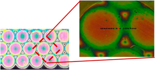
FIGURE 5. Microscopic photograph of liquid crystal (LC) lens array with the pretilt angle gradient oriented at 45° to light polarization observed in between crossed polarizers.
3.4 Holographic embossing alignment for the roll-to-roll process
High polar interaction causes planar liquid crystal alignment with a low pretilt angle, but how do we create and control the azimuthal angle distribution? Classical rubbing causes uniform alignment on the solid substrate, but it is not suitable for the azimuthal pattern on plastic substrates. Can the formation of a profiled surface cause a patterned azimuthal angle at the surface of the LTAM alignment layer?
The holographic embossing process, used in relief-phase hologram manufacturing, was applied for the formation of a patterned profiled surface of a special polymer layer via embossing of a holographic matrix with predetermined directions of diffraction gratings (Mikulich et al., 2019). Such holographic embossing alignment allows roll-to-roll fabrication of patterned quarter- and half-wave retarders from polymerizable liquid crystals on TAC, PET, and PC substrates (Moiseenko et al., 2019) at a roll speed of 20 m/min. The holographic embossing alignment has the highest process temperature of 70°C, which achieves strong azimuthal anchoring over 10−5 J/m2 and is suitable for q-plates and vortex retarder array fabrication (Figure 6).
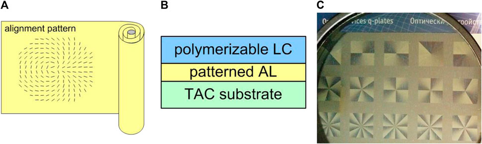
FIGURE 6. (A) Scheme of roll with the holographic alignment pattern, (B) structure of the polymerizable LC device on the triacetyl cellulose (TAC) substrate, and (C) photograph of the LC photonic device array with azimuthal patterns for different topological charges observed on the aluminum reflector through the linear polarizer.
3.5 High-anchoring photoalignment materials for LC photonics
Flat surface alignment is the opposite of profiled surface alignment. Can the flat surface provide a patterned azimuthal alignment of liquid crystal? Photoalignment provides a direct positive answer verified in the experiment. The photoalignment process (Figure 7) comprises film coating, baking, and polarized light exposure. The latter induces anisotropic changes in the film that form the azimuthal LC alignment direction on the flat surface of the photoalignment material (Chigrinov et al., 2008).

FIGURE 7. Process flow of the photoalignment layer.
Flat optics and LC photonics based on the liquid crystal-mediated geometrical phase are one of the most advanced and promising applications of contemporary photoalignment technology (Chen et al., 2020). Successful LC device fabrication requires photoalignment materials with azimuthal anchoring energy constant Wa >10−4 J/cm2, which is equivalent to PI rubbing used in LC displays. High azimuthal anchoring is needed to minimize deviations in the azimuthal plane of the LC optical axis from the LC alignment direction given by the alignment layer. For the flat surface case, it requires alignment materials with high dipole moments, like AtA-0042 with
3.6 Azimuthal anchoring energy measurement
The largest deviation in the azimuthal plane of achiral nematic LC is obtained in a 90-twist nematic (TN) cell, when the azimuthal orientations given by the alignment layer on top and bottom substrates are orthogonal, giving cell twist angle
What is the principle of azimuthal anchoring energy measurement? Torque balance is the basic principle, and it is achieved when the energies of LC twist deformation and azimuthal anchoring at both substrates are equal:
where
This assumption is not valid for an optically anisotropic alignment layer with retardation
where
Thus, the alignment layer birefringence,
3.7 Photoinduced hole-dipole photoalignment mechanism
Azo dyes are one of the most efficient LC photoalignment materials (Chigrinov et al., 2005) that have already been researched for over 2 decades. What experimental facts ground contemporary knowledge about the high-anchoring azo-dye photoalignment? A large set of chemical and physical experiments have been performed to clarify the role of different groups of the structure of azo-dye molecules, optimizing LC photoalignment properties and revealing the physics behind it.
Thus, it is established that when the intermolecular hydrogen bond blocks the cis–trans isomerization of the azo group, the photoalignment properties vanish (Mikulich V. S. et al., 2015). Temperature is an alternative way to block the cis–trans isomerization. It is established that the azo-dye photoalignment layer photosensitivity completely disappears at 103°C and reappears at room temperature (Mikulich et al., 2016a). At the same time, the temperature neither affects the ability of the dye layer to orient liquid crystals nor changes the alignment direction as photoalignment azo-dye molecules are the salts of alkali metals that form intermolecular coordination bonds (Muravsky, 2009). The bonding energy of the coordination bonds,
where
Since the azo-dye molecules of the photoalignment layer are bonded by coordination bonds, the photoalignment properties depend on the kind of alkali metals (lithium [Li], sodium [Na], potassium [K], rubidium [Rb], or cesium [Cs]), and as verified in the experiment, the K-salts are preferable (Mikulich et al., 2014). According to the diffusion model of photoaligning in azo-dye layers (Chigrinov et al., 2004), the dye molecules became oriented perpendicular to the polarization of light exposure, increasing the dye-order parameter,
However, investigating the dependences of photoinduced
3.8 Water-friendly photoalignment materials
The popular photoalignment azo-dye Brilliant Yellow (BY) is air humidity-dependent (Wang et al., 2017). Why does the water sensitivity of azo-dye happen? The dye layer is coated with the solution of the dry dimethylformamide (DMF) solvent. However, BY photoalignment properties fail if the layer comes into contacts with water or is exposed to humid air. The major troublemaker is sodium sulfonate groups of the dye structure, i.e., RSO3Na. Due to this group, the dye layer absorbs water from the air, forming crystal hydrates and losing its photosensitivity. In fact, crystal hydrate formation is a common problem of azo dyes with the sulfonate group. However, are there water-friendly photoalignment azo-dyes that are not afraid of water? FbF dye is the first type of water-friendly photoalignment material (Mikulich V. et al., 2015), which yields film that is completely inert to direct water contact and can be rinsed with H2O.
The recent trends in LC photoalignment follow sustainable development for “GreenLab” with the main idea of applying processes that require harmless solvents and generate less pollution. DMF is the standard solvent for azo-dye photoalignment materials. Can the DMF solvent be changed to water? Rethinking the dye structure, it is possible to refuse using DMF solvent and coat films with water. AtA-2522/AbA-2522 dyes are the second type of water-friendly photoalignment materials that can be coated in a fully functional photoalignment layer from H2O solution, which provides excellent chemical compatibility. Thus, the AtA-2522 photoalignment layer can be directly coated on top of the polymerizable LC layer for multilayer structure fabrication with advanced properties, i.e., achromatic polymerizable liquid crystal retarder (Muravsky et al., 2023).
4 Conclusion
The theory of liquid crystal alignment by flat and profiled surfaces is reviewed, focusing on the material treatment of different LC alignment techniques. The examples of rubbing, embossing, and photoalignment practices are considered and analyzed. The importance of alignment layer birefringence is revealed, and its role in the optical method for azimuthal anchoring energy measurement is underlined. The recent LC alignment trend of water-friendly photoalignment materials following sustainability for “GreenLab” is revealed.
This mini-review examines, in the most complete way, the materials and methods of their processing for the high-anchoring orientation of liquid crystals. Methods of sputtering, etching, ion etching, and other methods of surface profile alignment do not yield high anchoring and were not considered.
Author contributions
AlM: conceptualization, data curation, formal analysis, investigation, methodology, project administration, resources, supervision, validation, visualization, writing–original draft, and writing–review and editing. AnM: conceptualization, investigation, methodology, software, validation, and writing–review and editing.
Funding
The author(s) declare that financial support was received for the research, authorship, and/or publication of this article. The authors acknowledge support from the European Union grant contract ENI/2021/423-841-0035.
Conflict of interest
Author AlM was employed by Private Research Unitary Enterprise “MTLCD.”
The remaining author declares that the research was conducted in the absence of any commercial or financial relationships that could be construed as a potential conflict of interest.
The author(s) declared that they were an editorial board member of Frontiers, at the time of submission. This had no impact on the peer review process and the final decision.
Publisher’s note
All claims expressed in this article are solely those of the authors and do not necessarily represent those of their affiliated organizations, or those of the publisher, the editors, and the reviewers. Any product that may be evaluated in this article, or claim that may be made by its manufacturer, is not guaranteed or endorsed by the publisher.
References
Barbero, G., and Durand, G. (1986). On the validity of the Rapini-Papoular surface anchoring energy form in nematic liquid crystals. J. de Physique 47 (12), 2129–2134. doi:10.1051/jphys:0198600470120212900
Berreman, D. W. (1972). Solid surface shape and the alignment of an adjacent nematic liquid crystal. Phys. Rev. Lett. 28 (26), 1683–1686. doi:10.1103/PhysRevLett.28.1683
Bezruchenko, V., Muravsky, A., Murauski, A., Stankevich, A., and Mahilny, U. (2018). Alignment materials with controllable anchoring energy. J. Soc. Inf. Displ. 26, 561–566. doi:10.1002/jsid.675
Bezruchenko, V. S., Muravsky, A. A., Murauski, A. A., Stankevich, A. I., and Mahilny, U. V. (2016). Tunable liquid crystal lens based on pretilt angle gradient alignment. Mol. Cryst. Liq. Cryst. 626 (1), 222–228. doi:10.1080/15421406.2015.1106890
Bezruchenko, V. S., Muravsky, A. A., Murauski, A. A., Stankevich, A. I., and Mahilny, U. V. (2021). Gradient pretilt angle alignment materials with different photosensitivity for tunable polarization-independent self-aligned liquid crystal lens. J. Soc. Inf. Displ 29, 825–832. doi:10.1002/jsid.990
Chen, P., Wei, B.-Y., Hu, W., and Lu, Y.-Q. (2020). Liquid-crystal-mediated geometric phase: from transmissive to broadband reflective planar optics. Adv. Mater. 32, 1903665. doi:10.1002/adma.201903665
Chigrinov, V., Kwok, H.-S., Takada, H., and Takatsu, H. (2005). Photo aligning by azo dyes: physics and applications. Liq. Cryst. Today 14, 1–15. doi:10.1080/14645180600617908
Chigrinov, V., Pikin, S., Verevochnikov, A., Kozenkov, V., Khazimullin, M., Ho, J., et al. (2004). Diffusion model of photoaligning in azo-dye layers. Phys. Rev. E 69, 061713. doi:10.1103/PhysRevE.69.061713
Chigrinov, V. G., Kozenkov, V. M., and Kwok, H.-S. (2008). Photoalignment of liquid crystalline materials: physics and applications. Chichester: John Wiley & Sons. doi:10.1002/9780470751800
Faetti, S. (1987). Azimuthal anchoring energy of a nematic liquid crystal at a grooved interface. Phys. Rev. A 36, 408–410. doi:10.1103/PhysRevA.36.408
Frank, F. C. (1958). I. Liquid crystals. On the theory of liquid crystals. Discuss. Faraday Soc. 25, 19–28. doi:10.1039/DF9582500019
Hileuskaya, K., Kakasi, B., Kulikouskaya, V., Vonderviszt, F., Nikolaichuk, V., Dubatouka, K., et al. (2023). Contact guidance of mesenchymal stem cells by flagellin-modified substrates: aspects of cell-surface interaction from the point of view of liquid crystal theory. Colloids Surfaces A Physicochem. Eng. Aspects 663, 131113. doi:10.1016/j.colsurfa.2023.131113
Konovalov, V. A., Muravski, A. A., Yakovenko, S. Y., and Pelzl, J. (2000). P-25: an accurate spectral method for measuring twist angle of twisted cells with rubbed and grooved surfaces. SID Symp.Dig.Tech.Pap. 31, 620–623. doi:10.1889/1.1833023
Mahilny, U. V., Stankevich, A. I., Muravsky, A. A., and Murauski, A. A. (2009). Novel polymer as liquid crystal alignment material for plastic substrates. J. Phys. D. Appl.Phys. 42, 075303. doi:10.1088/0022-3727/42/7/075303
Mikulich, V., Boboreko, A., Moiseenko, P., and Shevtsov, V. (2019). “Production of retardation film with pixel structure” in International conference “EuroDisplay” (Belarus: Minsk), 16-20, 60.
Mikulich, V., Murauski, A., Muravsky, A., Agabekov, V., and Bezruchenko, V. (2015b). Waterproof material for liquid crystals photoalignment based on azo dyes. J. Soc. Info. Displ. 22, 199–203. doi:10.1002/jsid.238
Mikulich, V. S., Murauski, A. A., Muravsky, A. A., and Agabekov, V. E. (2016a). Effect of temperature on the photoalignment of azo dyes in thin films. Russ. J.Phys.Chem. 90, 675–682. doi:10.1134/S0036024416030262
Mikulich, V. S., Murauski, An.A., Muravsky, Al.A., and Agabekov, V. E. (2016b). Influence of methyl substituents on azo-dye photoalignment in thin films. J. Appl. Spectrosc. 83, 115–120. doi:10.1007/s10812-016-0252-y
Mikulich, V. S., Muravsky, A. A., Murauski, A. A., and Agabekov, V. E. (2015a). Effect of cis/trans-isomerisation on photoalignment of azo dyes. Russ. J. Gen. Chem. 85, 571–576. doi:10.1134/S107036321503007X
Mikulich, V. S., Muravsky, A. A., Murauski, A. A., Kukhta, I. N., Agabekov, V. E., and Altamimi, R. (2014). Photoalignment dynamics of azo dyes series with different coordination metals. J. Soc. Inf. Displ. 1, 29–34. doi:10.1002/jsid.217
Moiseenko, P., Boboreko, A., Shevtsov, V., Muravsky, A., and Murauski, A. (2019).Mass production of patterned polymerizable liquid crystal devices by roll-to-roll technology, International conference “EuroDisplay”. Belarus: Minsk, 70.
Murauski, A. (2009). Surface and liquid crystal interlayer interactions: characterizations and applications. China: VDM Verlag.
Muravsky, A., Bezruchenko, V., Murauski, A., and Mahilny, U. (2022). 54.3: invited paper: surface control of LC alignment for creation of liquid crystal lenses arrays. SID Sym. Dig.Tech.Pap. 53 (S1), 538–540. doi:10.1002/sdtp.16015
Muravsky, A., and Murauski, A. (2021). 40.3: effect of birefringent alignment layer on azimuthal anchoring energy measurement. SID Int. Symp. Dig. Tech. Pap. 52 (S2), 497–499. doi:10.1002/sdtp.15176
Muravsky, A. A., Murauski, A. A., and Kukhta, I. N. (2020). Photoinduced hole dipoles’ mechanism of liquid crystal photoalignment. Appl. Opt. 59, 5102–5107. doi:10.1364/AO.392068
Muravsky, A. A., Murauski, A. A., Kukhta, I. N., and Yakovleva, A. S. (2021). High anchoring photoalignment material based on new photo-induced hole dipoles' mechanism. J. Soc. Inf. Displ. 29, 833–839. doi:10.1002/jsid.1020
Muravsky, A. A., Murauski, A. A., and Yakovleva, A. S. (2023). 47.1: green technology of photoalignment layer coating from H2O solution for achromatic polymerizable liquid crystal retarder. SID Sym. Dig.Tech.Pap. 54 (S1), 333–335. doi:10.1002/sdtp.16297
Park, J., Lee, D., Kim, S., Yun, M., Jeong, W., Lim, K., et al. (2014). “Cell laminated polarizer on patterned retarder 3D display with low temperature alignment,” in Material, 21st international display workshop (IDW’14) (Japan: Niigata), 3–5.
Stohr, J., and Samant, M. G. (1999). Liquid crystal alignment by rubbed polymer surfaces: a microscopic bond orientation model. J. Electron. Spect. Rel. Phen. 98–99, 189–207. doi:10.1016/S0368-2048(98)00286-2
Wang, J., McGinty, C., West, J., Bryant, D., Finnemeyer, V., Reich, R., et al. (2017). Effects of humidity and surface on photoalignment of brilliant yellow. Liq. Cryst. 44 (5), 863–872. doi:10.1080/02678292.2016.1247479
Keywords: liquid crystal alignment, photoalignment, anchoring energy, liquid crystals, liquid crystal device technology
Citation: Muravsky A and Murauski A (2024) Q&A of liquid crystal alignment: theory and practice. Front. Soft Matter 4:1382925. doi: 10.3389/frsfm.2024.1382925
Received: 06 February 2024; Accepted: 01 March 2024;
Published: 18 March 2024.
Edited by:
Qi-Huo Wei, Southern University of Science and Technology, ChinaReviewed by:
Yubing Guo, Beijing Institute of Technology, ChinaCopyright © 2024 Muravsky and Murauski. This is an open-access article distributed under the terms of the Creative Commons Attribution License (CC BY). The use, distribution or reproduction in other forums is permitted, provided the original author(s) and the copyright owner(s) are credited and that the original publication in this journal is cited, in accordance with accepted academic practice. No use, distribution or reproduction is permitted which does not comply with these terms.
*Correspondence: Alexander Muravsky, YWxleGFuZGVyLm11cmF2c2t5QGdtYWlsLmNvbQ==