 Dan Pang1
 Yu Yin
- 1State Grid Changchun Power Supply Company, Changchun, China
- 2Key Laboratory of Modern Power System Simulation and Control & Renewable Energy Technology, Ministry of Education (Northeast Electric Power University), Jilin, China
Introduction: With the rise of distributed energy resources, the interconnection of distribution networks and Flexible Multi-State Switch (FMSS) has become a key technology in the construction of new distribution networks. FMSS plays a significant role in enhancing the reliability and flexibility of the system.
Methods: This paper investigates the impact of mode-switching in FMSSs on voltage shocks, current shocks, and power fluctuations in the event of a feeder fault in a multi-port flexible interconnected distribution system. Firstly, an improved state-tracking control method is proposed to effectively mitigate these impacts. Secondly, for feeder faults connected to the fixed DC bus voltage (Udc-Q) control port, a reselection method for the Udc-Q control port at the main station is introduced, aiming to select the optimal port to maintain the stability of the DC bus voltage.
Results: Simulation experiments have validated the effectiveness of the proposed control method in reducing voltage and current shocks as well as power fluctuations. Additionally, the proposed control strategy has demonstrated an enhancement in the safe and stable operation of the system under emergency fault conditions.
Discussion: The control strategy presented in this paper is capable of addressing the challenges posed by feeder faults and ensuring the stability of the DC bus voltage and reliable power supply to feeder loads, thereby enhancing the overall performance and reliability of the flexible interconnected distribution system. The research findings have been verified on the MATLAB/Simulink simulation platform.
1 Introduction
When distributed generation (DG) is widely accessed by a distribution system for its system's stability and security, a series of challenges are presented (Li et al., 2021). Each distribution network transformer is often caught in a light- and heavy-load operation state due to the uncertainty of the DG output and load casting, and the comprehensive transformer loss rises (Wei et al., 2023). When a traditional distribution system operates normally, the power of each distribution network is naturally distributed, and actively regulating the load demand is impossible. When a traditional distribution network feeder fails, relying only on the contact switch and sectional switch, the power interaction between the distribution network (Ji et al., 2019) cannot be regulated to support the load and ensure the economic operation of the distribution network transformer simultaneously.
A flexible multi-state switch (FMSS), a power electronic device that can flexibly interconnect each distribution network, can replace a traditional switch (Sarantakos et al., 2021). FMSS access to the distribution network can strengthen the ability to regulate the trend of the distribution network so that its trend distribution becomes flexible, bidirectional, continuous, and controllable (Dong et al., 2018). When the distribution network feeder fails, the intelligent distribution system can quickly detect the location and nature of the fault and cut off the faulty part in time to minimize the impact (Xiao et al., 2017). After isolating the faulted area, the FMSS can utilize the unaffected DG and distribution routes to restore power to the lost area by switching the FMSS port control mode, effectively reducing the outage time (Wang C. et al., 2022). However, the FMSS inevitably generates a transient adjustment process when switching between different operation modes. To suppress the voltage and current shocks generated during the switching process and reduce the fluctuation of the DC-side voltage and system power, a smooth switching method is needed to change the FMSS's operation state and ensure the reliability of the whole system's power supply after feeder failure.
At present, feeder failures of FMSS-containing distribution systems generally exist in two cases: power-regulated (P-Q) control ports and Udc-Q control ports connected to feeder failures. To ensure that the feeder loads do not lose power, carrying out the corresponding mode-switching action is necessary, and the switching process of different control modes has its own characteristics. When the feeder connected to the P-Q control port fails, quickly and accurately switching the port to the Droop control mode with a constant AC voltage Uac and a constant frequency f is necessary. When the feeder connected to the Udc-Q control port fails, not only is switching the port to the Droop control mode necessary, so, too, is selecting one of the remaining P-Q control ports to switch to the Udc-Q control mode.
Scholars have conducted corresponding studies on smooth switching in these two cases, respectively, and for the P-Q control port connected feeder failure, Liu and Wang (2023) proposed a control strategy to improve the traditional energy storage inverter, which reduces the power deficit, voltage fluctuation and frequency fluctuation during the switching process by adding additional power modules and additional frequency and voltage control modules. However, there is no coordinated control of the whole microgrid. Feng and Liu (2016) proposed a microgrid optimization control strategy with a composite energy storage device for switching between the grid-connected mode and the islanding mode in the microgrid. Before and after the operation mode switching, the frequency and voltage of the microgrid can be kept within the permissible range to realize smooth switching. Tian et al. (2017) proposed a smooth switching method based on a controller state that effectively reduces the system transient oscillations generated during switching. However, the redundant Proportional Integral (PI) regulator in this method also brings additional computation. Lin et al. (2021) proposed a smooth switching method based on controllers' state compensation that effectively reduces the state differences between controllers by setting appropriate reference values for the inner-loop currents and utilizing a compensation algorithm. However, due to the uncertainty of the compensation amount, setting reasonable upper and lower limits for the PI regulator makes it more complicated. Wang X. et al. (2022) proposed a smooth switching method that incorporates cooperative phase angle compensation, cooperative control switching, and pre-synchronization techniques via an FMSS. This method can quickly alleviate the impact caused by the sudden change of the initial phase angle and control mode of the FMSS at the switching instant, reduce the frequency and voltage offset during the switching process, and shorten the recovery time. The preceding method is able to suppress the impact of the switching process to a certain extent when coping with such fault conditions.
For Udc-Q control port-connected feeder faults, Wang J. et al. (2022) proposed a reciprocal control strategy for suppressing voltage fluctuations, which significantly improves the stabilization speed and suppression of DC-side voltage fluctuations under single-port faults. However, a temporary uncontrollable state of the system power occurs when a fault occurs at any port. Duan et al. (2020) and Yang et al. (2021) proposed a load-balancing regulation strategy based on virtual synchronous machine technology and a main transformer heavy-load automatic regulation strategy, respectively, which realized the balancing of feeder loads, as well as the multimode control switching operation, but accordingly, the overall structural design and the control strategy became more complicated. Liu et al. (2024) proposed a smooth switching strategy based on Linear Active Disturbance Rejection Control (LADRC), that significantly reduces the magnitude of the current command value change during the control mode switching by optimizing the design of the DC voltage outer loop and introducing a decoupled state observer and feedback of the inner-loop current command value, thus realizing a smoother switching process, lowering the DC voltage offset rate of the FMSS, and smoothing the transition of the active power at the port. For this fault location, the previously mentioned literature effectively reduces the DC-side voltage fluctuation and power fluctuation brought by the switching process, but no specific solution is given for reselecting the Udc-Q control port.
The Udc-Q control port selection condition contains the optimal operation objective operation of the system. Hu et al. (2021) thoroughly discussed the significant advantages of FMSSs in trend optimization and then constructed a distribution network operation optimization model containing FMSSs. Wang et al. (2024) proposed a flexible interconnection system optimization operation strategy, taking into full consideration the degree of load balance in the distribution area, the economic operation of the main transformer, and the amount of power loss in the faulty area, as well as other factors, and realized the flexible interconnection system's power flexibility through the precise regulation of Soft Normally Open Point (SNOP). Wang et al. (2023) proposed a two-stage optimization strategy that considered the loss characteristics of key equipment, such as Soft Open Points (SOPs) and distribution transformers, which reduces the total power loss of Flexible Interconnection Distribution Network (FIND) while realizing the optimal economic region operation of transformers and significantly improved the system operation economy. Zhang et al. (2019) proposed a Udc-Q coordination strategy and control port selection method for FMSSs, but the method does not consider the impact of DG access on the proposed adjustable capacity. Tu et al. (2023) considered the economic operation interval of transformers of different capacities and the minimization of the integrated system losses to improve the system operation economy. The previously discussed studies have achieved good research results, providing a theoretical basis for this article to solve the Udc-Q control port reselection problem.
In summary, in this article, for the problem of smooth switching required for feeder faults in multi-port flexible interconnected distribution systems and considering the economic operation of transformers and the minimization of total system losses, a state-tracking control strategy with an improved control structure that can significantly suppress the voltage and current shocks and power fluctuations brought about by the FMSS during the switching process of the operation modes is proposed. For the Udc-Q control port-connected feeder failure, a reselection method for the Udc-Q control port of the master station is proposed, and the Voltage Source Converter (VSC) with the highest comprehensive evaluation score in the remaining P-Q control modes is selected to react as the master station, which continues to maintain the DC bus voltage stability and ensure the balance of system power transfer. The emergency power supply to the loads on the lost feeder is ensured while fully consuming the distributed energy. Finally, a multi-port flexible interconnected distribution system model is built based on the MATLAB/Simulink simulation platform, and the simulation results verify the effectiveness of the control strategy proposed in the article.
2 Flexible interconnected distribution system and its operation mode
2.1 Multi-port flexible interconnected distribution system
As shown in Figure 1, a tested multi-port flexible interconnection distribution system, the AC ports of five VSCs in the FMSS device are connected to the 0.4 kV bus of each distribution transformer; the DC side of the VSCs is connected back-to-back, and the photovoltaic power generation device is connected to the DC bus of the VSCs. Compared with the traditional AC interconnection scheme, the flexible interconnection can effectively improve the efficiency of new energy utilization, improve the flexibility of the distribution network system and the controllability of the distribution network trend, improve the economics of the distribution network operation, and enhance the ability to respond to feeder faults in the rapid regulation.
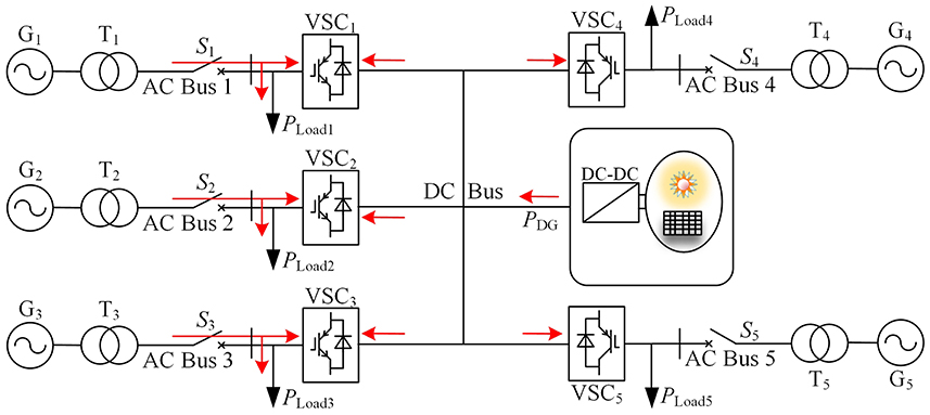
Figure 1. Five-port flexible interconnected distribution system. VSC, Voltage Source Converter.
2.2 Control modes for multi-port FMSS
The VSCs in this multi-port FMSS flexible interconnected distribution system are equipped with three key control modes to cope with a system's steady-state operation or fault-state operation conditions.
2.2.1 P-Q control mode
The P-Q control mode can set the power command value according to the feeder current distribution, load situation, and optimized operation conditions and directly control the active and reactive power output from the VSC. The power control accuracy can be improved by adopting the steady state inverse model of the system in Equation 1:
The block diagram of the control structure is shown in Figure 2, with the superscript asterisk (*) indicating the reference value of the corresponding physical quantity, and those containing superscript asterisks (*) in the lower diagram also representing the reference values of the corresponding physical quantities.
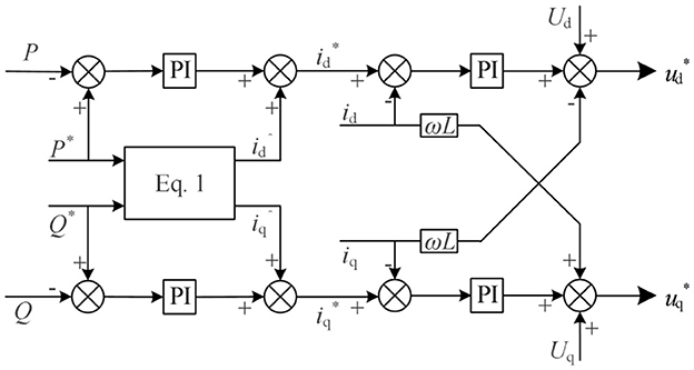
Figure 2. P-Q control mode.
2.2.2 Udc-Q control mode
The Udc-Q control mode stabilizes the DC bus voltage by setting the DC bus voltage reference value to ensure a balanced VSC active power transfer in the FMSS. The block diagram of the control structure is shown in Figure 3.
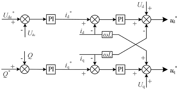
Figure 3. Udc-Q control mode. PI, Proportional Integral.
2.2.3 Droop control mode
The Droop control mode is in the interconnected distribution network system in the feeder loss of a power environment. The loads connected to the fault feeder lose grid support, and using a fixed AC voltage and a fixed frequency control to ensure that there is no loss of power to the load here. Figure 4 shows the block diagram of the Droop control structure, in which P0, Q0, f0, and U0 are the reference values of active power, reactive power, output voltage frequency, and output voltage amplitude, respectively; kP and kQ are the corresponding Droop coefficients, respectively; and f * and V * are the frequency and amplitude of the generated reference voltage. The Droop control adjusts the active and reactive output power of the VSC by adjusting the phase and amplitude of its output voltage, which enhances the fault tolerance of the interconnection system to cope with feeder fault conditions.
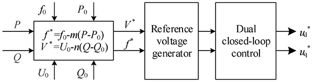
Figure 4. Droop control mode.
3 Flexible interconnected distribution network system operation optimization and load regulation strategy
3.1 Transformer loss characterization
The FMSS is directly connected to the low-voltage side of the distribution transformer, and the line loss is negligible. Most of the losses in the distribution system are transformer losses, which are ~70% (Tu et al., 2023), and the comprehensive transformer loss is closely related to the transformer loading rate, so it is necessary to consider the variability of the economic operation of the transformer with different models and capacities. Zhong Guo Zhi Jian Chu Ban She (2009) puts forward the concept of comprehensive power loss and comprehensive loss rate of transformer, and its calculation equation is
where ΔPT_loss is the transformer's integrated power loss, PT0 is the transformer no-load loss (kW), λ is the transformer load factor, PTz is the transformer-rated load power loss (kW), ΔPT_loss% is the transformer's integrated power loss rate, STN is the transformer's rated capacity (kVA), and cosϕ is the transformer power factor of 0.95.
In this article, the S9 series transformers are analyzed as an example, and the comprehensive loss-rate curves of 315, 250, and 200 kVA for the S9 series transformers can be obtained from Equations 2, 3, as shown in Figure 5. It can be seen that the transformer's light-load and heavy-load operation will lead to an increase in the comprehensive loss rate of the transformer, and the optimal economic operation interval of the S9 series transformer is [0.25–0.75].
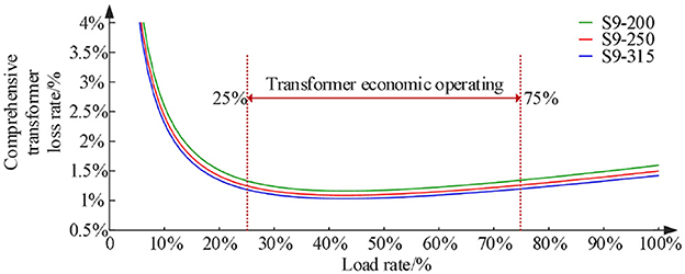
Figure 5. The S9 series transformer comprehensive loss rate curve.
3.2 Load regulation strategies for flexible interconnected distribution systems
3.2.1 Load regulation strategy objective function
According to the analysis of the loss characteristics of an S9 series transformer, the selected transformer capacity is different, and the capacity of each port VSC in the FMSS is also different; in the distribution network feeder failure, FMSSs need to carry out the corresponding mode switching, according to the actual situation of the system operation, to ensure the system's economy and stability. This article puts forward a kind of economic operation interval for the transformer in which the total loss amount for the multi-port flexible interconnection distribution system is minimized. The objective function of load regulation strategy and loss minimization load regulation strategy are described, and the objective function is defined as Equation 4:
where Eall_loss is the total loss of the interconnected distribution system and PFi_loss is the active power transmission loss of VSCi.
Based on the objective function, define the calculation of each type of loss as Equation 5:
where PTi0 is the transformer Ti no-load loss (kW), PTiZ is the transformer Ti load loss (kW), λi is the load ratio of the transformer Ti, PTi is the secondary-side output power of the transformer Ti (kW), STNi is the rated capacity of the transformer Ti (kVA), cosϕ is the power factor of the transformer Ti, PFi is the active power transmitted by the converter i (kW), and the efficiency of the converter η are 98%.
3.2.2 Constraints related to load regulation strategies
The optimal economic operating interval of the transformer is constrained to be Equation 6:
The AC-side power balance constraint of the flexible interconnected distribution system is Equation 7:
The FMSS DC-side power balance constraint is Equation 8:
where PDG represents the active power (kW) emitted by the PV.
The FMSS port capacity constraints are Equation 9:
3.3 Port selection for constant DC bus voltage control
When the VSC capacity of each port is the same, there is no need for Udc-Q control port selection. Therefore, this article focuses on the optimal selection of Udc-Q control ports in VSCs with different capacities. The traditional selection method tends to choose the VSC with the largest port capacity as the master; however, this method neglects the real-time operation status of the port and the economic operation of the distribution transformer in the interconnected system. The stability and strength of the connected distribution network also affect the control effect of the converter, which can control the DC bus voltage more effectively in the case of higher stability and strength of the distribution network. Based on this, the regulation ability of the distribution transformer can directly reflect the stability and strength of the distribution network can be considered, which is mainly reflected in the size of the transformer capacity. In summary, based on the actual operation of each port VSC and the load regulation strategy proposed in Section 2.2, the VSC with the highest comprehensive evaluation score, CEI, is selected to adopt the Udc-Q control mode, and the comprehensive evaluation score CEI is defined as Equation 10:
where Fsci is the VSCi capacity score, Tsci is the distribution transformer capacity score, Ssci is the VSCi capacity regulation margin score, α and β are the weight coefficients of the scores, where (α + β = 1), and the corresponding calculation is as follows Equation 11:
where SFNi and SFi are the rated capacity and present output apparent power, respectively, of VSCi and STi is the present output apparent power of distribution transformer i.
3.4 Operational structure of the flexible interconnected distribution system
By analyzing the loss characteristics of distribution transformers and proposing the objective function and constraints related to the load regulation strategy, as well as the selection method of the Udc-Q control port of the master station, the two-stage optimized regulation operation structure of the multi-port flexible interconnected distribution network system in steady-state operation and faults is shown in Figure 6. The smooth switching method of the FMSS modes under the improved state tracking control, mentioned in Stage II, is elaborated in detail in Chapter 4.
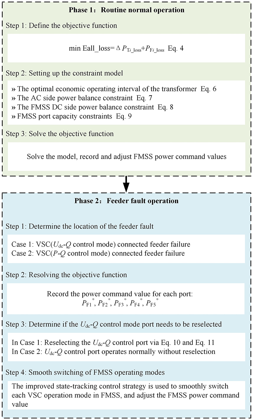
Figure 6. Diagram of the operational structure of a flexible interconnected distribution system. FMSS, flexible multi-state switch; VSC, Voltage Source Converter.
4 Modal operation regulation strategy via FMSS
4.1 Improved state tracking control design
To cope with the voltage impact and power fluctuation brought about by the instantaneous mode switching of each port of the FMSS, this article proposes an improved state-tracking control method, which can effectively reduce the high computation amount brought by the redundant PI in the traditional method and effectively reduce the system overshooting amount, and the control structure is shown in Figures 7A, B, which defines that the front-stage control adopts the Udc-Q control mode, the back-stage control is a Droop control mode, and the back-stage control is the control mode that follows the front-stage control output. The improved state tracking control is to make a difference between the output voltage of the back-stage control input and the output voltage of the front-stage control during the steady-state operation of the system, which is adjusted by the PI controller, so that the voltage output of the back-stage control before the mode switching follows the output of the front-stage control in real time. When the feeder of the multi-port flexible interconnected distribution system fails and the FMSS control mode needs to be switched, the output voltage of the two modes can be matched at the switching instant to ensure the consistency of the output state, and the smooth switching between different operation modes of the FMSS can be realized by reasonably controlling the states of the A-switch and the B-switch.
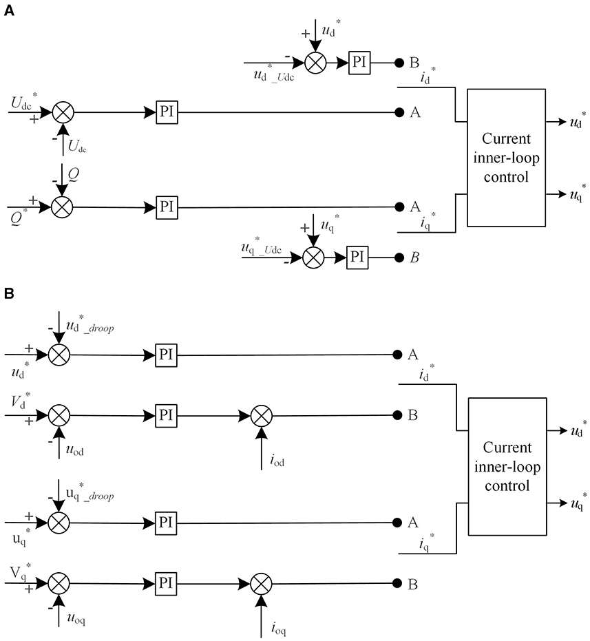
Figure 7. Schematic of the improved state-tracking control. (A) Improved state tracking in Udc-Q control. (B) Improved state tracking in Droop control.
During steady-state operation, all A switches in Figure 7 conduct, and at this time, _droop and _droop in the Droop state-tracking control track the output voltage and of each port in real time through the PI controller. When Udc-Q control port connected feeder fault is detected, _droop and _Udc as well as _droop and _Udc outputs are equal after current inner-loop control due to the introduction of the state-tracking control. when the FMSS mode is switched, all the A switches are turned off and the B switches are turned on to adjust the port output active voltages by generating the Droop-control reference voltage V * and the reference frequency f * to regulate the port output active power and reactive power. After the integrated time delay, the VSC at the fault end is smoothly switched to the Droop control mode by improving the state tracking control, and at the same time, the VSC with the highest integrated evaluation score is selected from the remaining P-Q control ports to be switched to the Udc-Q control mode, to maintain the stability of the DC bus voltage and ensure the balance of the system transmission power. The same is true of the connected feeder fault at the P-Q side, which is only required to be switched to the Droop control mode by this method, and the master port does not need to be switched to the Droop control mode. Similarly, the control port only needs to be switched to Droop control mode under this method, and the master port does not need to be reselected.
4.2 Mode smooth switching control flow
When the distribution network feeder is faulty, the FMSS mode smooth switching control flow is shown in Figure 8, if the faulty feeder is connected to the Udc-Q control port, switch S is connected to 0; if the faulty feeder is connected to the P-Q control port, switch S is connected to 1. According to the proposed load regulation strategy and the master port selection method, respectively, state-tracking control is carried out to realize the output matching of the output voltage at the instant of switching to the Droop control, thus enabling the interconnection system to smoothly transition to the emergency control mode after a feeder failure.
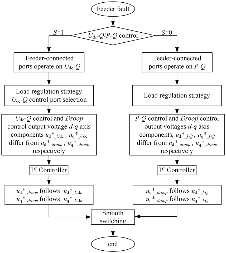
Figure 8. Flow chart of mode smooth switching control. PI, Proportional Integral.
4.3 Pre-synchronization design
During the switching process of the FMSS control mode, the phase angle of the fault feeder voltage is affected by voltage and frequency fluctuations, and a certain difference is generated between the phase angle and the grid power. When the switching is completed, the system is in an emergency control state for a time, and to avoid a large transient shock due to phase inconsistency when reconnecting to the grid, considering the new grid-connecting conditions is necessary. Therefore, this article carries out the design of pre-synchronization, mainly considering phase pre-synchronization; by implementing phase pre-synchronization control, the feeder phase can be gradually approximated with the grid phase until the phase angle difference falls within the range permitted by the grid-connecting conditions and then for the grid-connecting closing process. Pre-synchronization control is shown in Figure 9.
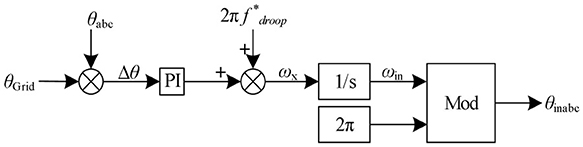
Figure 9. Schematics of pre-synchronization control.
When the pre-synchronization starts, the collected grid phase θGrid creates a difference with the feeder phase θabc to get the phase difference Δθ. The PI regulator outputs the frequency compensation quantity ωx, which is summed with the frequency signal 2πf*droop generated under the Droop control; then generates the feeder phase θinabc to be transmitted to the VSC as the continuous reference phase by the Mod module of the residual module, which ensures the coherence of the feeder phase with the grid phase and the smooth continuity of switching action before the grid-connecting and -switching action; and provides phase guarantee for grid-connecting switching in the Droop control mode.
5 Simulation verification
In this article, a five-port FMSS flexible interconnected distribution system is constructed by simulation on the MATLAB/Simulink platform, and the corresponding system operating parameters are set, as shown in Table 1.
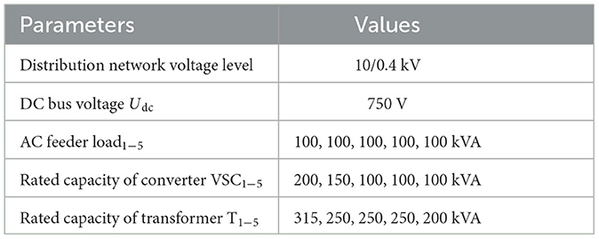
Table 1. Simulation parameters of a flexible interconnected system.
In normal steady-state operation mode, defining the power inflow VSC as positive in direction, the PV power generation system steadily outputs active power PDG = 20 kW through the Maximum Power Point Tracking (MPPT) control. From 0 to ~0.48 s, the system operates normally when considering the proposed load regulation strategy to optimize the transmission power command values of each port, PF1, PF2, PF3, PF4, and PF5, as 0, −3.761, −3.019, −3.019, and −10.20 kW, respectively, the combined loss is only 5.736 kW.
The failure of the distribution network i feeder at 0.48 s will result in the loss of support from the larger grid for the connected loadi on the low-voltage side of the transformer Ti, and emergency load transfer is required. At this time, the equivalent circuit of the interconnection system can be uniformly analyzed in Figure 10. After the action of the isolation switch Ki, the intelligent power distribution device FMSS sends out a mode-switching command, and after the 0.02 s integrated time delay, the corresponding mode smooth switching is carried out at the moment of 0.5 s.
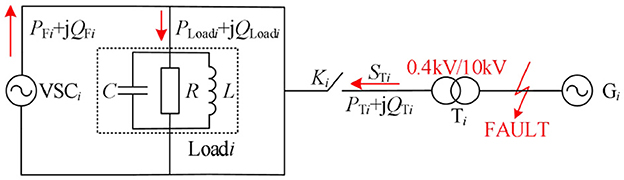
Figure 10. Equivalent circuit diagram of a flexible interconnected system. VSC, Voltage Source Converter.
Taking the distribution network 1 feeder fault state as an example, at this time, distribution network 1 transmits power ST1 = PT1 + jQT1 = 0 via T1, and the active power required by load 1 needs to be provided by other VSC2, VSC3, VSC4, VSC5, and DG, and transmitted to load1 emergency power supply via VSC1. Therefore, it is necessary to carry out the corresponding mode-switching action and power regulation commands for each VSC in the FMSS, and at this time, the transmitted power relationship is Equation 12:
The voltage and current of bus 1 under the hard switching of VSC1 port from Udc-Q control mode to Droop control mode are shown in Figures 11A, B, and it can be found that the peak value of voltage impact of AC bus 1 under the unadopted regulation strategy reaches 404 V (the system steady-state operation amplitude um is ~311 V), and the voltage overrun part exceeds the rated amplitude um by 29.9%; the peak value of current impact reaches 279 A (the current amplitude im1 is 215 A under the emergency control mode), and the current overrun part exceeds the emergency current amplitude im3 by 29.76%. Similarly, through real-time monitoring of bus 3 voltage and current, and the hard switching of P-Q control to Droop control in the fault condition of distribution network feeder 3, the peak value of AC bus 3 voltage impact reaches 375 V, with the voltage exceeding the rated amplitude um by 20.6%, and the peak value of current impact reaches 260 A (current amplitude im3 under emergency control mode is 214 A), with the current exceeding the emergency current amplitude im3 by 21.50%.
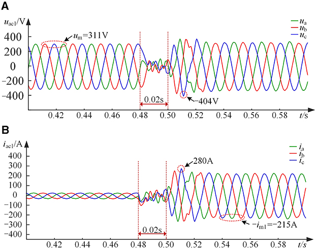
Figure 11. Voltage and current of bus 1 during hard switching. (A) Voltage of bus 1 during hard switching. (B) Current of bus 1 during hard switching.
Therefore, Scenarios 1, 2, and 3 are designed according to the system failure types and recovery scenarios and are verified in simulation as follows.
5.1 Scenario 1—Failure of feeder connected to Udc-Q control port
When a fault occurs on the distribution network feeder 1, the need to switch VSC1 to the Droop control mode is urgent. To maintain the system transmission power balance, according to the selection method of fixed DC bus voltage control ports proposed in Section 2.3, the port capacity regulation margin score is taken as the main factor, its weighting coefficient α is assigned to be 0.6, the distribution transformer capacity score is taken as the secondary factor of port selection, its weighting coefficient β is assigned to be 0.4, the VSC2 with a higher CEI score is selected from the remaining P-Q control ports switches to the Udc-Q control mode, and the specific CEI scores are shown in Table 2; VSC3, VSC4, and VSC5 continue to maintain the P-Q control mode, and the power is adjusted in real time by the re-optimized power adjustment commands. Meanwhile, the transmission power commands PF1, PF2, PF3, PF4, and PF5 of each port are corrected to −100, 28.71, 25.45, 25.84, and 0 kW, respectively, and the integrated loss is 9.083 kW.
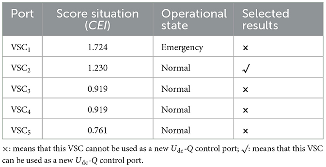
Table 2. Comprehensive evaluation scores for each Voltage Source Converter port.
As shown in Figures 12–14, when the control strategy proposed in this article is adopted, the AC voltage impact of bus 1 at the instant of mode switching decreases to 326 V, and the voltage overrun is only 4.82%um. The current impact decreases to 225 A, the current overrun is only 4.65%im1, and the impact suppression effect is obvious; the DC voltage fluctuates little after mode switching, and the maximal voltage deviation is smaller than that of the traditional smooth switching. After mode switching, the DC-side voltage fluctuation is small, and the maximum voltage deviation rate is smaller than that of the traditional smooth switching method, which is only 0.134%. The active power response of each port is fast, and the active power overshooting offset rate is smaller than that of the traditional smooth switching method, which is only 18.42%.
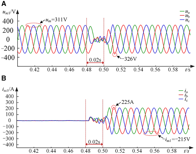
Figure 12. Voltage and current of bus 1 during improved state tracking control in Scenario 1. (A) Voltage of bus 1 during improved state tracking control. (B) Current of bus 1 during improved state tracking control.
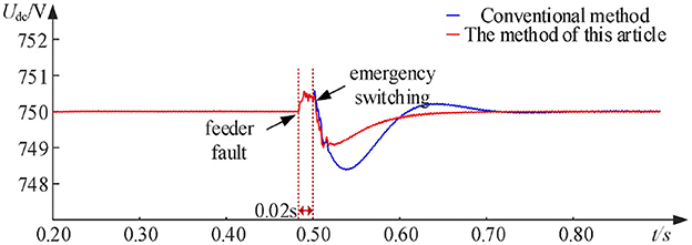
Figure 13. DC bus voltage in Scenario 1.
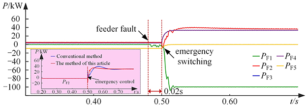
Figure 14. Active power transmitted by the five ports in Scenario 1.
5.2 Scenario 2—Failure of feeder connected to P-Q control port
When the distribution network 3 feeder fails, at this time, VSC3 needs to be urgently switched to Droop control mode, and load3 is supported by the other two ends VSC1, VSC2, VSC4, VSC5, and DG. As shown in Figures 15–17, after a fault occurs at 0.48 s, the DC-side voltage will produce a small fluctuation, and after a 0.02 s integrated time delay, VSC3 is switched to the Droop control mode at 0.5s, and the power commands PF1, PF2, PF3, PF4, and PF5 are corrected to be transmitted by the VSC1, VSC2, VSC3, VSC4, and VSC5, respectively, of each port by means of the proposed load regulation strategy; the values are 39.12, 22.62, −100, 18.26, and 0 kW, respectively, and the integrated loss is 8.948 kW. After adopting the FMSS smooth switching control strategy proposed in this article, the AC voltage impact of bus 3 at the instant of mode switching drops to 329 V, and the voltage overrun is only 5.78%um. The current impact drops to 227 A, and the current overrun is only 6.07%im3, with a significant impact suppression effect. The voltage fluctuation of the DC side is small after the mode switching, and the maximal voltage deviation rate is smaller compared to that of the traditional smooth switching method, which is only 0.180%. The output active power of each port responds quickly, and the active power overshoot offset rate is smaller than that of the traditional smooth switching method, only 15.03%.
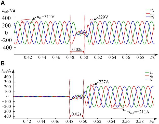
Figure 15. Voltage and current of bus 3 during improved state tracking control in Scenario 2. (A) Voltage of bus 3 during improved state tracking control. (B) Current of bus 3 during improved state tracking control.
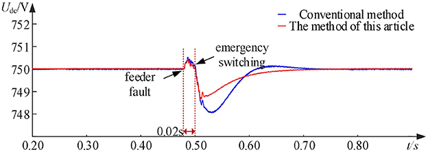
Figure 16. DC bus voltage in Scenario 2.

Figure 17. Active power transmitted by the five ports in Scenario 2.
5.3 Scenario 3—Grid-connected pre-synchronization control
When the five-port VSC under scenarios 1 and 2 is in emergency control mode, each port is in Udc-Q control mode, P-Q control mode, and Droop control mode, respectively. When the abnormal state is lifted and new grid-connection conditions need to be considered, grid-connection pre-synchronization processing is required, and VSC1, which is in the Droop control mode under Scenario 1, is able to quickly complete phase synchronization. At the instant of grid-connection closing action, VSC1 switches back to Udc-Q control mode to re-ensure DC bus voltage stability and power transfer balance, and VSC2 also switches back to P-Q control mode from Udc-Q control mode to reregulate system power. Thus, the interconnected system is restored to steady-state operation. Similarly, in Scenario 2, after VSC3 in Droop control mode starts pre-synchronization, it can synchronize its AC voltage phase to the grid voltage phase within 0.05 s, and then switch VSC3 control mode to P-Q control mode while waiting for the grid-closing action. Thus, the interconnection system restores the steady-state operation. Scenario 2 phase pre-synchronization waveforms and VSC transmission power waveforms of each port are shown in Figures 18, 19.
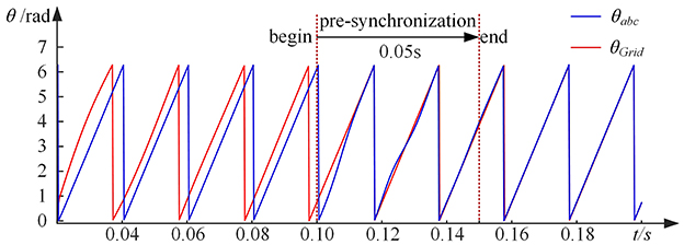
Figure 18. Waveform of phase pre-synchronization control.
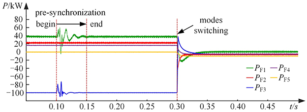
Figure 19. Active power transmitted by the five ports in Scenario 3.
6 Conclusion
The multi-port flexible interconnected distribution system multimode smooth switching control strategy proposed in this article, including the load regulation strategy, the Udc-Q control port selection method, the improved state tracking control strategy, and the grid-connected pre-synchronization method, can solve the problem of reselection of the Udc-Q control port of the main station due to the fault of the distribution feeder under the guarantee of the economic operation of the interconnected system, and the need of the FMSS control method to the feeder voltage, current impact, and power fluctuation problems brought about when switching is carried out. The conclusions are as follows:
(1) The method of selecting the Udc-Q control port of the master station proposed in this article can cope with the situation in which the connected feeder of the master station fails and the master port faces reselection. The method is to select the VSC with the largest comprehensive evaluation score CEI from other P-Q control ports as the new master station, which continues to maintain the DC bus voltage stability and ensures the interconnected system power transfer balance. The maximum voltage deviation rate is within 0.2% after switching.
(2) The improved state-tracking control strategy proposed in this article can make the output voltages of the FMSS front and rear control modes switching instantly match quickly, whether it is a P-Q control or Udc-Q control port feeder failure, the voltage and current shocks brought about during the mode-switching process can be suppressed within 6% of its rated amplitude, and the transient regulation process can be greatly shortened.
(3) The control strategy proposed in this article can realize smooth switching between different modes of a multi-port flexible interconnected distribution system and give full play to the FMSS's ability to regulate the distribution network current. It is beneficial to the flexible interconnection system after large-scale DG access to provide emergency power transfer support for power loss loads in response to feeder failure environment, which is of great significance to enhance the sustainable and stable power supply and economic operation capability of the new type of distribution network based on flexible interconnection technology.
Data availability statement
The original contributions presented in the study are included in the article/supplementary material, further inquiries can be directed to the corresponding author.
Author contributions
DP: Writing – original draft, Writing – review & editing. YY: Writing – original draft, Writing – review & editing. ZhiW: Writing – review & editing. JG: Writing – original draft, Writing – review & editing. WW: Writing – review & editing. ZheW: Writing – review & editing. HY: Writing – review & editing. YZ: Writing – review & editing.
Funding
The author(s) declare financial support was received for the research, authorship, and/or publication of this article.
Conflict of interest
The authors would like to thank the project supported by Science and Technology Project of State Grid Jilin Electric Power Company (SGJLCC00KJJS2203595). The funder had the following involvement in the study: writing – review & editing.
DP, ZhiW, HY, and YZ were employed by State Grid Changchun Power Supply Company.
The remaining authors declare that the research was conducted in the absence of any commercial or financial relationships that could be construed as a potential conflict of interest.
Publisher's note
All claims expressed in this article are solely those of the authors and do not necessarily represent those of their affiliated organizations, or those of the publisher, the editors and the reviewers. Any product that may be evaluated in this article, or claim that may be made by its manufacturer, is not guaranteed or endorsed by the publisher.
References
Dong, X., Liu, Z., Li, P., Song, G., Wu, Z., and Chen, L. (2018). Intelligent distribution network control technology based on multi-terminal flexible distribution switch. Proc. CSEE 38, 86–92. doi: 10.13334/j.0258-8013.pcsee.172359
Duan, Q., Sha, G., Sheng, W., Yang, W., Wang, Z., and Fu, L. (2020). Multi-mode operation of flexible interconnection system of distribution network and its control strategy. Power Automat. Eq. 40, 9–24. doi: 10.16081/j.epae.202007025
Feng, T., and Liu, F. (2016). Control strategy for operation transfer of micro-grid based on hybrid energy storage system. J. Northeast Dianli Univ. 36, 11–15. doi: 10.19718/j.issn.1005-2992.2016.03.003
Hu, P., Zhu, N., Jiang, D., Ju, P., Liang, Y., and Wu, B. (2021). Research progress and prospects of key technologies of flexible interconnected smart distribution network. Automat. Electr. Power Syst. 45, 2–12.
Ji, H., Wang, C., Li, P., Ding, F., and Wu, J. (2019). Robust operation of soft open points in active distribution networks with high penetration of photovoltaic integration. IEEE Trans. Sustain. Energy 10, 280–289. doi: 10.1109/TSTE.2018.2833545
Li, P., Wang, R., Ji, H., Song, Y., Yuan, Z., and Yu, H. (2021). Research and prospect of planning for low-carbon smart distribution network. Automat. Electr. Power Syst. 45, 10–21.
Lin, J., Kong, X., Zheng, J., Zhou, F., Wang, C., and Zhang, L. (2021). “A smooth operating-state-switching method used in multi-terminal flexible interconnected device,” in 2021 IEEE Sustainable Power and Energy Conference (iSPEC) (Nanjing: IEEE), 371–376.
Liu, J., and Wang, S. (2023). Study on smooth switching control strategy for grid connection and off-grid. Electr. Eng. 29–31, 35. doi: 10.19768/j.cnki.dgjs.2023.02.009
Liu, Y., Sun, M., Hu, C., Li, Z., and Ban, M. (2024). Smooth switching strategy for flexible multi-state switches based on linear active disturbance rejection control. Power Syst. Technol. 48, 1663–1672. doi: 10.13335/j.1000-3673.pst.2023.0117
Sarantakos, I., Zografou-Barredo, N. M., Huo, D., and Greenwood, D. (2021). A reliability-based method to quantify the capacity value of soft open points in distribution networks. IEEE Trans. Power Syst. 36, 5032–5043. doi: 10.1109/TPWRS.2021.3071088
Tian, L., Tang, Z., Tian, C., and Zhu, R. (2017). Research on smooth switching of microgrid based on state follower. Power Syst. Technol. 41, 1285–1290. doi: 10.13335/j.1000-3673.pst.2016.1543
Tu, C., Wang, X., Yang, W., Guo, Q., Lu, B., and Xiao, F. (2023). Soft open point control strategy considering economic operation area of distribution transformer. Power Syst. Technol. 47, 848–858. doi: 10.13335/j.1000-3673.pst.2021.2126
Wang, C., Ji, J., Ji, H., Yu, H., Wu, J., and Li, P. (2022). Technologies and application of soft open points in distribution networks. Autom. Electr. Power Syst. 46, 1–14. doi: 10.7500/AEPS20210514005
Wang, J., Huang, W., Yu, M., Tai, N., and Ma, Z. (2022). Smooth control strategy for emergency switching of interconnected microgrids via FMS. Proc. CSEE 42, 7695–7705. doi: 10.13334/j.0258-8013.pcsee.211684
Wang, X., Guo, Q., Tu, C., Che, L., Yang, W., Xiao, F., et al. (2022). A two-layer control strategy for soft open points considering the economical operation area of transformers in active distribution networks. IEEE Trans. Sustain. Energy 13, 2184–2195. doi: 10.1109/TSTE.2022.3189089
Wang, X., Qi, G., Tu, C., Li, J., Xiao, F., and Wan, D. (2023). A two-stage optimal strategy for flexible interconnection distribution network considering the loss characteristic of key equipment. Int. J. Electr. Power Energy Syst. 152:109232. doi: 10.1016/j.ijepes.2023.109232
Wang, Z., Liu, G., Pang, D., Wang, Y., Yu, B., and Wang, Z. (2024). Optimal operation of flexible interconnected distribution grids based on improved virtual synchronous control techniques. Front. Energy Res. 12:1356227. doi: 10.3389/fenrg.2024.1356227
Wei, C., Li, J., Tu, C., Wang, X., Guo, Q., and Xiao, F. (2023). Optimal regulation and control strategy for flexible interconnected distribution network considering loss characteristics of transformers and soft open points. Automat. Electr. Power Syst. 47, 69–78.
Xiao, J., Gang, F., Jiang, X., Huang, R., Wei, T., and Zhang, W. (2017). Flexible distribution network: definition, morphology and operation mode. Power Syst. Technol. 41, 1435–1446. doi: 10.13335/j.1000-3673.pst.2017.0462
Yang, W., Tu, C., Lan, Z., Xiao, F., Guo, Q., and Wang, X. (2021). Flexible interconnection strategy between DC microgrid and AC distribution grid based on energy storage flexible multi-state switch. Electr. Power Automat. Eq. 41, 254–260. doi: 10.16081/j.epae.202104021
Zhang, G., Shen, C., Peng, B., Zhu, Y., Wang, C., and Zheng, M. (2019). Smooth switching strategy of flexible multi-state switch in the case of feeder fault. High Volt. Eng. 45, 3050–3058. doi: 10.13336/j.1003-6520.hve.20190924003
Keywords: flexible multi-state switch, feeder fault, improved state tracking control, load regulation strategy, smooth switching approach
Citation: Pang D, Yin Y, Wang Z, Ge J, Wang W, Wang Z, Yi H and Zhuang Y (2024) Smooth control strategy for emergency switching of multi-port flexible interconnected distribution system modes. Front. Smart Grids 3:1449152. doi: 10.3389/frsgr.2024.1449152
Received: 14 June 2024; Accepted: 22 July 2024;
Published: 20 August 2024.
Edited by:
Linbin Huang, ETH Zürich, SwitzerlandReviewed by:
Kehao Zhuang, Zhejiang University, ChinaXin Wang, City University of Hong Kong, Hong Kong SAR, China
Copyright © 2024 Pang, Yin, Wang, Ge, Wang, Wang, Yi and Zhuang. This is an open-access article distributed under the terms of the Creative Commons Attribution License (CC BY). The use, distribution or reproduction in other forums is permitted, provided the original author(s) and the copyright owner(s) are credited and that the original publication in this journal is cited, in accordance with accepted academic practice. No use, distribution or reproduction is permitted which does not comply with these terms.
*Correspondence: Yu Yin, c3N3MXBvbmV5eUAxNjMuY29t