 Ze-Sen Li
 Yue-Li Li
- College of Electronic Science and Technology, National University of Defense Technology, Changsha, China
Forward-looking imaging for maneuvering platforms has garnered significant interest in many military and civilian fields. As the maneuvering trajectory in the scanning period can be simplified as the constant acceleration maneuver, monopulse imaging is applied to enhance the azimuthal resolution of the forward-looking image. However, the maneuver causes severe range migration and Doppler shift; this often results in range location error due to the space-varying Doppler shifts and the failure of angle estimation. We propose a decimation keystone algorithm based on the chirp-Z transform (CZT). First, the pulse repetition frequency (PRF) is decimated with an integer; thus, the azimuthal sampling sequence is decimated into many sub-sequences. Then, the linear range walk correction (LRWC) is performed on each sub-sequence using the keystone transform, significantly reducing the influence of the change of Doppler-ambiguity-number on range location. Further, the sub-sequences are regrouped as one sequence, and the range curvature due to the acceleration is compensated in the frequency domain. Finally, the varying Doppler centroid in each coherent processing interval (CPI) is analyzed and compensated for the sum-difference angular measurements. Simulation results demonstrate the effectiveness of the proposed algorithm for forward-looking imaging under constant acceleration maneuvers and the feasibility of range location error correction.
1 Introduction
High-resolution microwave imaging of the front area of an aircraft has raised significant interest among researchers in recent years. Doppler beam sharpening (DBS) and monopulse imaging are two widely-used techniques for enhancing cross-range/angular resolution in airborne scanning radar sensors. Doppler beam sharpening cannot resolve multiple scatterers in the large squint cases because of the severe decline of the Doppler centroid differences, resulting in a “blind area” in the forward-looking direction. Forward-looking monopulse imaging refers to the two-dimensional microwave imaging of the front view of an aircraft based on monopulse techniques. Generally, the radar antenna scans across the front scene, and the monopulse technique is utilized to enhance the azimuthal resolution of the image (Griffiths, 1998; Nickel, 2006; Zhang et al., 2016). The method is characterized by low system complexity, good adaptability for the flight path, and significant resolution enhancement. However, Monopulse technique fails to resolve target multiplicity in the range and azimuth resolution bin of an ordinary monopulse radar. The angle glint caused by target multiplicity may result in imaging blurring in forward-looking images, especially for extended targets comprised of a significant number of scatterers. Combining the amplitude-comparison monopulse technique with the Doppler beam sharpening (DBS) technique, the Doppler difference of the scatterers in the main lobe is used to separate them into different Doppler units (Lu et al., 2011). Then, the sum-difference Doppler estimates are reconstructed and used to estimate the scatterers’ angles. The method can significantly alleviate the image blurring caused by the freedom limit in the angular dimension (Li et al., 2021).
Usually, the uniform motion in the coherent processing interval (CPI) often leads to severe space-varying range migration (Li et al., 2012) and thus affects the focusing performance and positioning accuracy. Therefore, linear range walk correction (LRWC) is implemented based on the keystone transform for forward-looking imaging (Li et al., 2012). However, the change in the Doppler-ambiguity-number due to the varying Doppler shifts of targets in different directions should also be addressed.
The maneuvering trajectory may be simplified as the constant acceleration motion during the CPI for monopulse estimation. And the change of platform velocity in the scanning process causes non-linear range migration and space-varying Doppler shift. So, the range curvature and the Doppler shifts need to be addressed. Especially when the scanning mode is adopted, the change of Doppler-ambiguity-number for scatterers situated at the larger squint angles may cause severe range location error (Li et al., 2022). Moreover, the angle measurement based on the Doppler estimates may suffer from varying Doppler shifts due to accelerations.
Forward-looking radar imaging aims to accumulate the scatterers’ reflective energy coherently. This is like detecting a moving target using a stationary radar system. Both applications must overcome the related motion between the radar’s antenna phase center (APC) and the target. The range migration and the Doppler history of the echoes are similar. Therefore, the methods proposed for detecting targets with uniform acceleration motion may be feasible to compensate for motion error in forward-looking imaging.
To accumulate a target’s energy in the case of constant acceleration motion, the range walk is generally corrected with the keystone transform, and the second-order phase error caused by accelerations is compensated using a dechirping processing (Wu et al., 2009). Li X. et al. (Li et al., 2015) proposed a coherent accumulations algorithm based on the keystone transform and fractional Fourier transform (FrFT). After LRWC, the signals are extracted for FrFT to complete energy accumulation. However, since only the range walk is compensated, the range curvature results in poor accumulation performance when the acceleration cannot be ignored. Sharif R. et al. proposed a method based on the keystone transform and Wigner-Hough (Sharif and Abeysekera, 2007). The second-order keystone transform removes the range curvature (Kirkland, 2011) (Yang et al., 2011). First, the quadratic coupled term of range frequency and the slow time is decoupled through the second-order keystone transform. Second, a matched filter is reconstructed to compensate for the Doppler centroid offset and estimate the accelerations. Finally, the second stage of the second-order keystone transform is used to correct range curvature and accumulate the target energy. However, in all the above research, the change of the Doppler ambiguity number is not considered because only moving targets in the main lobe are concerned in the detection cases. Furthermore, the second-order keystone transforms mean an extensive computation load.
In imaging cases, the motion parameters are usually measured using the GPS/INS mounted on the platform. On the contrary, the range migration and the Doppler shift due to targets or scatterers from the scene differ from the directions. So, space-varying motion compensation plays a vital role in the forward-looking imaging. To resolve the problem, a decimation keystone algorithm is proposed in the paper. First, the range walk is corrected using the decimation keystone transform, which solves the change of the Doppler ambiguity number by reducing the spatial sampling rate. Then, a compensative factor in the frequency domain is constructed to eliminate the range curvature. Finally, the effect of accelerations on the Doppler centroid is considered and removed during angle measurement. Simulation experiments verify the effectiveness of the proposed method.
2 Analysis of the signal model for forward-looking imaging on uniformly accelerated platforms
2.1 A geometric model for forward-looking imaging on uniformly accelerated platforms
Forward-looking monopulse imaging based on the scanning mode improves the azimuthal resolution of the real-aperture image of the front scene through the monopulse technique (Wu et al., 2010).
Suppose the radar platform flies from
where
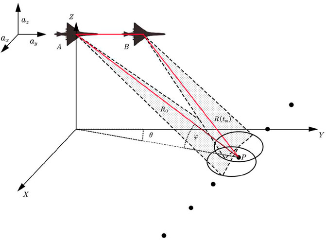
FIGURE 1. A geometric model for forward-looking imaging of a uniformly accelerated platform.
According to the image geometry, the slant range changes not only over the slow time, but also with the squint angle
2.2 Range migration and Doppler shift
Assume that the monopulse radar transmits a linear-frequency-modulation (LFM) pulse signal; the time-domain expression of the transmitted signal can be expressed by
where
The sum-difference channels time-domain echoes of the point target after range pulse compression can be expressed as
where
where
The cross-coupling phase terms are expressed as a range frequency and slow time function. The second exponential term indicates the Doppler shift, and the third shows the linear range walk due to the forward velocity. The fourth term means the extra Doppler shift, and the fifth indicates the range curvature due to the forward acceleration.
3 Range migration correction base on decimation keystone algorithm
According to 7), linear range migration and linear Doppler shift caused by the forward velocity are space-variant for targets in different directions. Traditional methods compensate for the space-variant range walk using the keystone transform (Li et al., 2012).
3.1 Traditional keystone transform and range curve compensation
The keystone transform is performed to correct the range walk in (7) in forward-looking imaging. To decouple the relationship between
which is the keystone transform (Perry et al., 1999). By substituting 8) into 7), the spectrum signal is recast as
where the traditional keystone transform eliminates the coupling between
For the high-band radar satisfies
To compensate the range curvature in the fourth exponential term, a frequency-domain factor is proposed to decouple
Considering that the slant angle in the front area is usually less than
Therefore, the range curve compensation can be manipulated in the frequency domain. By multiplying by (10), we can obtain
Performing the inverse Fourier transform to (13), yields
The slant range in the envelope indicates that the space-variant range migration has been corrected using the keystone transform and range curve compensation. However, the exponential term means the acceleration introduces an extra Doppler shift.
3.2 The decimation keystone algorithm for Doppler ambiguity compensation
For the high-band radars, as the PRF of the system is much smaller than the Doppler centroid, the Doppler ambiguity occurs. The correction of the Doppler ambiguity must combine with the keystone transform. The dependence on the Doppler ambiguity number is a limitation of the keystone transform (Zhang and Zeng, 2005) (Li, 2006) and
where
Generally,
where
where
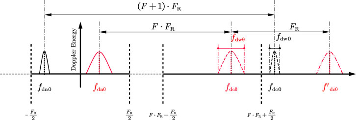
FIGURE 2. Schematic diagram of the residual velocity generated by solving Doppler ambiguity.
Since
where
A decimation keystone algorithm is proposed to solve the range location error caused by the Doppler ambiguity compensation. Suppose that the length of the sampling sequence in the slow time dimension is
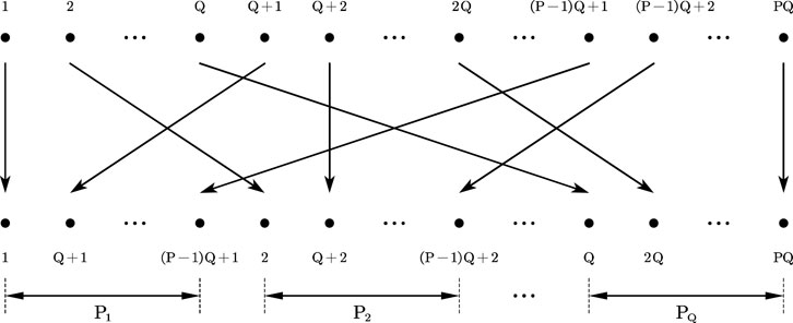
FIGURE 3. Schematic diagram of sequence decimating and rearranging.
For each sub-sequence
The residual velocity is reduced by
Since the actual signal processing is digitalized, the range frequency and the slow time in the data need to be represented as discrete variables. Three methods to implement the keystone transform have been proposed (Wang and Zhao, 2011): SINC interpolation, DFT-IFFT, and CZT. Because the computational complexity of the CZT is much smaller than the other two methods, it is used to implement the keystone transform. The process can be expressed as follows:
where
where
The flowchart of the decimation keystone algorithm is shown as Figure 4.
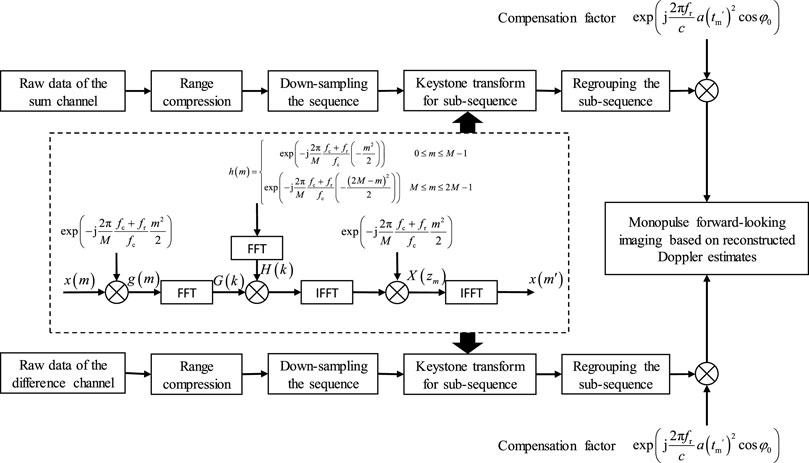
FIGURE 4. Flowchart of decimation keystone algorithm.
After range compression and motion compensation, we utilize the Doppler estimates of the sum-difference measurements to achieve monopulse forward-looking imaging (Li et al., 2021). First, target multiplicity is resolved by exploiting the different Doppler shifts caused by the relative motion between the platform and the targets in different directions. High azimuthal angle measurement accuracy of the Doppler estimates is obtained using the sum-difference amplitude-comparison technique. Subsequently, the intensity of the sum channel estimates is projected onto the image plane according to the range and angle measurements.
3.3 The effect of acceleration on the Doppler centroid and its compensation
In the geometric model for forward-looking imaging illustrated in Figure 1, when the acceleration
where
and
where the wavelength is, thus, the Doppler bandwidth is also modified as follows:
If the monopulse imaging is performed based on the Doppler estimates of the sum-difference channels, the Doppler parameters must be calculated according to (25) and (26). Otherwise, the scatterers’ energy in the main lobe is missed, and the angle cannot be measured accurately, leading to image blurring.
4 Simulation results
4.1 Point target imaging simulation
The monopulse forward-looking imaging algorithm is used for simulation to verify the proposed method (Li et al., 2021). The simulation parameters are given in Table 1. Suppose that the radar sensor is mounted on an aircraft. The velocity
TABLE 1. Simulation parameters for forward-looking scanning radar.
Figure 5 compares the forward-looking imaging results processed using the traditional method and the decimation keystone algorithm. The radar platform obeys a uniform motion. The Doppler ambiguity number of the target at
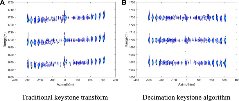
FIGURE 5. Comparison of image results of the uniform motion platform. (A) Traditional keystone transform. (B) Decimation keystone algorithm.
Figure 6 verifies the effectiveness of the range curve compensation on the constant acceleration maneuvers. Figures 6A, B present the imaging results processed by the traditional keystone transform with different accelerations. Because of the change in the Doppler ambiguity number and the range curvature, range positioning error is apparent in the images. Figures 6C, E compare the imaging results processed by the decimation keystone algorithm with the acceleration equals
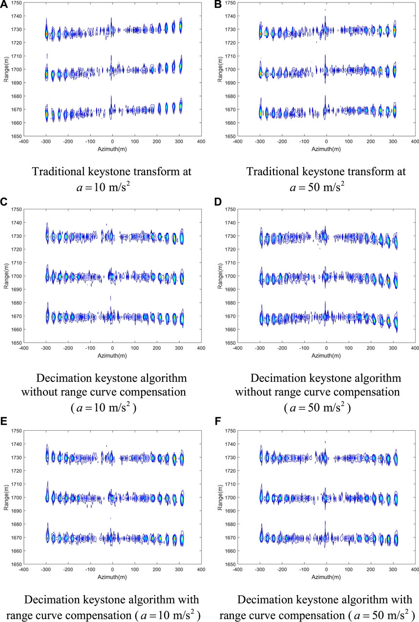
FIGURE 6. Comparison of image results of the uniform acceleration platform. (A) Traditional keystone transform at
We compare the range profiles of the point target at the azimuth distance of -300 m and the ground range of 1700 m from Figures 6B, D, F, respectively. The normalized range profiles are interpolated by five times. In Figure 7A, the curve in red represents the profile processed using the traditional keystone transform, where the displacement from the actual range is about 3 m. The curve in the blue line represents the profile processed using the decimation keystone transform, where the displacement is invisible. In Figure 7B, the red curve represents the point target’s range profile in Figure 6D. The curve in blue represents the range profile of the point target in Figure 6F. Without compensating for the range curvature, the point targets will be offset by 3 m, resulting in a misalignment of the range positioning. The integrated side lobe ratio (ISLR) is calculated by:
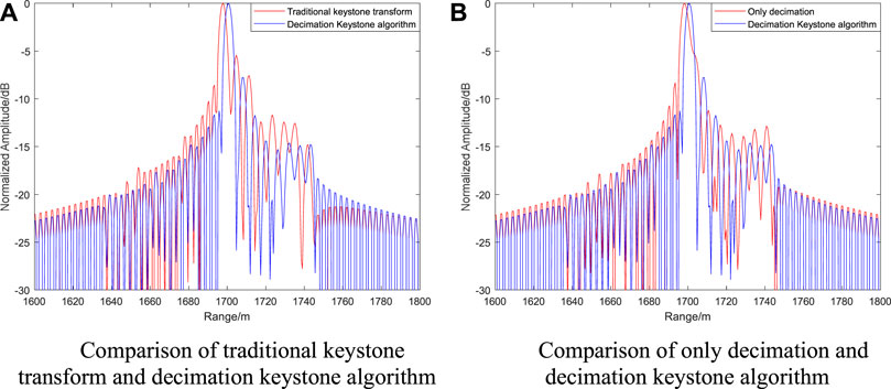
FIGURE 7. Range profiles of targets at the axis (range 1700 m, azimuth −300 m). (A) Comparison of traditional keystone transform and decimation keystone algorithm. (B) Comparison of only decimation and decimation keystone algorithm.
In Figure 7A, the ISLR of the traditional keystone transform is -9.93dB, while the ISLR of the decimation keystone algorithm is −14.65 dB. In Figure 7B, the ISLR of only decimation is −14.34 dB. The energy of the decimation keystone algorithm is more concentrated and has a better focusing effect.
4.2 Scene simulation verification
Point targets simulation verifies the effectiveness of the decimation keystone algorithm. This section demonstrates the proposed method’s feasibility in reconstructing an extended target. In the simulation, a Ku-band SAR image is used as the original scene, and the image was down-sampled by 10 with 3 m × 3 m pixel resolution, as shown in Figure 8A. The red dotted line represents the actual range location of the road’s edges in the image. The image center is at the ground position (01,700) m. The echo data are generated according to the simulation parameters in Table 1 with the acceleration equals
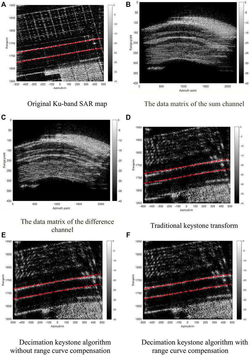
FIGURE 8. Comparison of correction results in simulation scenes. (A) Original Ku-band SAR map. (B) The data matrix of the sum channel. (C) The data matrix of the difference channel. (D) Traditional keystone transform. (E) Decimation keystone algorithm without range curve compensation. (F) Decimation keystone algorithm with range curve compensation.
Figure 8D presents the image result processed with the traditional keystone transform. The road edges are distorted and defocused because of the space-varying Doppler shift and the forward acceleration. The range offset of the targets is severe at the large azimuthal angles. Figure 8E is the imaging result processed with the decimation keystone algorithm without range curve compensation. The distortion of the road edges remains significant owing to the range curvature. Figure 8F demonstrates that the decimation keystone algorithm combined with range curve compensation can reconstruct the scene accurately. The experimental results verify the effectiveness of our proposed method.
5 Conclusion
When the airborne platform adopts the scanning mode in forward-looking imaging, the platform motion leads to range walk and Doppler shift in the target accumulation time. When the keystone transform is used for range walk correction, the point targets on both sides may suffer from the change of Doppler ambiguity number. This paper proposes the decimation keystone algorithm, which can reduce the PRF by decimating, thus reducing the residual velocity and achieving an accurate range position. Furthermore, we analyze the influence of range curvature caused by the acceleration and the Doppler shift on the imaging results for platforms with constant acceleration motion. The decimation keystone algorithm introduces a frequency-domain factor to compensate for the range curvature. Simulation results verify the effectiveness of the proposed method.
Data availability statement
The raw data supporting the conclusion of this article will be made available by the authors, without undue reservation.
Author contributions
Z-SL finished the article under the guidance of Y-LL.
Conflict of interest
The authors declare that the research was conducted in the absence of any commercial or financial relationships that could be construed as a potential conflict of interest.
Publisher’s note
All claims expressed in this article are solely those of the authors and do not necessarily represent those of their affiliated organizations, or those of the publisher, the editors and the reviewers. Any product that may be evaluated in this article, or claim that may be made by its manufacturer, is not guaranteed or endorsed by the publisher.
References
Kirkland, D. (2011). Imaging moving targets using the second-order keystone transform. IET Radar Sonar Navig. 5 (8), 902–910. doi:10.1049/iet-rsn.2010.0304
Li, W., Yang, J., and Huang, Y. (2012). Keystone transform-based space-variant range migration correction for airborne forward-looking scanning radar. Electron. Lett. 48 (2), 121–122. doi:10.1049/el.2011.2774
Li, X. L., Cui, G. L., Yi, W., and Kong, L. J. An efficient coherent integration method for maneuvering target detection[A]. Proceedings of the IET International Radar Conference 2015, October 2015, Hangzhou, doi:10.1049/cp.2015.1214
Li, Y. L., Ma, M. E., Zhao, C. H., and Zhou, Z. M. Forward-looking imaging via Doppler estimates of sum-difference measurements in scanning monopulse radar[J]. J. Radars, 2021, Vol.10(1): 131–142.
Li, Y. Range migration compensation and Doppler ambiguity resolution by keystone transform[A]. Proceedings of the 2006 CIE International Conference on Radar[C], October 2006, Shanghai, China.
Li, Z. S., Li, Y. L., and Zhang, J. F. Frequency domain compensation of the residual range walk after Keystone transform in forward-looking imaging[J]. Chin. J. radio Sci., 2022, 37(4): 568–577.
Lu, Z., Ding, Z., Liu, L., and Long, T. (2011). Adbs Doppler centroid estimation algorithm based on entropy minimization. IEEE Trans. Geosci. Remote Sens. 49 (10), 3703–3712. doi:10.1109/tgrs.2011.2142316
Nickel, U. (2006). Overview of generalized monopulse estimation. IEEE Aerosp. Electron. Syst. Mag. 21 (6), 27–56. doi:10.1109/maes.2006.1662039
Perry, R. P., Dipietro, R. C., and Fante, R. L. (1999). SAR imaging of moving targets. IEEE Trans. Aerosp. Electron. Syst. 35 (1), 188–200. doi:10.1109/7.745691
Sharif, R., and Abeysekera, S. (2007). Efficient wideband signal parameter estimation using a radon-ambiguity transform slice. IEEE Trans. Aerosp. Electron. Syst. 43 (2), 673–688. doi:10.1109/taes.2007.4285361
Wu, D., Zhu, D. Y., and Zhu, Z. D. Research on monopulse forward-looking imaging algorithm for airborne radar[J]. J. image Graph., 2010, 15(3): 462–469.
Wu, Z. P., He, X. H., and Su, T. Coherent integration detection of multiple high-speed targets with range migration and Doppler spread[A]. Proceedings of the IET International Radar Conference 2009, April 2009, Guilin.
Xia, Z. Q. Research on long time accumulation techniques for Pulsed Doppler Radar[D]. Chengdu: University of Electronic Science and Technology of China, 2011.
Yang, J. G., Huang, X. T., Thompson, J., Jin, T., and Zhou, Z. M. Low-frequency ultra-wideband synthetic aperture radar ground moving target imaging[J]. IET RADAR SONAR NAVIGATION, 2011, Vol.5(9): 994–1001.
Zhang, S. S., and Zeng, T. Weak target detection based on Keystone transform[J]. Acta Electron. Sin., 2005, 33(9): 141–144.
Keywords: forward-looking monopulse imaging, decimation keystone algorithm, range migration, Doppler shift, Doppler ambiguity number
Citation: Li Z-S and Li Y-L (2023) Decimation keystone algorithm for forward-looking monopulse imaging on platforms with uniformly accelerated motion. Front. Sig. Proc. 2:1074053. doi: 10.3389/frsip.2022.1074053
Received: 19 October 2022; Accepted: 06 December 2022;
Published: 05 January 2023.
Edited by:
Hongmeng Chen, Beijing Institute of Radio Measurement, ChinaReviewed by:
Shiyang Tang, Xidian University, ChinaPenghui Huang, Shanghai Jiao Tong University, China
Junjie Wu, University of Electronic Science and Technology of China, China
Copyright © 2023 Li and Li. This is an open-access article distributed under the terms of the Creative Commons Attribution License (CC BY). The use, distribution or reproduction in other forums is permitted, provided the original author(s) and the copyright owner(s) are credited and that the original publication in this journal is cited, in accordance with accepted academic practice. No use, distribution or reproduction is permitted which does not comply with these terms.
*Correspondence: Yue-Li Li, bGl5dWVsaTR1d2JAbnVkdC5lZHUuY24=