
94% of researchers rate our articles as excellent or good
Learn more about the work of our research integrity team to safeguard the quality of each article we publish.
Find out more
ORIGINAL RESEARCH article
Front. Robot. AI, 07 May 2024
Sec. Bio-Inspired Robotics
Volume 11 - 2024 | https://doi.org/10.3389/frobt.2024.1362206
 Balbir Singh1,2
 Kamarul Arifin Ahmad2,3*
 Manikandan Murugaiah1*
 Noorfaizal Yidris2,3
 Adi Azriff Basri2Raghuvir Pai4
Recent exploration in insect-inspired robotics has generated considerable interest. Among insects navigating at low Reynolds numbers, mosquitoes exhibit distinct flight characteristics, including higher wingbeat frequencies, reduced stroke amplitudes, and slender wings. This leads to unique aerodynamic traits such as trailing edge vortices via wake capture, diminished reliance on leading vortices, and rotational drag. This paper shows the energetic analysis of a mosquito-inspired flapping-wing Pico aerial vehicle during hovering, contributing insights to its future design and fabrication. The investigation relies on kinematic and quasi-steady aerodynamic modeling of a symmetric flapping-wing model with a wingspan of approximately 26 mm, considering translational, rotational, and wake capture force components. The control strategy adapts existing bird flapping wing approaches to accommodate insect wing kinematics and aerodynamic features. Flight controller design is grounded in understanding the impact of kinematics on wing forces. Additionally, a thorough analysis of the dynamic stability of the mosquito-inspired PAV model is conducted, revealing favorable controller response and maneuverability at a small scale. The modified model, incorporating rigid body dynamics and non-averaged aerodynamics, exhibits weak stability without a controller or sufficient power density. However, the controller effectively stabilizes the PAV model, addressing attitude and maneuverability. These preliminary findings offer valuable insights for the mechanical design, aerodynamics, and fabrication of RoboMos, an insect-inspired flapping wing pico aerial vehicle developed at UPM Malaysia.
For decades, researchers have been fascinated by the flapping mechanism of insects and the development of insect-inspired flapping-wing micro aerial vehicles. Now, to develop these insect-based small flapping robots and controlstrategies, the morphology and flapping aerodynamic characteristics of the insects must be studied and modeled (Wang et al., 2020). Instead of focusing on an overall actuation system with wings, the emphasis should be on precisely designing the thorax-based flapping actuation mechanism. As shown in Figure 1A the thorax is an essential and influential section of an insect’s body that houses the wings and is packed with muscles and structures for wing-flapping operation and all power and control for excellent maneuverability (Madangopal et al., 2005). Mosquitoes have class aerodynamic characteristics, making them an exciting insect to study in biomimetics. They have slender wings, high flapping frequencies, low stroke amplitudes, and unique aerodynamic features such as trailing edge vortices for lift than traditional leading ones, rotational drag, delayed stall, and so on (Singh et al., 2021). Several studies have previously been conducted on real mosquitos and their exact computation models, both experimentally and through computational analysis, to better understand these mosquito mechanisms (Nakata et al., 2015; Bomphrey et al., 2017; Zhang and Huang, 2019; Liu et al., 2020). Researchers are also interested to see if there is any possibility of reconfigurable bio-inspired robots, even though it has been successfully tested on small drones (Harish Kumar et al., 2020). It is also critical to understand how the energy cost of small-sized insects varies with flight speed, as this is critical for performance (Zhu and Sun, 2020). The authors of this paper are aiming for a mosquito-inspired robotic insect, which is an electromechanical device propelled by a pair of symmetric flapping wings attached to a Nano-actuation system embedded in the thorax to achieve sustained autonomous flight and thus mimic an actual insect just like (Deng et al., 2006) and many others.
In this preliminary analysis, the quasi-steady aerodynamic modeling is given preference out of the available models (steady, quasi-steady, and unsteady). The complete details are added in Section 2. Steady models are not good at predicting loads on small insects, and unsteady models are not fully understood due to a lack of understanding of flow complexities at these low Reynolds numbers. As a result, the improved or modified quasi-steady models are preferred for preliminary analysis here, as they include all aerodynamic forces such as translational, rotational, added mass, and induced wake capture; however, it should be noted that these models must still be compared to data obtained from computational fluid dynamics and experiments (Xuan et al., 2020).
Reference (Nabawy and Crowther, 2014a) developed a generic quasi-steady aerodynamic model that can be applied to wings with arbitrary morphology and kinematics without experimental data. Later, the same authors in reference (Nabawy and Crowthe, 2015) developed a novel lifting-line theory that introduced the concept of the equivalent angle of attack and was capable of accurately estimating aerodynamic forces from any geometry and kinematic data. Apart from quasi-steady model analysis, it is noted that solving 3D Navier Stokes equations is vital to obtaining a clear picture of the aerodynamics behind these bio-creatures because these models alone fail to predict accurately the rotational lift term and the modelling of the wing-wake interaction (Pohly et al., 2018). As a result, quasi-steady alone can only be used for preliminary assessment and must be combined with computational analysis later to fully understand the unsteady aerodynamics associated with insect robot flight (Nakata et al., 2018; Ishihara, 2022).
This paper presents a comprehensive investigation into a mosquito-inspired flapping-wing Pico Aerial Vehicle (PAV) model, aiming to thoroughly understand its flight characteristics and stability before actual fabrication and testing (RoboMos, Figure 1B). Our primary objective was to assess whether mimicking mosquito wing kinematics and morphology, including wingbeat frequency and stroke amplitude derived from real mosquito studies (Bomphrey et al., 2017; Zhang and Huang, 2019; Liu et al., 2020), would translate to a stable flying robot at the pico scale.
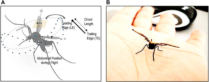
Figure 1. (A) Aerodynamic representation of mosquito during flight, mosquito-related flapping cycle phases, formation of leading and trailing edge vortices during phases of the wingbeat cycle of mosquito flight (Singh et al., 2021); (B) RoboMos, a mosquito-inspired FWPAV developed at UPM, Malaysia (Patented).
To achieve this, we embarked on a multi-step analysis, we studied the wing motion, employing quasi-steady aerodynamic modeling for a rigid wing model. This analysis involved deriving the equations of motion and investigating the forces acting on the robot during flight. Following linearization, we determined the stability and control derivatives to understand the robot’s behavior in flight. This analysis revealed the inherent instability of the design based solely on mosquito-mimicking kinematics. Given the stability limitations, we explored the implementation of a quasi-steady-based non-linear controller to examine control behavior and performance. Our research drew inspiration from established works in the field. The model by Sane and Dickinson (2002) (Sane and Dickinson, 2002) provided a foundation for understanding the forces involved, while the controller design adapted code developed by Karasek et al. (2012); Karásek (2014) for hummingbird flight, with significant modifications for insect-scale flight dynamics. It is important to note that while these references focused on real-life flying creatures, our work centers on a miniaturized robotic model.
This combined approach, encompassing kinematic analysis, aerodynamic modeling, stability assessment, and controller design, serves as a crucial preliminary assessment for the RoboMos project. The findings from this paper will pave the way for improved design, fabrication, and control strategies for this bio-inspired flapping-wing PAV.
Because of advances in Computational Fluid Dynamics (CFD), such as high-performance computing power, mathematical modeling of insect flapping flight has shifted from standard quasi-steady approximations to solving full-scale 3D Navier-Stokes equations for high-fidelity numerical studies. As mentioned in Section 1, CFD-based analysis is a promising tool. Still, its scope is limited in the case of insect flight due to the flow complexities associated with these creatures at such a low Reynolds number (Madangopal et al., 2005). It is highly unsteady. As a result, quasi-steady modeling aids in understanding the flow and calculating the forces and moments at the outset based on the given wing kinematics. The benefits of these models are that they can be easily incorporated into dynamic control models of these insects and can predict the energy and power requirements at the beginning, assisting in the design and development of insect robots (Madangopal et al., 2005).
Table 1 highlights the quasi-steady aerodynamic models developed from 1984 to 2022. It briefly mentions the type of forces included as part of the models for analysis. In this study, the wing morphology of an actual mosquito (Culex quinquefasciatus) found in peninsular Malaysia is used to design the PAV wing, as shown in Figures 2A, B and body in Figures 2C, D.
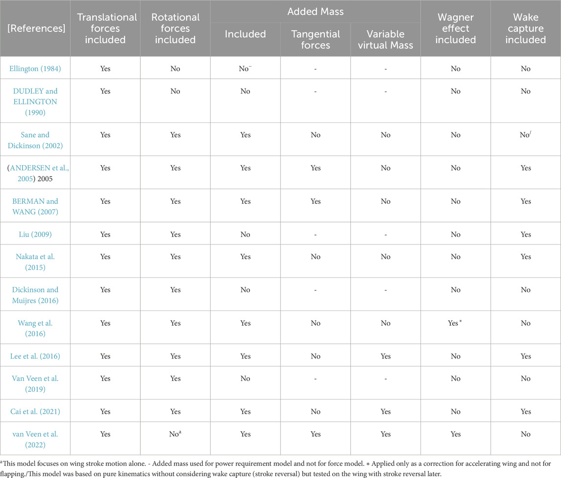
Table 1. Quasi-steady aerodynamic models were used to study the aerodynamics of flapping insect wings with mechanisms included (1984–2022). Reproduced with permission from (van Veen et al., 2022), Copyright 2022, The Cambridge University Press (UK).
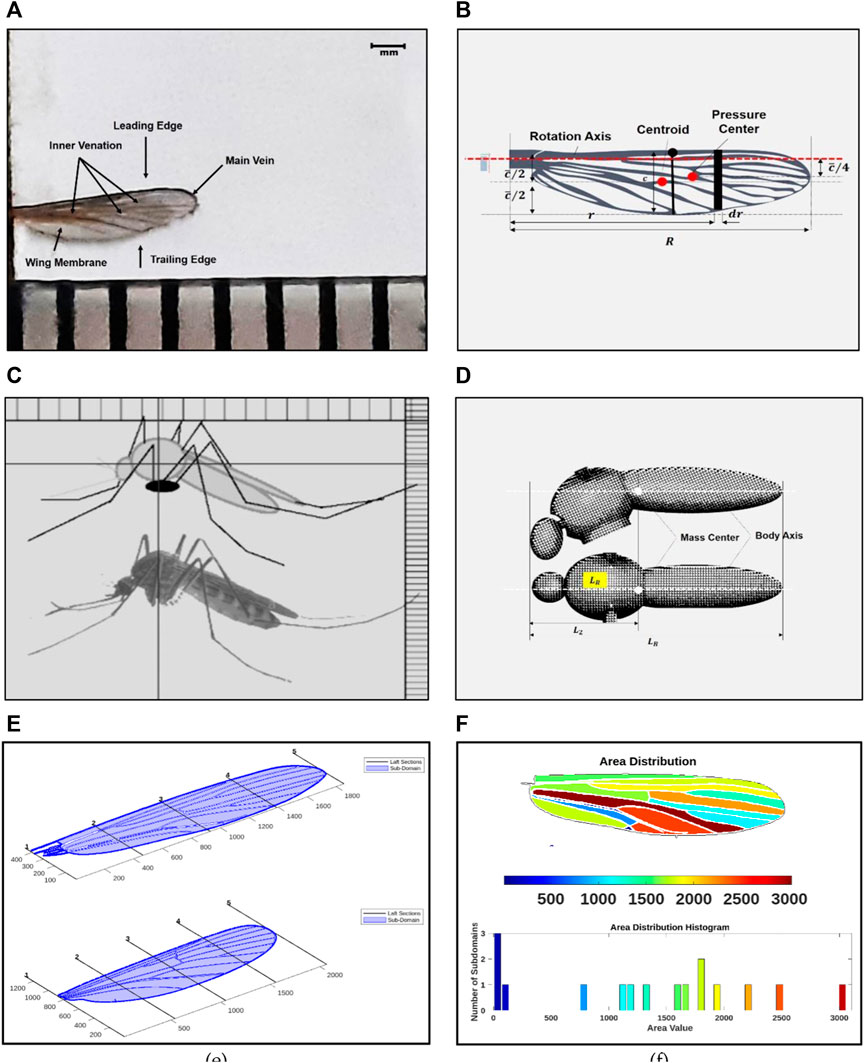
Figure 2. (A) Wing morphology including venation and corrugation of the real Culex quinquefasciatus wing; (B) Wing design modeled in design software and its geometric parameters (C) Body morphology of Culex quinquefasciatus; (D) Body design and geometric parameters of the PAV model (E) Morphology: Wing sample outline taking from real wing samples using computer vision (F) Wing area distribution and histogram given by the WingGram to understand the depth area.
The geometric positions, which include the position angles of all the veins, were marked with points. The wing corrugation is ignored here for the time being because it makes little difference to the aerodynamics of flight (Engels et al., 2020). WingGram developed by (Eshghi et al., 2022), a Matlab®-based open-source computer vision code, was used for initial wing modeling, as shown in Figures 2E, F. Following that, the mosquito wing and venation body were modeled in Autodesk® Fusion 360 (Cheng and Sun, 2016; Lee et al., 2016). Figure 2B shows the wing geometric parameters; standard definitions are taken from the reference (Ellington, 1984). According to the definitions and after carefully scaling the mosquito-inspired PAV model based on the requirement, material availability, actuation, and transmission-related constraints, the final model has the following morphological parameters: ∼
As described in the previous section, the morphological characteristics like wing to body ratio, body angle of the real mosquito were used from the morphology study done. The kinematic characteristics of the hovering mosquito like its wingbeat frequency and stroke amplitude used for this PAV are based on previous experimental studies (Bomphrey et al., 2017; Zhang and Huang, 2019; Liu et al., 2020). Because the wing-body interaction is negligible, the model is assumed to be rigid and static, and the deformation of the wings in the span-wise variation of the pitching angle (Zhang and Huang, 2019) is not considered for this preliminary study. Deformation or wing flexibility is essential for lift generation and will be considered in the model’s complete 3D computational analysis in the future.
The full kinematic model of the robot model is shown in Figure 3A, which includes the global coordinate system (
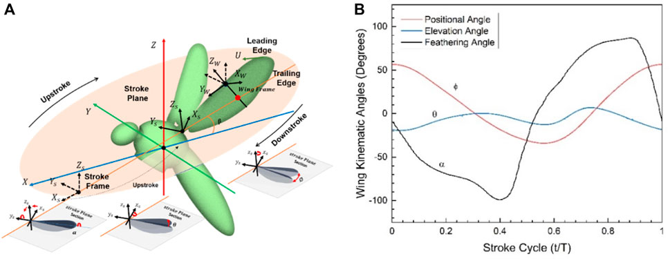
Figure 3. (A) PAV kinematic modeling and wing motion along the stroke plane; (B) General one full stroke cycle kinematics showing all the kinematic angles obtained by solving NS-equations; Positional (
Table 2 shows the wing kinematic parameters defined for this hovering PAV model. Previous literature reveals that mosquito wings are located above the mass center, an essential point for this analysis and for developing this mosquito-inspired PAV model. The position of the legs (spread or not spread) does not affect the center of mass but does affect the moment of inertia (Liu and Sun, 2019).
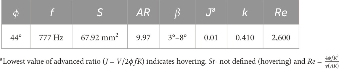
Table 2. Wing kinematic parameters as defined for this model in the hovering state.
Figures 4A, B show the minimum and maximum range of stroke amplitude for the mosquito model, which is very small, and Figures 4C, D show the variation of relative velocity
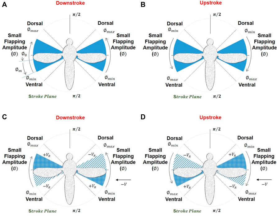
Figure 4. (A, B) Maximum and minimum stroke amplitude and the small amplitude angle the PAV possesses (C, D) variation in relative velocity during the downstroke and upstroke (stroke cycle) (top view). (+) sign indicates an increase and (−) for a decrease in relative velocity during the stroke cycle.
Due to the complexity and unsteady flow characteristics of insect wings, aerodynamic modeling methods continue to face significant difficulties and challenges. The authors of the reference (Xuan et al., 2020) provided a beautiful explanation of these models, stating their classification into three types: steady-state, quasi-steady, and unsteady. Steady-state models are simple and inappropriate for predicting load in small insects during flight. Quasi-steady models are good predictive models because they account for translational, rotational, and added mass forces and circulatory and non-circulatory components in all aerodynamics associated with these bio-creatures. Their output, however, differs slightly from that of computational fluid dynamics or experiments. Applying full-scale unsteady models to such complex flows necessitates additional research.
This paper employs a fundamental analysis of a mosquito-inspired PAV model, utilizing a simple quasi-steady approach rooted in the semi-empirical model developed by (Sane and Dickinson, 2002). In this analysis, the wing is considered to be rigid and flat, with the model grounded in blade element theory. Forces such as those arising from added mass and wake capture, as represented in Eqs 7, 8, are disregarded due to their minimal impact on overall force. Instead, the focus lies on pressure distribution-derived forces and their influence on movement, encompassing translation and rotation, as discussed by Karásek and Preumont (2012).
It is important to remember that the availability of appropriate flapping force coefficients from experimental data is critical to the success of a quasi-steady aerodynamic model (Nabawy and Crowther, 2014b). According to reference (Xuan et al., 2020), the total instantaneous force, therefore, can be expressed as:
According to reference (Deng et al., 2006; Karásek and Preumont, 2012), the total force is defined as components of the force in normal and tangential directions of the wing as in Eqs 9, 10:
Where
The PAV model dynamics are represented using a standard averaged model, and linearization is accomplished using the small perturbation method. The aerodynamic derivatives have also been calculated by simply solving the Navier-Stokes equations. There are also analytical ways to calculate the derivatives. Finally, the model’s stability properties are investigated at the hovering state at a very low Reynolds number.
Because the quasi-steady model is non-linear and the insect model is a time-variant dynamic system, the oscillating mass distribution and periodic aerodynamic and inertial forces associated with flapping wings can couple with the insect model’s natural modes of motion (Zhu et al., 2020). This coupled phenomenon can only be ignored or is unlikely to occur if the flapping frequency is extremely high, as with mosquitoes (Zhu et al., 2020). In this analysis, the forces are replaced with average flapping cycle forces, representing the model as a cycle-averaged model (Karásek and Preumont, 2012; Zhu et al., 2020). Therefore, the insect model is rigid in this analysis, and forces and moments are time-averaged over the flapping period.
The equations of motion (conservation of linear momentum equations CLMEs, conservation of angular momentum equations CAMEs, and kinematic equations are considered similar to that of an aircraft or helicopter and can be found in any standard book on flight dynamics and control like (Napolitano, 2011; Stevens et al., 2016). These equations in their non-linear form are related to the dynamic modeling of the body and wing of the mosquito-inspired PAV as shown in Figure 5 (Four frames of reference: earth-fixed (
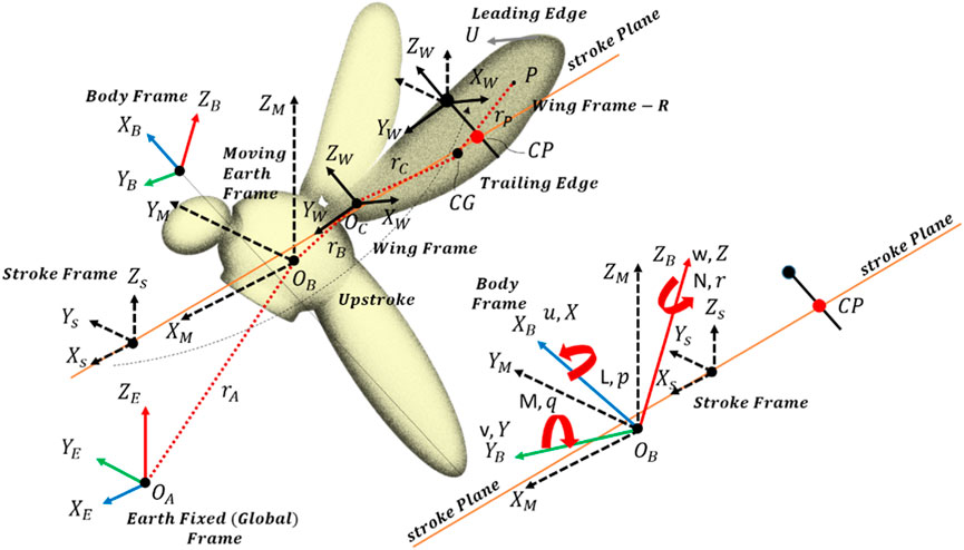
Figure 5. Dynamical modeling of the mosquito-inspired RoboMos PAV model.
The equations of motion given below for this flapping Pico aerial vehicle have been originally developed and presented by reference (Gebert et al., 2002) and error corrected by reference (Sun et al., 2007). The authors have used these general equations from the above references for this PAV as per their PAV dynamic model shown in Figure 5. The velocity for each frame is given in Eq. 12:
Where
Assuming a rigid body, Eqs 14,15 can be simplified further. Let
Where
Usually, for this PAV model, the
Using references (Gebert et al., 2002; Sun et al., 2007), given the assumption of a rigid body, the wing’s flapping frequency is notably high, resulting in a flapping motion time scale significantly shorter than that of the body’s motion. In the context of fluid dynamics, we can employ averaged forces, encompassing both aerodynamic and inertial forces, operating over the time scale of the body. By averaging Eqs 22, 23 over the flapping period to filter out rapid motions and capture the slower time scale, we derive Eqs 24, 25 as presented below:
Where
Eqs 26, 27 can now be utilized to determine the stability of this PAV model. For stability analysis, these CLMEs, CAMEs, and KEs must first be linearized using a small perturbation method for longitudinal and lateral motion. Figure 6 depicts the entire process.
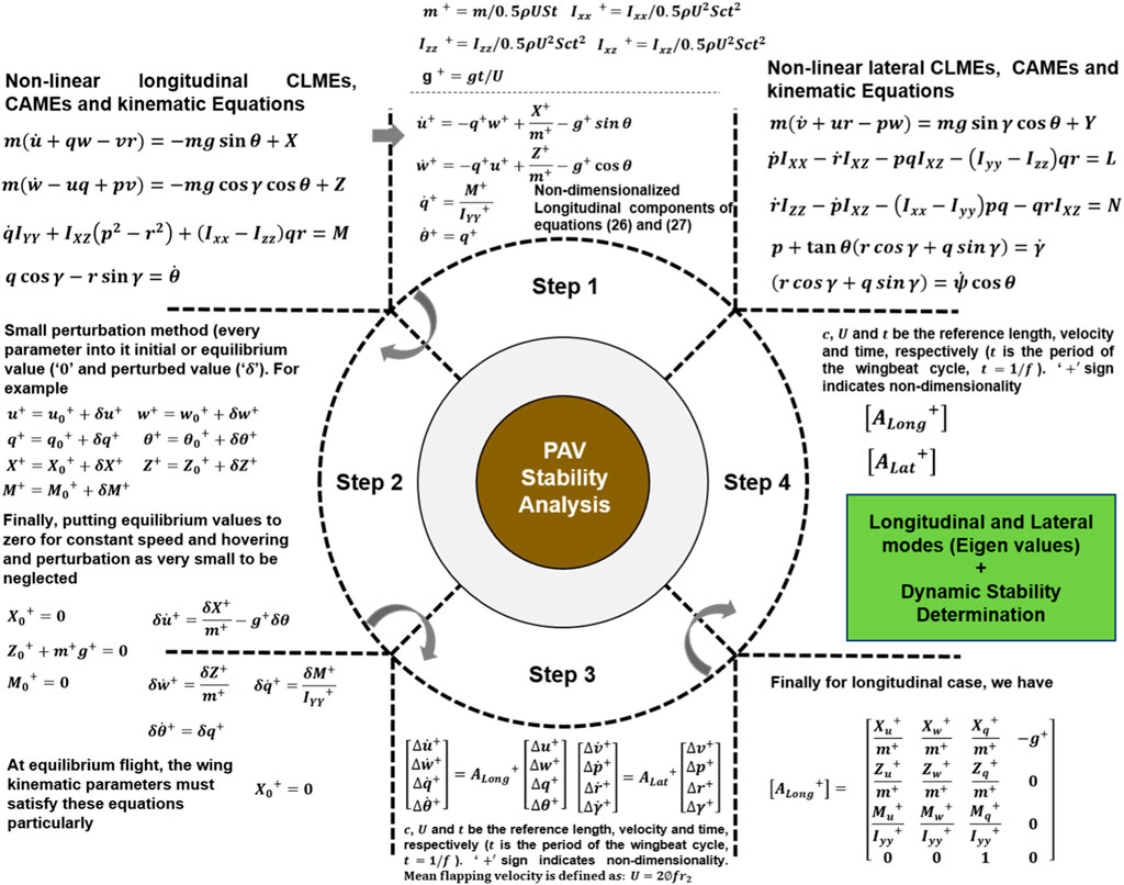
Figure 6. The general process of obtaining the longitudinal and lateral directional eigenvalues from system matrices is to get the system modes and determine the dynamic stability characteristics.
There are five essential points to note about the process displayed in Figure 6 and the approach used in this study. First, it is impossible to obtain system matrices in Eqs 28, 29 without total mass, moment of inertia, and stability derivatives. Second, wing kinematics are required to calculate stability derivatives, and morphological parameters (such as the position of the center of mass, the distribution of total mass, and the distance between the wing base and the center of mass) are required to calculate total mass and moments of inertia.
For this mosquito-inspired pico aerial vehicle model analysis, wing kinematics and morphological parameters are derived, taking reference from (Bomphrey et al., 2017; Liu and Sun, 2019), respectively. Third, the body’s position concerning the body frame of reference changes when the flight speed changes. As a result, the moment and product of inertia change as well. However, it is neglected here because of hovering conditions.
Fourth, to compute the stability and control derivatives, a common approach has been adopted for insects in many studies before, like in (Sun and Tang, 2002; Mou and Sun, 2012), references (Zhang and Sun, 2010; Karásek and Preumont, 2012; Liu and Sun, 2019; Zhu et al., 2020) and for Cranefly in reference (Xu et al., 2021), the description of which is not repeated here again. A simple immersed boundary method-based OpenFoam solver is used here for the relative motion of the wings and for calculating derivatives, followed by high-fidelity CFD analysis based on volume penalization (Engels et al., 2019).
In short, the methodology is to choose one parameter that varies around hover and keep the others in equilibrium. The cycle average forces and moments around each value are then calculated and plotted as a function of the parameter of interest. The linearity in the graphical results also justifies the linearization process used here, as shown in Figure 7A. The slopes of tangents in the origin to the curves obtained are the stability derivatives, as shown in Figure 7B. The control derivatives are also brought in the same way. Fifth, as stated at the outset of this section and from reference (Karásek and Preumont, 2012), it would be necessary to design a robot with symmetrical mass distribution around all three-body axes to avoid the coupling between motions in longitudinal and lateral cases. Stability derivatives can also be obtained using analytical methods, for example, a local averaging method (Orlowski and Girard, 2011). Table 3 shows the values obtained for each non-dimensional longitudinal and lateral dynamic stability derivative from this dynamics approach. Forces and moments of both wings and body are essential for getting derivatives in hovering flight, but body contribution can be neglected because of negligible velocity and minimal interaction between body and wings (Aono et al., 2008).
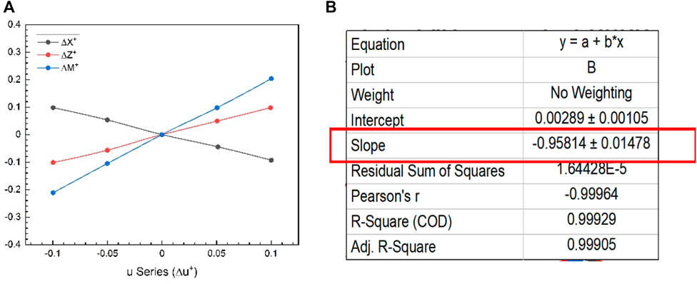
Figure 7. (A) Longitudinal stability derivatives from
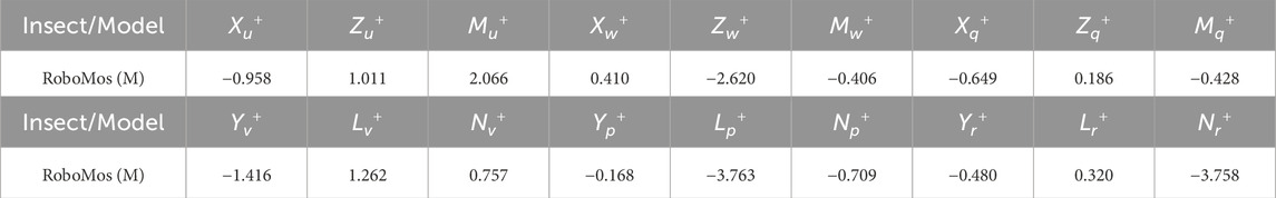
Table 3. Non-dimensional longitudinal and lateral stability derivatives for our model.
Aerodynamic forces and moments at various flight speeds can be calculated using kinematics at equilibrium flight. In general, at hover or even at very low velocity, these non-dimensional forces and moments
For this analysis, we followed the control strategy developed by (Karásek and Preumont, 2012; Karásek, 2014) and modified our code using their simple hummingbird model simulator with permission for our control simulation. In this instance, using a controller was not necessary as our primary focus was to analyze the inherent dynamic stability of the PAV model, without the influence of external control. So this is an additional analysis to check whether the controller performs well. As previously stated, the code from (Karásek and Preumont, 2012; Karásek, 2014) was taken as reference and controller was designed and utilized here using Matlab/Simulink®for insect flight analysis. Some notable features of their controller model are: 1. Decoupling the system into three subsystems (longitudinal, vertical, lateral + yaw) 2. The controller has two main loops: the inner one for attitude stabilization and the outer one for controlling velocities 3. Discrete type of design for cycle average forces and moments 4. Velocities controlled by PI controllers that need to be appropriately tuned. Figure 8 depicts the flowchart diagram of their controller scheme.
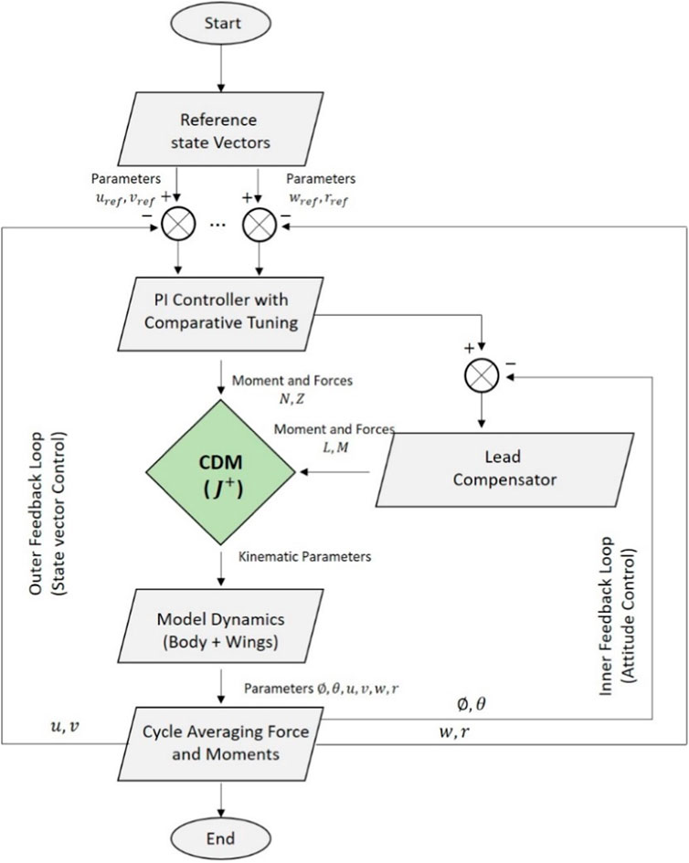
Figure 8. Controller flowchart for the simulator (Karásek and Preumont, 2012) with all the subsystems and control loops for velocity and attitude control.
It should be noted that the non-dimensional control derivative matrix is a critical component of this controller because it is responsible for converting or transforming the forces into the required wing motion. These control derivatives were obtained by us along with the stability derivatives using the same method described in the previous section and fed into the code. The sweep amplitude
Where
The feasibility of each choice’s wing control mechanism design will also constrain the final selection of control parameters in the real robot. The controller performance results from this control simulator modified for insect flight are sufficient for preliminary assessment before a detailed high-fidelity CFD analysis can be implemented. These findings and the excellent analytical calculations for dynamic stability of the linearized model presented in this paper aided in the initial design considerations.
Referring back to the dynamic stability analysis performed on the model as depicted in Sections 2, 3, the non-dimensionalized stability derivatives were then obtained, resulting in the construction of both the longitudinal and lateral system matrices as shown in Eqs 31, 32. A small 99-line Matlab®code was written to obtain the system matrices and the pole-zero plot from the data, observe the mode eigenvalue locations on the s-plane, and comment on stability.
The system matrices are further solved to obtain the eigenvalues and to identify the longitudinal and lateral dynamic modes. This aids in comprehending the model’s dynamic stability in the hovering state. Figure 10 depicts the pole-zero plot (s-plane) representing all the eigenvalues and dynamic modes. Figure 11 depicts the velocity magnitude of flapping PAV wings at high frequency with r/R = 0.5 (50% span) at different instants of one complete flapping cycle. The body motion is neglected because of the hovering. At hover, the increase in non-dimensional vertical force (
The numerical results in Figure 9 of the insect-inspired Pico Aerial Vehicle (PAV) flapping at high frequencies reveal promising outcomes. The heightened wingbeat frequencies, reminiscent of mosquito flight characteristics, contribute to unique aerodynamic effects. The aerodynamic analysis indicates the generation of trailing edge vortices through wake capture, reduced reliance on leading vortices, and the mitigation of rotational drag. In terms of energetics, the PAV’s performance during high-frequency flapping is noteworthy. The kinematic and quasi-steady aerodynamic modeling, considering translational, rotational, and wake capture forces, demonstrates efficient energy utilization. The adaptation of control strategies from bird flapping wings to insect wing kinematics proves effective, influencing the wing forces and providing a solid foundation for flight controller design.
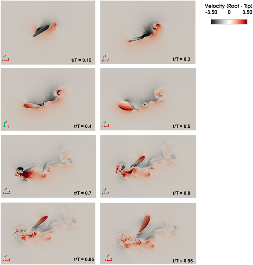
Figure 9. Velocity magnitude contours of the mosquito-inspired PAV wings flapping at high frequency (r/R = 0.5).
Dynamic stability analysis further underscores the favorable characteristics of the mosquito-inspired PAV during high-frequency flapping. Despite its small scale, the PAV exhibits a robust controller response, demonstrating excellent maneuverability. The modified model, incorporating rigid body dynamics and non-averaged aerodynamics, reveals weak stability without a controller or insufficient power density. However, the controller promptly stabilizes the PAV, ensuring its reliable performance in terms of attitude control and maneuverability. These inference results not only contribute to a deeper understanding of the aerodynamics and energetics of insect-inspired flapping-wing flight but also underscore the potential of such high-frequency flapping in enhancing the capabilities of Pico Aerial Vehicles for various applications.
At the equilibrium flight conditions, the aerodynamic forces and moments acting on the wings are computed for each of the parameters (
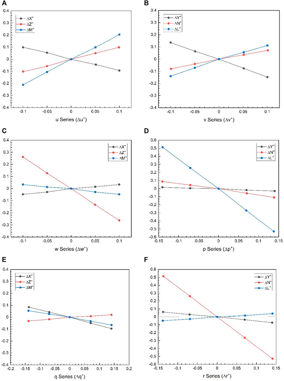
Figure 10. Time variations of the aerodynamic forces and moment of the wings in a flapping period including equilibrium flight; (A)
Figure 11 reveals that drag and lift show good convergence and typically represent the aerodynamic behavior of flapping wings. This is due to the same fact that the leading edge vortex is developed precisely at the beginning of the downstroke and intensifies to its maximum during the middle of the downstroke (t/T = 0.45), because of which there are peaks in the lift force. At the rotation point (t/T = 0.55) between the two strokes, the step rotation in the wings results in large peaks in the aerodynamic forces.
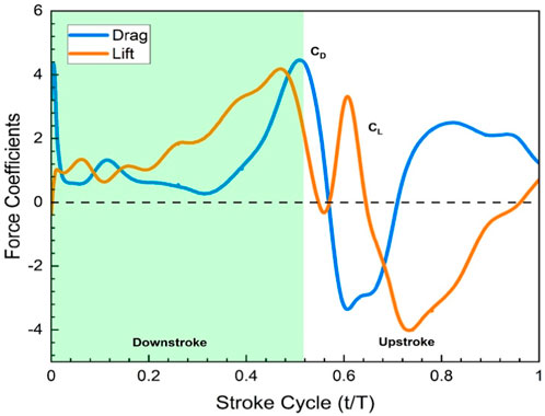
Figure 11. Force Coefficients
During the downstroke after pronation, the wing forms a trailing edge vortex (TEV), creating a negative pressure region that boosts lift. Subsequent strokes, including forward stroke with supination and upstroke after supination, involve both TEV and tip vortices, contributing to lift peaks. Positive pressure near the trailing edge of the ventral surface occurs separately, representing distinct mechanisms. Interestingly, the leading-edge vortex (LEV) negatively affects lift at the second peak, receding before supination. In contrast, TEV and tip vortices play key roles in the second lift peak. Throughout the downstroke, force and lift coefficient remain significant, with a dip at the second half of the upstroke.
At the hovering state (0 m/s), one unstable oscillatory dynamic motion mode with complex eigenvalues on the right half of the s-plane and two stable real modes with negative real eigenvalues on the left stable half of the s–plane have been observed. As a result, the mosquito-inspired PAV is weakly stable in longitudinal motion. Despite having stable oscillatory and subsidence modes, the model is also weakly stable in the lateral mode due to one of the positive real eigenvalues. This analysis demonstrates that the authors accurately captured the kinematics of real mosquitos for their PAV. Because of the weak stability in both the longitudinal and lateral cases, it is recommended that the PAV be built with an effective controller onboard or, to a minimum, an efficient actuation system capable of generating enough power density to lift off, hover, and counteract this effect. Figure 12 represents the stable and unstable eigenvalues plotted on an s-plane (pz map), clearly indicating instability in hover and a need for a controller. Tables 4, 5 show the eigenvalues obtained from this analysis and their comparability with eigenvalues from other studies for both longitudinal and lateral cases.
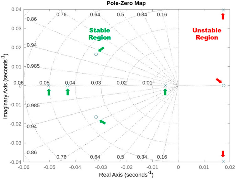
Figure 12. Representation of longitudinal and lateral eigenvalues with information about stable and unstable dynamic modes in 2D s-plane.
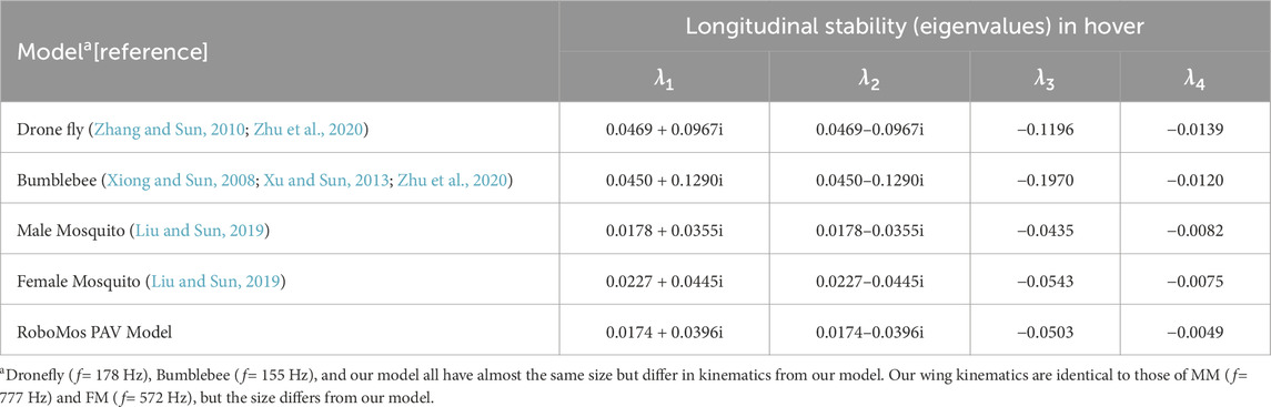
Table 4. Longitudinal stability modes (Eigenvalues from system matrices) in hovering.
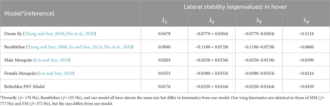
Table 5. Lateral stability modes (Eigen Values from system matrices) in hovering.
The results of modes in Tables 4, 5 also show greater consistency in terms of both longitudinal and lateral dynamic modes with previous studies and mode eigenvalues that are conventionally consistent with those of other real insects and models, even though they all have different flapping frequencies and amplitudes. In each case, stability derivatives govern these mode configurations.
It is interesting to note an important observation, which is not investigated here but shall be implemented experimentally for this model in the future. According to the reference (Liu and Sun, 2019), spreading the legs during the flight affects the moment of inertia but has a minor effect on the mosquito’s dynamic stability. Because the mosquito-inspired PAV developed in the laboratory has a detachable leg system, this observation will assist in carefully analyzing the flight in terms of stability during real-time flight tests and experiments in the wind tunnel.
The modified version of the model simulator with help from reference (Karásek and Preumont, 2012) used here in this study resulted in the evaluation of controller performance with step inputs, considering the state vectors
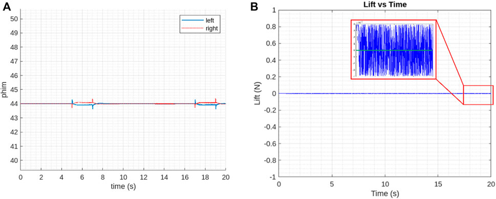
Figure 13. Controller performance (A) controlling factor, sweep amplitude
The generated vertical force is well controlled by the controller. The drift in its desired value at the end as shown in Figure 13B, might be due to the process of determination of control derivatives for CDM. This is in accordance with the trajectory that the PAV followed during hovering. However, the mean value of the parameters still closely follows the linear results with PAV kinematics.
The controller’s performance in the lateral direction behaves in the same way. Since the linearized dynamic analysis already gave good results, this preliminary controller performance assessment is enough to exhibit the need for a suitable controller.
Although the control parameters should be zero in hovering flight according to the linearized model, it is observed that sweep amplitude
Figures 14A, B show the controller performance in case of attitude and attitude rates. The interpretation of graphs shows slight differences between reference and generated results for controller performance in all angular rates and maneuvering that happens as vehicle reaches the hovering state and involves a thorough analysis of the magnitude, patterns, stability, and response time of these differences. This analysis helps in assessing the controller’s performance and guiding improvements to ensure that the system operates as close to the desired values as possible.
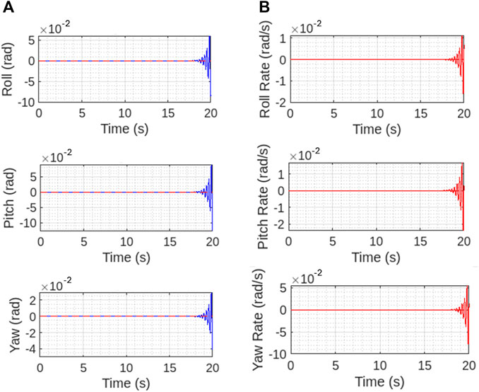
Figure 14. Controller performance for (A) maneuvering angles and (B) angular rates. The controller performance is well withing the reference till at the mid hovering state and controls the vehicle.
Figure 15 shows the desired trajectory that PAV follows during the take off and then hovering. As depicted the controller is well responsive during both the phases and keeps the vehicle balanced in hovering state implemented. Figure 16 shows the desired velocities in three directions with controller after some fine tuning. This clearly signifies that this insect inspired PAV can create complex wing trajectories using power and steering attached to the lifting surface and its actuation system. It is obvious that flight control such as stable hovering and trajectory tracking of actual fabricated PAV is a challenging task.
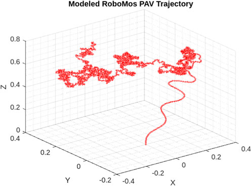
Figure 15. 3DRepresentation of RoboMos model trajectory from take off to hovering. Controller performance is depicted during the flight.
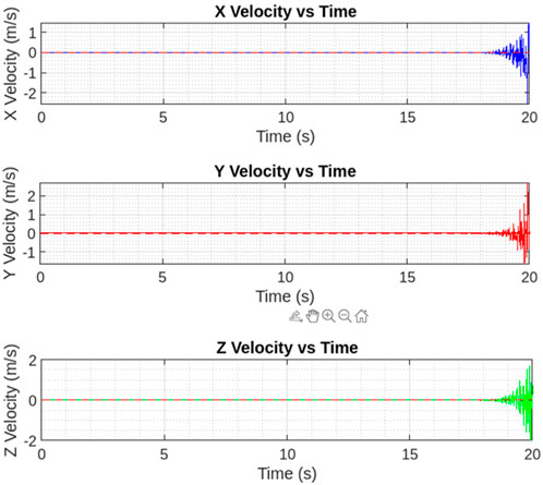
Figure 16. Three-dimensional velocity (state) plots. Again, the controller performance is well in accordance to the reference signal (red dashed).
The primary objective of this research was to conduct an initial assessment of the modeling, stability, and control aspects of RoboMos, a pico aerial vehicle prototype inspired by mosquitoes. The aim was to closely mimic the natural morphology and flight characteristics of actual mosquitoes. This analysis yielded valuable preliminary insights, encompassing mathematical modeling and control analysis. It precedes and helped with more detailed 3D computational analysis and the completion of the physical prototype for real-time flight testing. The key findings from this study are as follows:
• The pico aerial model closely resembles the natural structure and, to a large extent, the aerodynamics of a real Mosquito. In terms of longitudinal motion, it exhibits one unstable oscillatory mode and two stable subsidence modes. There is an unstable divergence mode, a stable oscillatory mode, and a stable subsidence mode for lateral motion.
• Despite several peculiarities in the aerodynamic mechanisms of mosquitoes, the major aerodynamic properties remain consistent.
• Due to the weak stability in both longitudinal and lateral motions, it is recommended that the PAV be equipped with an effective onboard controller or, at a minimum, an efficient actuation system capable of providing sufficient power density for takeoff, hovering, and counteracting instability.
• This analysis affirms that we accurately captured the kinematics of real mosquitoes in their PAV model. We hope that the fabricated RoboMos PAV will exhibit stable flight during real-time flight tests.
• The controller performance was thoroughly evaluated and it was found that vehicle attitude is controlled well by the controller during each phase of PAVs flapping flight.
The datasets presented in this article are not readily available because data can be acquired through an appropriate request. Requests to access the datasets should be directed to BS, YmFsYmlyLnNAbWFuaXBhbC5lZHU=.
The manuscript presents research on animals that do not require ethical approval for their study.
BS: Conceptualization, Data curation, Formal Analysis, Funding acquisition, Investigation, Methodology, Software, Validation, Visualization, Writing–original draft, Writing–review and editing. KA: Funding acquisition, Project administration, Supervision, Writing–review and editing. MM: Investigation, Methodology, Resources, Visualization, Writing–review and editing. NY: Project administration, Supervision, Validation, Writing–review and editing. AA: Project administration, Resources, Supervision, Validation, Writing–review and editing. RP: Project administration, Resources, Supervision, Validation, Writing–review and editing.
The author(s) declare that financial support was received for the research, authorship, and/or publication of this article. The authors gratefully acknowledge Universiti Putra Malaysia (UPM) for providing opportunities for biomimicry and soft robotics research to flourish and make this insect-inspired small aerial vehicle research a reality. The authors would also like to convey their gratitude to UPM to grant them the funding required to advance in biomimetic research through the Weststar Group (Tan Sri Syed Azman Endowment) industrial research grant; 6338204 – 10801.
The authors would like to thank and acknowledge the support of Universiti Putra Malaysia, Serdang for giving immense opportunity to do the research work based on this publication.
The authors declare that the research was conducted in the absence of any commercial or financial relationships that could be construed as a potential conflict of interest.
The author(s) declared that they were an editorial board member of Frontiers, at the time of submission. This had no impact on the peer review process and the final decision.
All claims expressed in this article are solely those of the authors and do not necessarily represent those of their affiliated organizations, or those of the publisher, the editors and the reviewers. Any product that may be evaluated in this article, or claim that may be made by its manufacturer, is not guaranteed or endorsed by the publisher.
Andersen, A., Pesavento, U., and Wang, Z. J.(2005). Unsteady aerodynamics of fluttering and tumbling plates. J. Fluid Mech. 541, 65. doi:10.1017/S002211200500594X
Aono, H., Liang, F., and Liu, H.(2008). Near- and far-field aerodynamics in insect hovering flight: an integrated computational study. J. Exp. Biol. 211, 239–257. doi:10.1242/jeb.008649
Berman, G. J., and Wang, Z. J.(2007). Energy-minimizing kinematics in hovering insect flight. J. Fluid Mech. 582, 153–168. doi:10.1017/S0022112007006209
Bomphrey, R. J., Nakata, T., Phillips, N., and Walker, S. M.(2017). Smart wing rotation and trailing-edge vortices enable high frequency mosquito flight. Nature 544, 92–95. doi:10.1038/nature21727
Cai, X., Kolomenskiy, D., Nakata, T., and Liu, H.(2021). A CFD data-driven aerodynamic model for fast and precise prediction of flapping aerodynamics in various flight velocities. J. Fluid Mech. 915, A114. doi:10.1017/jfm.2021.68
Cheng, X., and Sun, M.(2016). Wing-kinematics measurement and aerodynamics in a small insect in hovering flight. Sci. Rep. 6, 25706. doi:10.1038/srep25706
Deng, X., Schenato, L., Wu, W. C., and Sastry, S. S.(2006). Flapping flight for biomimetic robotic insects: part I-system modeling. IEEE Trans. Robot. 22, 776–788. doi:10.1109/TRO.2006.875480
Dickinson, M. H., and Muijres, F. T.(2016). The aerodynamics and control of free flight Manoeuvres in Drosophila. Philos. Trans. R. Soc. B Biol. Sci. 371, 20150388. doi:10.1098/rstb.2015.0388
Dudley, R., and Ellington, C. P.(1990). Mechanics of forward flight in bumblebees: I. Kinematics and morphology. J. Exp. Biol. 148, 19–52. doi:10.1242/jeb.148.1.19
Ellington, C. P.(1984). The aerodynamics of hovering insect flight. I. The quasi-steady analysis. Philos. Trans. R. Soc. Lond. B, Biol. Sci. 305, 1–15. doi:10.1098/rstb.1984.0049
Engels, T., Schneider, K., Reiss, J., and Farge, M.(2019). A wavelet-adaptive method for multiscale simulation of turbulent flows in flying insects. Available at: https://arxiv.org/abs/1912.05371.
Engels, T., Wehmann, H.-N., and Lehmann, F.-O.(2020). Three-dimensional wing structure attenuates aerodynamic efficiency in flapping fly wings. J. R. Soc. Interface 17(164), 20190804. doi:10.1098/rsif.2019.0804
Eshghi, S., Nabati, F., Shafaghi, S., Nooraeefar, V., Darvizeh, A., Gorb, S. N., et al. (2022). An image based application in Matlab for automated modelling and morphological analysis of insect wings. Sci. Rep. 12, 13917. doi:10.1038/s41598-022-17859-9
Gebert, G., Gallmeier, P., and Evers, J.(2002). “Equations of motion for flapping flight,” in AIAA Atmospheric Flight Mechanics Conference and Exhibit, Monterey, California, 5-8 August 2002. doi:10.2514/6.2002-4872
Harish Kumar, Y., Tripathi, U., and Singh, B.(2020). Design, mathematical modeling, and stability of a reconfigurable multirotor aerial vehicle. J. Aerosp. Eng. 33, 04019112. doi:10.1061/(ASCE)AS.1943-5525.0001102
Ishihara, D.(2022). Computational approach for the fluid-structure interaction design of insect-inspired micro flapping wings. Fluids 7, 26. doi:10.3390/fluids7010026
Karásek, M.(2014). Robotic hummingbird: design of a control mechanism for a hovering flapping wing micro air vehicle.
Karásek, M., and Preumont, A.(2012). Simulation of flight control of a hummingbird like robot near hover. Acta Tech. CSAV Ceskoslovensk Akad. Ved. 58.
Lee, Y. J., Lua, K. B., Lim, T. T., and Yeo, K. S.(2016). A quasi-steady aerodynamic model for flapping flight with improved adaptability. Bioinspir. Biomim. 11, 036005. doi:10.1088/1748-3190/11/3/036005
Liu, H.(2009). Integrated modeling of insect flight: from morphology, kinematics to aerodynamics. J. Comput. Phys. 228, 439–459. doi:10.1016/j.jcp.2008.09.020
Liu, L., and Sun, M.(2019). Dynamic flight stability of hovering mosquitoes. J. Theor. Biol. 464, 149–158. doi:10.1016/j.jtbi.2018.12.038
Liu, L. G., Du, G., and Sun, M.(2020). Aerodynamic-force production mechanisms in hovering mosquitoes. J. Fluid Mech. 898, A19. doi:10.1017/jfm.2020.386
Madangopal, R., Khan, Z. A., and Agrawal, S. K.(2005). Biologically inspired design of small flapping wing air vehicles using four-bar mechanisms and quasi-steady aerodynamics. J. Mech. Des. 127, 809–816. doi:10.1115/1.1899690
Mou, X., and Sun, M.(2012). Dynamic flight stability of a model hoverfly in inclined-stroke-plane hovering. J. Bionic Eng. 9, 294–303. doi:10.1016/S1672-6529(11)60123-6
Nabawy, M. R. A., and Crowthe, W. J.(2015). A quasi-steady lifting line theory for insect-like hovering flight. PLoS One 10, e0134972. doi:10.1371/journal.pone.0134972
Nabawy, M. R. A., and Crowther, W. J.(2014a). On the quasi-steady aerodynamics of normal hovering flight part II: model implementation and evaluation. J. R. Soc. Interface 11, 20131197. doi:10.1098/rsif.2013.1197
Nabawy, M. R. A., and Crowther, W. J.(2014b). On the quasi-steady aerodynamics of normal hovering flight part II: model implementation and evaluation. J. R. Soc. Interface. 11, 20131197. doi:10.1098/rsif.2013.1197
Nakata, T., Liu, H., and Bomphrey, R. J.(2015). A CFD-informed quasi-steady model of flapping-wing aerodynamics. J. Fluid Mech. 783, 323–343. doi:10.1017/jfm.2015.537
Nakata, T., Noda, R., and Liu, H.(2018). Fluid-structure interaction enhances the aerodynamic performance of flapping wings: a computational study. J. Biomech. Sci. Eng. 13, 17-00666. doi:10.1299/jbse.17-00666
Napolitano, M. R.(2011). Aircraft dynamics: from Modeling to simulation. First. New Jersey, United States: John Wiley and Sons, Inc. Available at: https://www.wiley.com/en-us/Aircraft+Dynamics%3A+From+Modeling+to+Simulation-p-9780470626672.
Orlowski, C. T., and Girard, A. R.(2011). “Stability derivatives for a flapping wing MAV in a hover condition using local averaging,” in Proceedings of the 2011 American Control Conference (IEEE), San Francisco, California, 29 June - 1 July 2011, 1604–1609. doi:10.1109/ACC.2011.5990862
Pohly, J., Salmon, J., Bluman, J., Nedunchezian, K., and Kang, C.(2018). Quasi-steady versus Navier–Stokes solutions of flapping wing aerodynamics. Fluids 3, 81. doi:10.3390/fluids3040081
Sane, S. P., and Dickinson, M. H.(2002). The aerodynamic effects of wing rotation and a revised quasi-steady model of flapping flight. J. Exp. Biol. 205, 1087–1096. doi:10.1242/jeb.205.8.1087
Singh, B., Yidris, N., Basri, A., Pai, R., and Ahmad, K.(2021). Study of mosquito aerodynamics for imitation as a small robot and flight in a low-density environment. Micromachines 12, 511. doi:10.3390/mi12050511
Stevens, B. L., Lewis, F. L., and Johnson, E. N.(2016). Aircraft control and simulation: dynamics, controls design, and autonomous systems. 3. New Jersey, United States: John Wiley and Sons, Inc.
Sun, M., and Tang, J.(2002). Unsteady aerodynamic force generation by a model fruit fly wing in flapping motion. J. Exp. Biol. 205, 55–70. doi:10.1242/jeb.205.1.55
Sun, M., Wang, J., and Xiong, Y.(2007). Dynamic flight stability of hovering insects. Acta Mech. Sin. xuebao. 23, 231–246. doi:10.1007/s10409-007-0068-3
Van Veen, W. G., Van Leeuwen, J. L., and Muijres, F. T.(2019). A chordwise offset of the wing-pitch axis enhances rotational aerodynamic forces on insect wings: a numerical study. J. R. Soc. Interface. 16, 20190118. doi:10.1098/rsif.2019.0118
van Veen, W. G., van Leeuwen, J. L., van Oudheusden, B. W., and Muijres, F. T.(2022). The unsteady aerodynamics of insect wings with rotational stroke accelerations, a systematic numerical study. J. Fluid Mech. 936, A3. doi:10.1017/jfm.2022.31
Wang, C., Zhang, W., Hu, J., Zhao, J., and Zou, Y.(2020). A modified quasisteady aerodynamic model for a sub-100 mg insect-inspired flapping-wing robot. Appl. Bionics Biomech. 2020, 1–12. doi:10.1155/2020/8850036
Wang, Q., Goosen, J. F. L., and van Keulen, F.(2016). A predictive quasi-steady model of aerodynamic loads on flapping wings. J. Fluid Mech. 800, 688–719. doi:10.1017/jfm.2016.413
Xiong, Y., and Sun, M.(2008). Dynamic flight stability of a bumblebee in forward flight. Acta Mech. Sin. 24, 25–36. doi:10.1007/s10409-007-0121-2
Xu, N., and Sun, M.(2013). Lateral dynamic flight stability of a model bumblebee in hovering and forward flight. J. Theor. Biol. 319, 102–115. doi:10.1016/j.jtbi.2012.11.033
Xu, N., Zhou, S., Zhang, C., and Mou, X.(2021). A computational study on lateral flight stability of the cranefly in hover. Comput. Model. Eng. Sci. 128, 669–685. doi:10.32604/cmes.2021.016269
Xuan, H., Hu, J., Yu, Y., and Zhang, J.(2020). Recent progress in aerodynamic modeling methods for flapping flight. AIP Adv. 10, 020701. doi:10.1063/1.5130900
Zhang, J. D., and Huang, W. X.(2019). On the role of vortical structures in aerodynamic performance of a hovering mosquito. Phys. Fluids. 31. doi:10.1063/1.5090878
Zhang, Y., Peng, Y., Cheng, Y., and Yu, H.(2020). A novel piezo-actuated flapping mechanism based on inertia drive. J. Intell. Mat. Syst. Struct. 31, 1782–1792. doi:10.1177/1045389X20935624
Zhang, Y., and Sun, M.(2010). Dynamic flight stability of a hovering model insect: lateral motion. Acta Mech. Sin. 26, 175–190. doi:10.1007/s10409-009-0303-1
Zhu, H. J., Meng, X. G., and Sun, M.(2020). Forward flight stability in a drone-fly. Sci. Rep. 10, 1975. doi:10.1038/s41598-020-58762-5
Keywords: flapping wing, pico aerial vehicle, trailing edge vortices, mosquitoes, quasi-steady modeling, flight control, kinematics, dynamic stability
Citation: Singh B, Ahmad KA, Murugaiah M, Yidris N, Basri AA and Pai R (2024) Quasi-steady aerodynamic modeling and dynamic stability of mosquito-inspired flapping wing pico aerial vehicle. Front. Robot. AI 11:1362206. doi: 10.3389/frobt.2024.1362206
Received: 27 December 2023; Accepted: 02 April 2024;
Published: 07 May 2024.
Edited by:
Hugo Rodrigue, Sungkyunkwan University, Republic of KoreaReviewed by:
Kyunam Kim, Sungkyunkwan University, Republic of KoreaCopyright © 2024 Singh, Ahmad, Murugaiah, Yidris, Basri and Pai. This is an open-access article distributed under the terms of the Creative Commons Attribution License (CC BY). The use, distribution or reproduction in other forums is permitted, provided the original author(s) and the copyright owner(s) are credited and that the original publication in this journal is cited, in accordance with accepted academic practice. No use, distribution or reproduction is permitted which does not comply with these terms.
*Correspondence: Kamarul Arifin Ahmad, YWVrYW1hcnVsQHVwbS5lZHUubXk=; Manikandan Murugaiah, bWFuaWthbmRuYW4ubUBtYW5pcGFsLmVkdQ==
Disclaimer: All claims expressed in this article are solely those of the authors and do not necessarily represent those of their affiliated organizations, or those of the publisher, the editors and the reviewers. Any product that may be evaluated in this article or claim that may be made by its manufacturer is not guaranteed or endorsed by the publisher.
Research integrity at Frontiers
Learn more about the work of our research integrity team to safeguard the quality of each article we publish.