 Jason Bettega
 Giovanni Boschetti
 Giulio Piva
 Dario Richiedei1
 Alberto Trevisani
- 1Department of Management and Engineering, University of Padova, Padua, Italy
- 2Department of Industrial Engineering, University of Padova, Padua, Italy
In Cable-Suspended Parallel Robots (CSPRs), reconfigurability, i.e., the possibility of modifying the position of the cable connection points on the base frame, is particularly interesting to investigate, since it paves the way for future industrial and service applications of CSPRs, where the base frame can also be replaced by mobile agents. This report focuses on fully actuated Translational Reconfigurable CSPRs (TR-CSPRs), i.e., reconfigurable CSPRs with a point mass end-effector driven by three cables. The objective of the work is twofold. First, it is shown that the Wrench Exertion Capability (WEC) performance index can be exploited to identify the configurations of the cable connection points optimizing a task-related performance in a single point or throughout the workspace, and hence to implement a workspace analysis. Then, by referring to the case of a TR-CSPR with a single reconfigurable connection point and in quasi-static working condition, an analytical approach is provided to reconfigure the robot while executing a task to avoid one of the paramount problems of cable robots: cable slackness. Brought together, the two contributions allow defining a reconfiguration strategy for TR-CSPRs. The strategy is presented by applying it to a numerical example of a TR-CSPR used for lifting and moving a load along a prescribed path: the use of the WEC allows analyzing the workspace and predicting if robot reconfigurability makes it possible to pass quasi-statically along all the points of a given path; then reconfigurability is exploited to avoid cable slackness along the path.
1 Introduction
1.1 State of the art
A Cable-Driven Parallel Robot (CDPR) is a parallel robot where the end-effector (EE) is actuated by cables whose lengths are set by winding them on motorized winches. Compared to classical parallel robots, CDPRs may present significant advantages, such as larger workspaces, higher dynamic performances, and higher payload capabilities. Moreover, cable winding systems are in general much cheaper to manufacture than the rigid links used as legs in parallel robots. These features make CDPRs interesting choices in industrial plants (Michelin et al., 2015), in telescoping operations (Nan et al., 2011), in urban mobility (Castelli et al., 2014), in home assistance (Merlet, 2008) and in human rehabilitation (Mao and Agrawal, 2011), just to mention a few representative field applications.
The number (n) and the layout of the cables reaching the EE of a CDPR considerably affect its performance. In order to fully or redundantly constrain the EE, it is required that n is at least greater by one than the number of the degrees of freedom (
Both in CDPRs and CSPRs, the possibility of modifying the configuration, meant as the position of the cable connection points on the base frame (also called exit-points), is particularly interesting, since it gives the possibility of significantly improving robot performances (Gagliardini et al., 2016a). The reconfiguration of the exit-points can be carried out in several ways, for instance by mobile agents (Jiang and Kumar, 2013; Masone et al., 2016; Six et al., 2017) and by mobile cranes (Nguyen et al., 2014) in Reconfigurable CSPRs (R-CSPRs), or through the reconfiguration of the whole base frame (Gagliardini et al., 2016b) in Reconfigurable CDPRs (R-CDPRs).
1.2 Aims of the paper
This work focuses the investigation on a spatial R-CSPR with a point mass EE (
The objective of this report, which introduces an opening study in this field, is twofold. First it is shown that the Wrench Exertion Capability (WEC) performance index proposed in (Boschetti and Trevisani, 2018) can be usefully exploited to identify the configuration of the exit-points which optimizes a task-related performance in a generic point of the robot workspace and, by iterating the investigation, to analyze the performance throughout the whole workspace. For sake of simplicity, but without loss of generality, the use of the WEC will be illustrated by considering a TR-CSPR with a single reconfigurable exit-point. Secondly, by assuming that the TR-CSPR operates in quasi-static conditions, the paper introduces an entirely analytical approach to reconfigure a single exit-point on-the-fly, while executing a task, avoiding one of the paramount problems of cable robots: cable slackness. It should be noted that the quasi-static working condition considered is quite popular in the case of R-CDPRs (see, for example (Gagliardini et al., 2016a)) and fits particularly well when CSPRs are used for handling heavy loads.
The analytical reconfiguration approach proposed, combined with the task-related workspace analysis based on the WEC, allow defining a reconfiguration strategy for TR-CSPRs which is then applied to an illustrative numerical example: a pick-and-place task imposing the reconfiguration of one exit-point. Such reconfiguration is assumed possible just along a given straight path (e.g., on a rail). First, the use of the WEC allows predicting if robot reconfigurability makes it possible to complete the task within the workspace; then reconfigurability is exploited to avoid cable slackness along the path.
This brief research report is structured as follows: the methodology section introduces the two combined contributions of the reconfiguration strategy: sub-Section 2.1 deals with WEC application to TR-CSPRs, sub-Section 2.2 deals with the analytical reconfiguration method. In Section 3 the achievements of sub-Section 2.1 and sub-Section 2.2 are combined to address the simulation of a representative pick-and-place task: the results are shown and discussed in the same Section, while concluding remarks are given in Section 4.
2 Methods
2.1 The wrench exertion capability index applied to TR-CSPRs
2.1.1 General formulation
A major advantage of reconfigurability is the possibility of modifying the workspace shape and the robot performances within it. Not only obstacles or cable collisions can be avoided (Gagliardini et al., 2016a) but robot key performances, such as the maximum payload or energy absorption, can be optimized. Indeed, the performances of a CDPR can be evaluated through several global or local indices that have been proposed in the literature (see, for example (Gouttefarde et al., 2007; Duan and Duan, 2014) and the references therein). By reconfiguring the exit-points of a R-CDPR, not only global but also local properties can be altered considerably to meet some desired requirements.
The capability of a TR-CSPR of balancing an external action (e.g., payload or environmental forces) is a relevant example of performance that can be optimized by reconfiguration. The WEC index proposed in (Boschetti and Trevisani, 2018) provides an evaluation of the maximum external wrench that the EE of a CDPR can bear along a given direction of interest and it is first applied here to TR-CSPRs.
The WEC is a local performance index that computes the maximum wrench component the cables can exert on the EE along a prescribed direction while maintaining assigned wrench components on the remaining directions and taking explicitly into account the lower (
For translational CDPRs, just forces rather than combined forces and torques (wrenches) are considered applied to the EE. Then, the general formulation presented in (Boschetti and Trevisani, 2018) can be applied straightforwardly to TR-CSPRs actuated by n cables converging in the EE, however, reconfigurability makes the optimization problem non-linear: the computation of the WEC index imposes the solution of a non-linear optimization problem where cable tensions and the Cartesian coordinates of the movable exit-points are the unknowns. Let identify the spatial directions of the cable forces by the unit vectors
Where
Through
Let
It can be recast as:
where the structure matrix
When the rotation matrix is employed, two additional orthogonal directions come along with d:
which consists in finding a and t that maximize the force exerted along the direction of interest d (
2.1.2 Example of WEC computation for a representative TR-CSPR
In this section, the general formulation of Eq. 6 is particularized for a three-cable TR-CSPR with a single reconfigurable exit-point. The TR-CSPR is shown in Figure 1I in a sample configuration, that is here discussed in detail: the EE, depicted as a black dot, has a mass
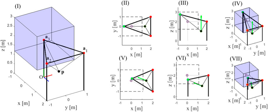
FIGURE 1. Nominal configuration of the TR-CSPR and optimal position of the reconfigurable exit-point for two different choices of the direction d of interest.
As a reasonable choice for this robot architecture, attention is paid to the maximum upward force that the cables can exert on the EE, the so-called WECz, while keeping null force components along the horizontal directions (
The non-convex optimization problem formulated in Eq. 7 imposes the use of global optimization routines to get rid of the presence of several local minima and hence to find the actual optimal solution (Richiedei et al., 2019; Belotti et al., 2020). In this work, the standard GlobalSearch routine of Matlab is used to generate the set of initial guesses through an efficient and reliable scatter-search algorithm, while the gradient-based, fmincon interior-point solver is used as the local solver.
The analysis of such a sample position leads to
Just to show how the optimal reconfiguration depends on the direction of interest, and hence on the task features, at the same position p of the EE the WEC is now computed considering another arbitrary direction
In general, by repeating the computation of the WECd at all the positions where equilibrium can be maintained by the EE, it is possible to perform a thorough task-related analysis of the performance achievable within the whole workspace. For example, the WECz analysis discussed above can be repeated in the Statically Feasible Workspace (SFW) of the TR-CSPR to analyze how the robot load-carrying capability changes as the EE changes position. The SFW is defined as the set of the EE poses for which static equilibrium against gravity can be obtained using a limited range of cable tensions (Trevisani, 2013). The results of such an analysis are shown in Figure 2: the three coordinates of the EE
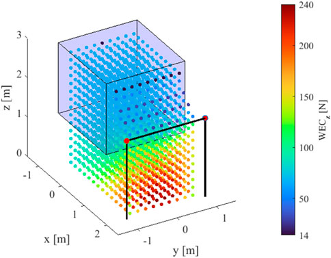
FIGURE 2. Results of a WECz-based workspace analysis.
The result of this analysis can be exploited to preliminary assess whether a task can be carried out in a part of interest of the workspace. For example, the possibility of moving quasi-statically a load can be easily verified through WECz: if the EE passes through positions where the WECz takes values greater than the load, there exists at least one configuration of the TR-CSPR which assures static equilibrium.
In the end, the WEC-based analysis appears useful to carry out preliminary investigations of task-related performances throughout the workspace, while it is not suitable to manage continuous exit-point reconfigurations for two reasons: firstly, the non-linear nature of the WEC formulation imposes a strong computational effort which is not compatible with real-time implementations; secondly, the optimal configurations computed in adjacent positions of the EE can differ significantly and could lead to discontinuous reconfigurations during the execution of a continuous displacement of the EE.
2.2 Reconfiguration method avoiding cable slackness
A method is therefore needed to reconfigure the exit-point continuously, while the EE is moving. In this section, by referring to the three-cable TR-CSPR with a single reconfigurable exit-point discussed above, and under the assumption that the TR-CSPR displaces a known load quasi-statically, an entirely analytical solution is proposed to move the exit-point continuously and to avoid cable slackness. This strategy still has some considerable limitations and lacks generality, but represents a first attempt to exploit continuous reconfigurability through an analytical and efficient strategy.
By assuming the static equilibrium of the EE
where
where
Since g and
with
If the positions of the EE and of the exit-points are known, the entries of
1. Keeping
2. Keeping
3. Setting
Other choices may be possible and would be worth of investigation. In particular, the first and the second constraints can be readily changed to define other directions along which the exit-point can be displaced. However, through this choice, the problem solution is straightforward:
o if
o if
o if
and
By knowing
3 Results and discussion
The test case proposed in this Section involves the three-cable TR-CSPR with a single reconfigurable exit-point assumed performing heavy handlings tasks in quasi-static motion, like a robotic crane in an industrial plant. The workspace analysis presented in sub-Section 2.1.2 and the reconfiguration method in sub-Section 2.2 are here combined to prove that they provide a reconfiguration strategy which allows completing the task while preserving positive cable tensions.
Figure 3 illustrates how the outcome of the WECz workspace analysis can be exploited to assess whether a desired path of the EE passes throughout feasible configurations of the robot. The advantage of such a workspace analysis is that it is valid regardless the mass that is intended to be lifted, whose change implies a modification of the external force in the z direction which can be straightforwardly compared to the WECz values computed along the path. Admittedly, if the task changed, and the resulting force one the EE was exerted along a different direction, the workspace analysis should be repeated. This should happen once at each task modification, but if the task does not change no WEC re-computation is needed.
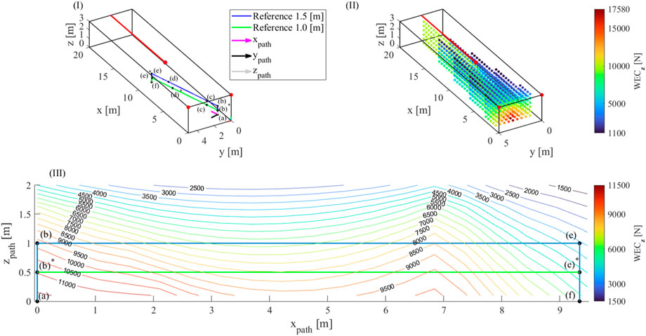
FIGURE 3. Representation of the considered paths (I), outcome of the WECz workspace analysis (II) and comparison among the desired paths and WECz values (III).
The base frame of the robot has a length of 20 m (axis x), a depth of 5 m (axis y) and a height of 3 m (axis z) and is sketched in Figure 3I. The mass of the EE of the robot, including the payload, is
The results of Figure 3II are exploited to assess if a desired path passes through positions where the WECz is greater than the downwards force acting on the EE. As an example, two different paths are analysed. The desired task concerns the displacement of a payload from a pick location
In order to evaluate each task, auxiliary reference frames (xpathypathzpath) are introduced (see Figure 3I with origin in (a) and axis xpath oriented along the segment from (a) to (f). In the first considered path, the payload is lifted up to 1.5 m from the grasp location: a three-dimensional representation of the path and a planar one in the xpathzpath-plane are shown in blue respectively in Figure 3I and Figure 3III. In the second considered path, the payload is lifted up to 1 m, as shown in green in Figure 3I and Figure 3III. Figure 3III is enriched with WECz isolines drawn in the xpathzpath-plane proving that the blue path is unfeasible, since, for example, at the position e), the maximum WECz that can be exerted by the robot is less than the EE weight or downwards component of
Let s be the curvilinear abscissa describing the displacement from (a) to (f) through all the via points. Figure 4 shows, on the left, the needed reconfiguration of the exit-point computed by the reconfiguration method in sub-Section 2.2, and, on the right, the cable tensions along the task, in both the cases that
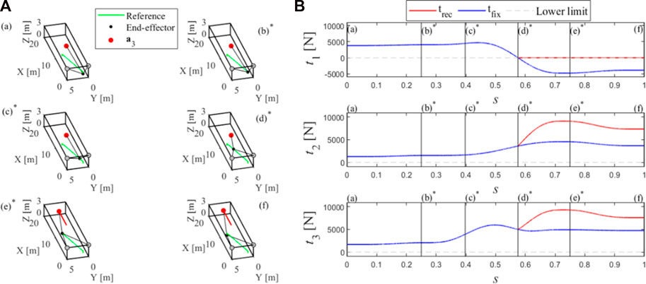
FIGURE 4. Reconfiguration of the exit-point (A) and cable tensions (B) along the path.
4 Conclusion and perspectives
This brief research report addresses two issues related to a fully actuated TR-CSPRs. First, it is shown that the WEC index can be successfully exploited to identify configurations of the exit-points optimizing task-related performances and to perform preliminary evaluations of the feasibility of given tasks within the workspace. Secondly, by focusing on a generic TR-CSPR actuated by three cables and with one reconfigurable exit-point which can be moved along a straight segment, it introduces an analytical reconfiguration method which can manage the displacement of the exit-point so as to assure positive tensions in all the cables during the whole task.
Clearly, an opening study is presented, but the use of the WEC for a preliminary evaluation of the workspace and of the feasibility of a task, combined with the implementation of an analytical approach capable of managing exit-point reconfiguration during task execution in a way which overtakes usual cable limitations, delineates an effective reconfiguration strategy for TR-CSPRs. The applicability of the strategy to more challenging R-CSPR topologies may not be trivial, in particular as far as the reconfiguration method is concerned, but certainly, worth investigating.
Data availability statement
The raw data supporting the conclusions of this article will be made available by the authors, without undue reservation.
Author contributions
All authors listed have made a substantial, direct, and intellectual contribution to the work and approved it for publication.
Funding
This research work is part of the Co-MIR PRIN 2020 project (Prot. 2020CMEFPK) funded by the Italian Ministry of University and Research (MUR).
Conflict of interest
The authors declare that the research was conducted in the absence of any commercial or financial relationships that could be construed as a potential conflict of interest.
Publisher’s note
All claims expressed in this article are solely those of the authors and do not necessarily represent those of their affiliated organizations, or those of the publisher, the editors and the reviewers. Any product that may be evaluated in this article, or claim that may be made by its manufacturer, is not guaranteed or endorsed by the publisher.
References
Belotti, R., Richiedei, D., and Tamellin, I. (2020). Antiresonance assignment in point and cross receptances for undamped vibrating systems. J. Mech. Des. 142 (2), 1. Transactions of the ASME. doi:10.1115/1.4044329
Boschetti, G., and Trevisani, A. (2018). Cable robot performance evaluation by Wrench exertion capability. Robotics 7, 15. doi:10.3390/robotics7020015
Bosscher, P., Williams, R. L., Bryson, L. S., and Castro-Lacouture, D. (2007). Cable-suspended robotic contour crafting system. Autom. Constr. 17, 45–55. doi:10.1016/j.autcon.2007.02.011
Castelli, G., Ottaviano, E., and Rea, P. (2014). A Cartesian Cable-Suspended Robot for improving end-users’ mobility in an urban environment. Robot. Comput. Integr. Manuf. 30, 335–343. doi:10.1016/J.RCIM.2013.11.001
Duan, Q. J., and Duan, X. (2014). Workspace classification and quantification calculations of cable-driven parallel robots. Adv. Mech. Eng. 6, 358727. doi:10.1155/2014/358727
Gagliardini, L., Caro, S., Gouttefarde, M., and Girin, A. (2016a). Discrete reconfiguration planning for cable-driven parallel robots. Mech. Mach. Theory 100, 313–337. doi:10.1016/j.mechmachtheory.2016.02.014
Gagliardini, L., Caro, S., Gouttefarde, M., and Girin, A. (2016b). Discrete reconfiguration planning for cable-driven parallel robots. Mech. Mach. Theory 100, 313–337. doi:10.1016/J.MECHMACHTHEORY.2016.02.014
Gouttefarde, M., Merlet, J.-P., and Daney, D. (2007). “Wrench-feasible workspace of parallel cable-driven mechanisms,” in Proceedings - IEEE International Conference on Robotics and Automation, Rome, Italy, 10-14 April 2007, 1492–1497. doi:10.1109/ROBOT.2007.363195
Idà, E., Bruckmann, T., Carricato, M., and Member, S. (2019). Rest-to-Rest trajectory planning for underactuated cable-driven parallel robots. IEEE Trans. Robotics 35, 1338–1351. doi:10.1109/TRO.2019.2931483
Jiang, Q., and Kumar, V. (2013). The inverse kinematics of cooperative transport with multiple aerial robots. IEEE Trans. Robotics 29, 136–145. doi:10.1109/TRO.2012.2218991
Mao, Y., and Agrawal, S. K. (2011). “A cable driven upper arm exoskeleton for upper extremity rehabilitation,” in 2011 IEEE International Conference on Robotics and Automation, Shanghai, China, 09-13 May 2011. doi:10.1109/ICRA.2011.5980142
Masone, C., Bülthoff, H. H., and Stegagno, P. (2016). “Cooperative transportation of a payload using quadrotors: A reconfigurable cable-driven parallel robot,” in IEEE International Conference on Intelligent Robots and Systems, Daejeon, Korea (South), 09-14 October 2016, 1623–1630. doi:10.1109/IROS.2016.7759262
Merlet, J.-P. (2008). “Kinematics of the wire-driven parallel robot MARIONET using linear actuators,” in Proceedings - IEEE International Conference on Robotics and Automation, Pasadena, CA, USA, 19-23 May 2008, 3857–3862. doi:10.1109/ROBOT.2008.4543803
Michelin, M., Baradat, C., Nguyen, D. Q., and Gouttefarde, M. (2015). Simulation and control with XDE and Matlab/Simulink of a cable-driven parallel robot (CoGiRo). Mech. Mach. Sci. 2015, 71–83. doi:10.1007/978-3-319-09489-2_6
Nan, R., Li, D., Jin, C., Wang, Q., Zhu, L., Zhu, W., et al. (2011). The five-hundred-meter Aperture Spherical radio Telescope (FAST) project. Int. J. Mod. Phys. D 20, 989–1024. doi:10.1142/S0218271811019335
Nguyen, D. Q., Gouttefarde, M., Company, O., and Pierrot, F. (2014). “On the analysis of large-dimension reconfigurable suspended cable-driven parallel robots,” in Proceedings - IEEE International Conference on Robotics and Automation, Hong Kong, China, 31 May 2014 - 07 June 2014. doi:10.1109/ICRA.2014.6907701
Richiedei, D., Tamellin, I., and Trevisani, A. (2019). A general approach for antiresonance assignment in undamped vibrating systems exploiting auxiliary systems. Mech. Mach. Sci. 73, 4085–4094. doi:10.1007/978-3-030-20131-9_407
Six, D., Chriette, A., Briot, S., and Martinet, P. (2017). Dynamic modeling and trajectory tracking controller of a novel flying parallel robot. IFAC-PapersOnLine 50, 2241–2246. doi:10.1016/j.ifacol.2017.08.183
Trevisani, A. (2013). Planning of dynamically feasible trajectories for translational, planar, and underconstrained cable-driven robots. J. Syst. Sci. Complex 26, 695–717. doi:10.1007/s11424-013-3175-1
Keywords: cable-driven parallel robots, cable-suspended parallel robots, reconfigurability, reconfiguration strategy, wrench exertion capability
Citation: Bettega J, Boschetti G, Piva G, Richiedei D and Trevisani A (2023) Reconfiguration strategy for fully actuated translational cable-suspended parallel robots. Front. Robot. AI 10:1112856. doi: 10.3389/frobt.2023.1112856
Received: 30 November 2022; Accepted: 19 January 2023;
Published: 06 February 2023.
Edited by:
Sébastien Briot, UMR6004 Laboratoire des Sciences du Numérique à Nantes (LS2N), FranceReviewed by:
Marc Arsenault, Laurentian University, CanadaAlessandro Gasparetto, University of Udine, Italy
Copyright © 2023 Bettega, Boschetti, Piva, Richiedei and Trevisani. This is an open-access article distributed under the terms of the Creative Commons Attribution License (CC BY). The use, distribution or reproduction in other forums is permitted, provided the original author(s) and the copyright owner(s) are credited and that the original publication in this journal is cited, in accordance with accepted academic practice. No use, distribution or reproduction is permitted which does not comply with these terms.
*Correspondence: Alberto Trevisani, YWxiZXJ0by50cmV2aXNhbmlAdW5pcGQuaXQ=