 Ung Hyun Ko1†
 Shyni Varghese
94% of researchers rate our articles as excellent or good
Learn more about the work of our research integrity team to safeguard the quality of each article we publish.
Find out more
ORIGINAL RESEARCH article
Front. Robot. AI, 19 September 2022
Sec. Soft Robotics
Volume 9 - 2022 | https://doi.org/10.3389/frobt.2022.991748
The emerging field of soft robotics often relies on soft actuators powered by pressurized fluids to obtain a variety of movements. Strategic incorporation of soft actuators can greatly increase the degree of freedom of soft robots thereby bestowing them with a range of movements. Balloon actuators are extensively used to achieve various motions such as bending, twisting, and expanding. A detailed understanding of how material properties and architectural designs of balloon actuators influence their motions will greatly enable the application of these soft actuators. In this study, we developed a framework involving experimental and theoretical analyses, including computational analysis, delineating material and geometrical parameters of balloon actuators to their bending motions. Furthermore, we provide a simple analytical model to predict and control the degree of bending of these actuators. The described analytical tool could be used to predict the actuating function of balloon actuators and thereby help generate optimal actuators for functions which require control over the extent and direction of actuation.
Unlike conventional robotics, soft robots are composed of highly compliant materials. The physical characteristics of soft robots allow passive interaction with surroundings to conduct delicate tasks in situations where classic/hard robots might fail, such as in medical assistance, irregular object investigation, and active prosthetics such as grippers (Cianchetti et al., 2018; Schmitt et al., 2018; Shintake et al., 2018; Whitesides, 2018; Jin et al., 2020; Zaidi et al., 2021). Pressurized balloon actuators have emerged as an attractive alternative to electronic-assisted actuators and are increasingly being used to control movements of soft robots (El-Atab et al., 2020). A typical balloon actuator is made of silicone elastomers containing chamber(s) which can be filled with fluids. Introduction of the fluid inflates the chamber, and the expansion pressure generated within the chamber leads to movement of the body resulting in large and fast deformation. Classification of soft actuators and design strategies to achieve different types of actuations have been reviewed in detail (Gorissen et al., 2017; Pagoli et al., 2021; Xavier et al., 2022). Balloon actuators are designed to undergo various movements such as expansion, contraction, twisting, and bending (Fujiwara et al., 2009; Marchese et al., 2015; Schaffner et al., 2018; Balak and Mazumdar, 2020). All of these motions are used at varying extents to endow soft robots with the desired actuation where the type of motion is largely controlled by architectural/geometrical features. For example, the expansion type balloon actuator in one of its design utilizes a bellows-like pattern with cylindrical fluidic channels which is designed to generate rapid linear elongation by concentrating the changes in volume in one direction (Dämmer et al., 2021; Hashem et al., 2021). This type of motion has been utilized in a ring-shaped robot gripper and in an endoscope stabilizer (Gorissen et al., 2018; Schreiber and Manns, 2021). The contracting type of balloon actuator produces axial shortening using radial expansion of the fluid chamber (Dang et al., 2019). This contraction movement generates axial force that can sustain a large magnitude of load and is utilized as an artificial muscle of a soft robot (Verrelst et al., 2005). To achieve twisting type motion, spiral constraints were incorporated within the structure which induces twisting movements of the elastomer body when the chamber inflates (Yan et al., 2018; Hu and Alici, 2020). Surakusumah et al. knitted the balloon actuator with a braided fibrous mat to create a twisting motion and utilized it to control the motion of bronchoscope for crawling the trachea and branches (Surakusumah et al., 2014).
The bending type balloon actuator utilizes a design that has an asymmetric structure involving one or more elastomers (Gorissen et al., 2011; Gorissen et al., 2017). In their simplest form they consist of a single chamber with walls of varying compliances (Xavier et al., 2021). When the chamber is pressurized, expansion occurs on the side with a wall of higher compliance. Upon inflation, the expansion of the balloon structure results in bending force. This bending force produces rapid movement, implementing many types of nature-inspired motions in soft-robotic devices such as those of octopus (Wehner et al., 2016), spider (Ranzani et al., 2018), dragonfly (Kumar et al., 2021), and human finger (Lu and Kim, 2003; Jeong et al., 2005; Kim and Cha, 2020). Various strategies can be used to vary the wall compliance such as changing the geometry, using different materials, or incorporating constraints such as inextensible fibers (fiber-reinforced bending actuators) (Polygerinos et al., 2015). By connecting multiple bending balloon actuators in series, advanced functionalities such as gripping and locomotion can been achieved (Shepherd et al., 2011; Zolfagharian et al., 2020; Pagoli et al., 2021). Most of the balloon actuator assisted soft robotics are focused largely on the type of movement. However, given the relationship between the material and geometrical properties of bending balloon actuator and its actuation, models that can describe and predict the performance of the actuators will expand their applications.
Various models describing the behavior of bending actuators have been reported. Among the analytical models, the Euler–Bernoulli beam theory is the most widely adapted and it treats the bending actuators as ideal beams loaded with moment at its edge and counteracted with the bending stiffness of the beam (Gorissen et al., 2011; Gorissen et al., 2017). However, several limitations of this model have been reported such as its inapplicability at large deformations, inaccuracy due to changes in beam cross-sectional area during actuation, and its use of Young’s modulus, which is not sufficient to capture the complex stress-strain behavior of hyperelastic materials (Gorissen et al., 2017). Coupling of non-linear finite element method (FEM) solvers with hyperelastic material properties have been used to model complex behavior of soft actuators (Gorissen et al., 2017). However, incorrect use of material properties (approximating from literature) can compromise the accuracy of the results (Gorissen et al., 2017; Xavier et al., 2021). Additionally, very few dynamic FEM models of bending actuators have been reported with most models incorporating a fixed load to the actuator and performing a static/quasi-static simulation (Xavier et al., 2021). In this study, we used a single microchannel-based hydraulic bending actuator, a system widely adapted in small-scale soft robotics, to assess the effect of material properties and geometry on bending motion. By using experimentally determined material properties, we performed dynamic FEM analyses to model the bending of the actuator with response to increasing pressure generated by the fluid flow into the microchannel. The bending angle of the balloon actuator with various geometries was characterized as a function of fluidic pressure. In addition, we also varied the mechanical properties of the material used to fabricate different components of the balloon actuator to determine their role on actuation. The computational model was validated experimentally, and a simple analytical model has been proposed to describe the extent of bending of the actuators as a function of fluidic pressure.
The balloon actuator was prepared by plasma bonding of two independent elastomeric bodies—body A and body B—with different mechanical properties and dimensions. The elastomeric body A contained a microchannel connected to a rectangular chamber whose length was varied to create balloons with different expansion area. The microchannel was designed as a straight channel with dimensions of 0.5 mm
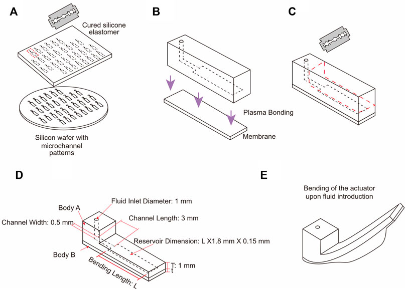
FIGURE 1. Schematic depicting the process of balloon actuator fabrication. (A) Silicon wafers patterned with microchannels were used as molds for soft lithography of Body A. (B) Inlet was punched into Body A which was then bonded to Body B (membrane prepared using spin coating) using oxygen plasma (C) Body A was trimmed to maintain a thickness of 1 mm over the microchannel of all actuators. (D) Dimensions of different parts of the actuator. (E) Bending of the actuator upon fluid introduction.
Hyperelastic material properties of PDMS were determined by uniaxial tensile testing using ElectroForce 3220 Series III (TA Instruments, Inc.). The ASTM (American Society for Testing Materials) Type V dumbbell specimen of 4 mm thickness was used with a 225 N load cell. The stress-strain measurements were carried out at 0.25 mm/min strain rate. A stress-strain curve was fitted using a two-term Ogden model (Eq. 1) to acquire the Ogden parameters.
Where, λ is the principle stretch and α1, α2, μ1, and μ2 are material constants.
The Ogden parameters
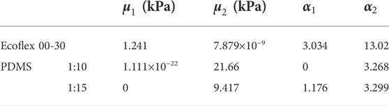
TABLE 1. Two-term Ogden parameters of Ecoflex 00-30, and PDMS with 1:10, 1:15 ratio of base to curing agent.
3D numerical simulations using COMSOL 5.3a or 5.5 were performed to characterize the balloon actuator bending angle with different chamber dimensions and mechanical properties. The balloon actuator developed in the simulation was composed of a flexible body (similar to body A) and an expandable membrane (similar to body B). The flexible body and expandable membrane dimensions were designed to be 3 mm width
Fluid domain (Inside the chamber):
Inlet: volume flow rate
All other walls: no slip with
Initial conditions:
Solid domain (flexible body and expandable membrane):
Right ends:
All other outer boundaries: free boundaries and zero stress.
Initial conditions:
The moving mesh was applied for the fluid domain, and the physics of the fluid domain were calculated using the laminar flow module. The physics of the solid domain were solved using a solid mechanics module with the experimentally obtained Ogden parameters. The fluid-structure interaction was applied to the coupled interfaces between the fluid and solid domain. All other estimated values of physical parameters are summarized in Supplementary Table S1 and a detailed COMSOL report is provided in Supplementary Information.
To experimentally validate the COMSOL simulation findings of the bending movement, various balloon actuators were prepared. Experiments were carried out to investigate differences in bending motion as a result of changes in chamber length, membrane thickness, and body/membrane materials with different mechanical properties. The experimental groups are summarized in Table 2.
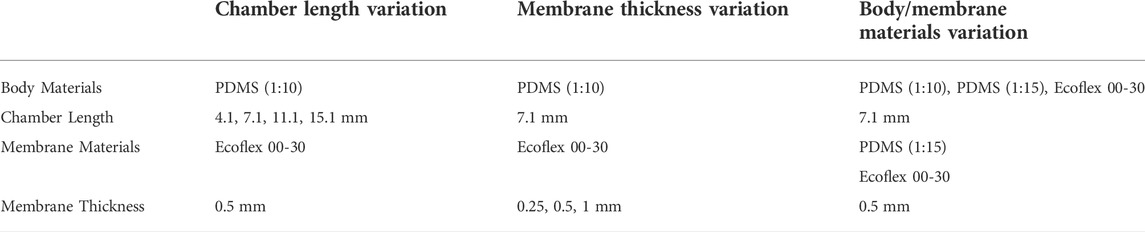
TABLE 2. Balloon actuator design for each experimental group.
The balloon expansion was enabled using a syringe pump (Harvard Apparatus, Inc.) with a fluid feeding at rate of 2.5 μl/s through a microchannel inlet. The corresponding actuations were video recorded for 10 s and quantified every 1 s using ImageJ software (ImageJ software, NIH) (Supplementary Figure S2).
The bending force of the balloon actuator was quantified by force equilibrium using a custom designed experimental approach. The balloon actuator and an elastomeric rubber band (6.35 cm
Where,
The bending motion of the balloon actuator was produced by an asymmetric deflection of the two silicone elastomer layers, that are bonded to each other, with differential mechanical properties and thicknesses. Figure 2A shows the schematic of the balloon actuator that was used for the theoretical and experimental analyses. When fluid is injected through a microfluidic channel, the expandable membrane (body B) is inflated by a hydraulic pressure, creating a balloon in the chamber. With the membrane expansion, the flexible body A is subjected to a hydraulic pressure from the fluid inside the balloon and a simultaneous pulling force from the elasticity of the membrane (i.e., body B) (Figure 2B). Gorissen et al. (Gorissen et al., 2011) demonstrated that the flexible body can be modeled as a cantilever beam, and by the Euler-Bernoulli beam equation, the bending curvature can be calculated as follows,
Where
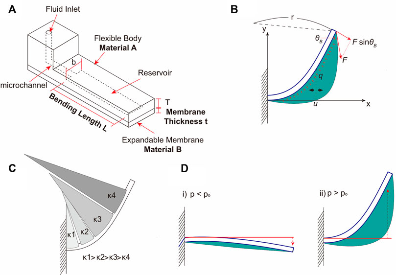
FIGURE 2. The design and working of balloon actuator. (A) Schematic of balloon actuator showing various components – Chamber length L, membrane thickness t, Materials A and B are the materials constituting the Body A and Body B, respectively. (B) Free body diagram of balloon actuator. The thick blue line indicates the flexible body, and the green area indicates the surface of the expandable membrane. Red arrows represent the forces acting on a flexible body. (C) Bending shape of the balloon actuator according to the change in curvature. (D) Illustration of two bending cases during membrane expansion. The bending direction of the body is decided by the degree of membrane expansion.
From Eq. 3 and Figure 2B, as the value of
where
It has been shown previously that when the balloon is small and the pressure inside the balloon is lower than a certain transition pressure, (p < po, with po being the transition pressure), the flexible body (i. e., body A) bends towards the balloon (Konishi et al., 2006; Gorissen et al., 2011). However, when the balloon is large and the transition pressure is exceeded (p > po), then the flexible body (i.e., body A) bends towards the opposite side of the balloon (Figure 2D). Herein, we focused on p > po for all experimental conditions because the expandable membrane (i.e., body B) inflates rapidly, and the duration of p < po can be considered negligible.
Balloon actuators with varying chamber lengths (L), 4.1, 5.1, 7.1, 9.1, 11.1, 13.1, 15.1, and 17.1 mm, were simulated to assess the bending angle changes. From the analyses, we have arbitrarily chosen a balloon actuator with 7.1 mm chamber length (L), 1 mm thickness of the body A (T), 0.5 mm thickness of the body B (t), and 1.8 mm chamber width (b) as a standard and compared against for all other experimental groups (Table 3).
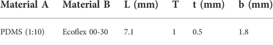
TABLE 3. Geometrical description and material composition of the balloon actuator that was set as the standard.
As suggested by the COMSOL solution, for a fixed pressure, increasing the chamber length resulted in an increased bending angle (Figure 3A). This is attributed to the increase in moment arm with increasing chamber length, which will result in greater moment and curvature (Eq. 3) at the same inflation pressure. Beyond a chamber length of 7.1 mm, an increase in input pressure had a smaller effect on bending angle. This is because with increasing chamber length more fluid is required to generate the same inflation pressure compared to chambers with lower chamber length, resulting in slower response. The simulation results were verified by experiments. As shown in Figure 3B, all the balloon actuators with varying chamber lengths showed similar bending behavior as the simulation.
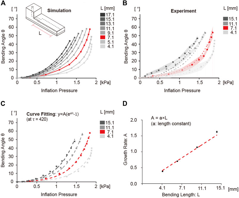
FIGURE 3. Simulation and experimental results of bending angle change as a function of chamber length. (A) Simulation plot showing the bending angle as a function of inflation pressure. The difference in the bending angle was confirmed by gradually increasing the chamber length from 4.1 to 17.1 mm. Curve for 7.1 mm shown in red was considered the standard control condition. (B) Experimental results of bending angle with 4.1, 7.1, 11.1, 15.1 mm chamber length. Dots indicate the average values of bending angle, and the shaded area represents the standard deviation of each data point. Dotted lines are the simulation results from (A). (C) Curve fitting analysis results using the exponential growth model. The dashed line indicates the fitting curve graph using estimated variables. (D) Change of amplification constant A according to change in bending length. The constant A showed a linearly increasing relationship with chamber length.
The curves of the bending angle with different inflation pressures were mathematically modeled to characterize the effect of chamber length on bending angle by using an exponential function (Eq. 5).
where
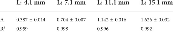
TABLE 4. The amplification constants
The pressure constant
The balloon actuators with varying membrane thickness of body B, 0.5, 0.75, or 1.0 mm, were simulated to assess its effect on bending angle. All variables except membrane thickness were fixed as the standard as described in Table 3. As expected, we found that thicker membranes required more pressure to generate the same bending angle compared to those with thinner membranes (Figure 4A); this resulted in a shifting of the bending curve along the x-axis as the membrane thickness increased. These results were verified experimentally, which showed the same trend with similar values (Figure 4B).
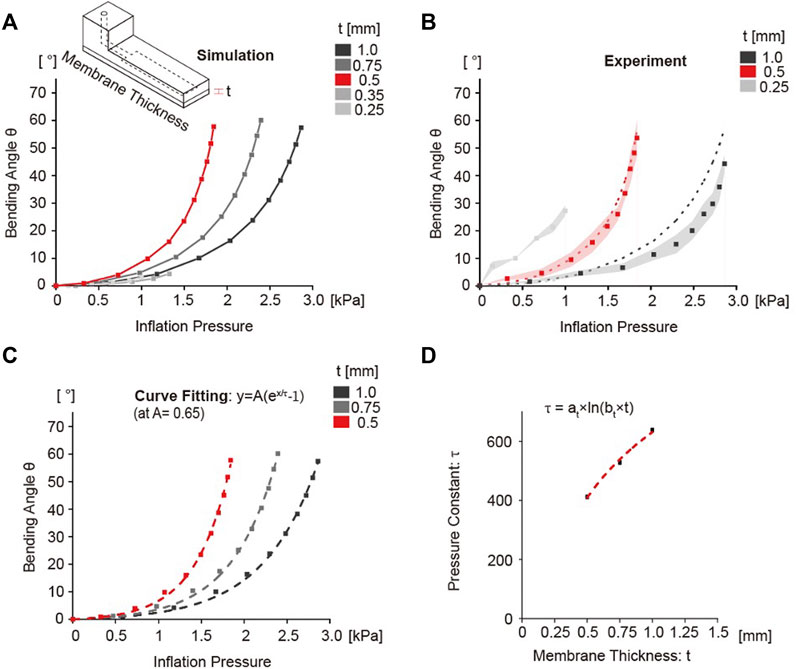
FIGURE 4. Simulation and experimental results of bending angle as a function of membrane thickness. (A) Simulation graph showing the bending angle as a function of inflation pressure change. The difference in the bending angle was confirmed by gradually increasing the membrane thickness from 0.25 to 1.0 mm. 0.5 mm curve shown in red was considered the standard control condition. (B) Experimental results of bending angle with 0.25, 0.5, 1.0 mm. Dots indicates the average values of bending angle, and the shaded area represented the standard deviation of each data point. Dotted lines are the simulation results from (A). (C) Curve fitting analysis results using the exponential growth model. The dashed line indicates the fitting curve graph using estimated variables. (D) Change of pressure constant τ according to change in membrane thickness. The constant τ showed a logarithmically increasing relationship with membrane thickness.
When the thickness of the membrane was decreased below 0.5 mm, the formation of a node in the middle of the chamber was observed and the expanded balloon separated into two smaller balloons. Corresponding experimental analyses validated the stimulation results (Supplementary Figure S4). This is likely due to inability of the thinner membranes to withstand large strains as the formation of two separate balloons results in smaller deformation. The balloon actuators with membrane thickness that leads to formation of two small balloons displayed minimal bending (Figure 4A). Furthermore, thinner membranes were also more vulnerable to ruptures during balloon expansion. Balloon actuators exhibiting this phenomenon could compromise functionality when used in soft robotics. Hence, we used 0.5 mm as the lower limit for the membrane thickness and further analysis was performed only for membrane thickness >0.5 mm.
The simulation data for various membrane thicknesses were fitted by using an exponential growth function with the fixed amplification constant A of 0.65 (Figure 4C). The initial value of A was estimated from the exponential function curve fitting of the standard without any constraints. From the results, the pressure constants
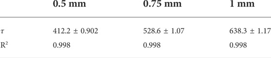
TABLE 5. The pressure constant
The pressure constant
where t is the thickness of the membrane.
The at and bt values for the curve in Figure 4D were 731.2 ± 57.11 and 7.179 ± 0.896, respectively, with an R2 of 0.988. In contrast, if
Next, we studied the role of mechanical properties in determining the bending actuation. We tested various combination of materials A and B for the two layers of the balloon actuator. Among the two layers, it is the softer layer that inflates and forms the balloon. This expansion causes the direction of expansion force Fexp to induce an asymmetric bending towards the stiffer layer side (Figure 5A). This control over direction was verified experimentally (Figure 5B). If PDMS (1:10) and Ecoflex 00-30 were used for Material A and B for body A and B, respectively, the bending occurred toward Material A (PDMS 1:10). In contrast, if Ecoflex 00-30 and PDMS (1:15) were used as Material A and B for body A and B, respectively, the bending occurred towards Material B (PDMS 1:15). The Young’s moduli of PDMS (1:10), PDMS (1:15) and Ecoflex are approximately 2 MPa, 1 MPa and 0.125 MPa respectively (Park et al., 2010; Wang et al., 2014; Shintake et al., 2017).
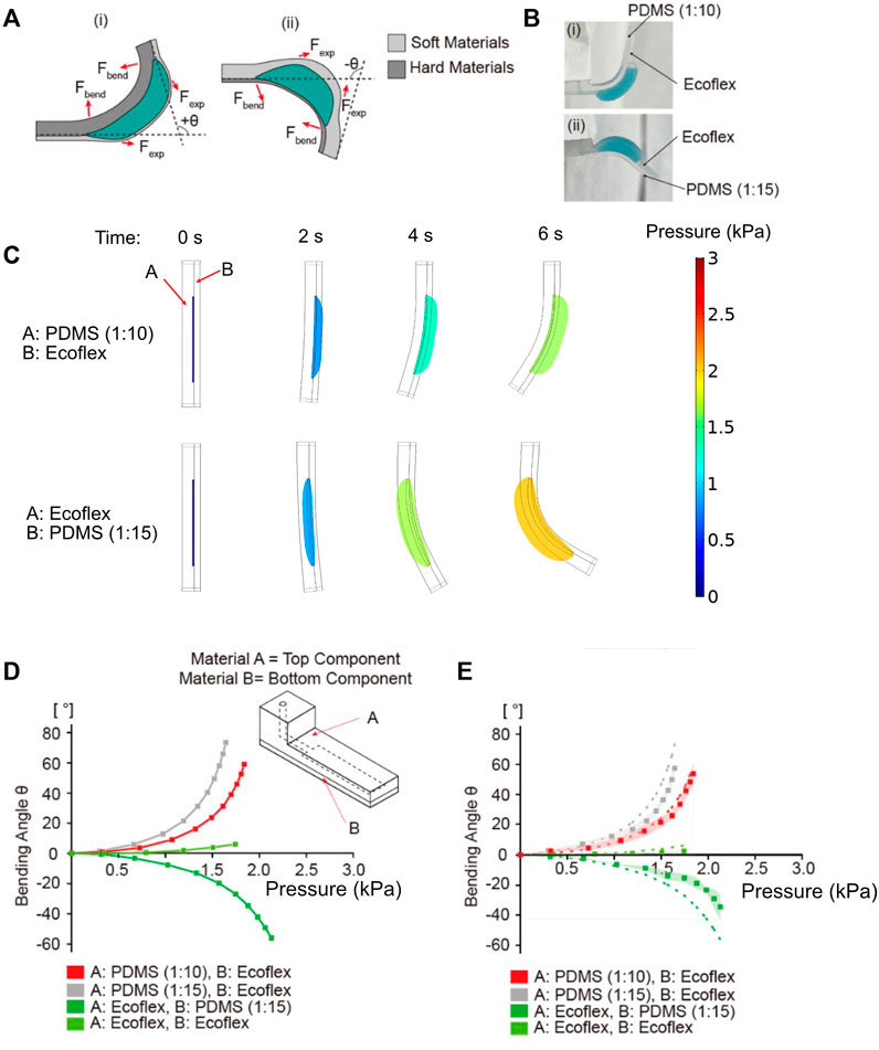
FIGURE 5. Simulation and experimental results for bending angle dependence on the materials A and B. (A) Change in bending motion due to difference in stiffness of materials A and B. (B) The experimental results of bending motion according to the stiffness of materials A and B: (i) When material B (expandable membrane) was softer than material A, the balloon actuator bent upwards and (ii) when material A was softer than material B, the flexible body (material A) underwent balloon expansion, causing reversed bending downward. (C) Images from COMSOL results showing the shape of actuators and the generated pressure at different time points. (D) Simulation results showing the bending angle as a function of inflation pressure. Various materials A and B of balloon actuator were tested (PDMS 1:10, 1:15, Ecoflex 00-30) to verify the effect of material properties on bending angle. (E) Experimental results of bending angle with different materials A and B (PDMS 1:10, 1:15, Ecoflex 00-30). Dots indicate the average values of bending angle, and the shaded area represents the standard deviation of each data point. Dotted lines are the simulation results from (D).
To verify the effect of mechanical properties on bending angle and direction of bending, we simulated the bending angle using PDMS with 1:10 and 1:15 ratios of base to curing agent and Ecoflex 00-30 as combinations for materials A and B (Figures 5C,D). As evident from the results, the bending angle was increased when PDMS (1:15) was used as a material for body A compared to the standard. Although the membrane generates the same Fexp using Ecoflex 00-30, the small Young’s modulus
The balloon actuators with different chamber lengths (L) 4.1, 7.1, 11.1, 15.1 mm were used to quantify the bending force. All variables except chamber length were fixed same as the standard (Table 3). As described in Materials and Methods, a custom designed equilibrium system was used to estimate the bending force (Figure 6A). The results showed that the bending force increased exponentially with increase in inflation pressure (Figure 6B). The bending force curve showed a trend similar to the bending angle curve, with increased bending force correlating with higher pressure. Such analysis is crucial in applications that require the actuators to perform functions such as pulling or lifting.
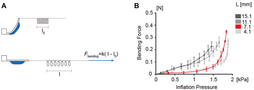
FIGURE 6. Experimental setup for bending force measurement. (A) Illustration of force measurement method using a rubber band. The rubber band is described as a spring in the figure. The rubber band was pulled to estimate the bending force until the flexible body became parallel with the pulling direction. (B) Bending force curves as a function of inflation pressure. 4.1, 7.1, 11.1 and 15.1 mm chamber lengths were tested.
In this study, we used a comprehensive theoretical analyses and experiments to describe the behavior of bending type balloon actuator and studied the effect of mechanical properties of the material and geometrical parameters of the actuator on its performance. Specifically, we found that increasing the length of the chamber amplified the bending angle and an increase in membrane thickness caused smaller bending angles, which were explained by an exponential growth model. Our analyses showed a key influence of the mechanical properties of the materials and its differences on the degree and direction of the bending angle of the actuator. Furthermore, employing a simple, customized setup, we have determined the force applied by the actuators during their function. In this proof-of-concept study, we used chamber length as a parameter to estimate the forces. Similarly, other design parameters can be varied to study their effect on the force which needs to be verified in future studies. While the analytical model described here utilizes an exponential growth model, it only validates functional actuators and does not account for the upper limit or failure of actuation. Nonetheless, the analytical model described in this study could serve as an important tool in designing soft robotics with controlled and versatile bending movements. Additionally, rather than identifying a universally optimum actuator, our approach allows selection of application-specific design to achieve targeted function (for example, higher bending angle, lower response times, directional bending etc). While actuators with only a single chamber have been analyzed in the current study, the framework described here can be extended to study actuators with multiple chambers in series or parallel as used in several soft robots (Shepherd et al., 2011; Maruthavanan et al., 2021). Such theoretical and predictive analysis can help reduce experimental time and resources associated with selecting optimal soft actuators for targeted functions such as designing a gripper with individual “fingers” requiring different extent of actuations.
The raw data supporting the conclusions of this article will be made available by the authors, without undue reservation.
UK and VK contributed equally to the study. UK, VK, and SV conceived the study. UK, VK, and BR performed the experiments and analyses. All authors contributed to the writing of the manuscript.
Part of this work was performed at the Duke University Shared Materials Instrumentation Facility (SMIF), a member of the North Carolina Research Triangle Nanotechnology Network (RTNN), which is supported by the National Science Foundation (award number ECCS-2025064) as part of the National Nanotechnology Coordinated Infrastructure (NNCI).
The authors declare that the research was conducted in the absence of any commercial or financial relationships that could be construed as a potential conflict of interest.
All claims expressed in this article are solely those of the authors and do not necessarily represent those of their affiliated organizations, or those of the publisher, the editors and the reviewers. Any product that may be evaluated in this article, or claim that may be made by its manufacturer, is not guaranteed or endorsed by the publisher.
The Supplementary Material for this article can be found online at: https://www.frontiersin.org/articles/10.3389/frobt.2022.991748/full#supplementary-material
Balak, R., and Mazumdar, Y. C. (2020). “Multi-modal pneumatic actuator for twisting, extension, and bending,” in 2020 IEEE/RSJ International Conference on Intelligent Robots and Systems (IROS), Las Vegas, NV (IEEE), 8673–8679.
Cianchetti, M., Laschi, C., Menciassi, A., and Dario, P. (2018). Biomedical applications of soft robotics. Nat. Rev. Mater. 3 (6), 143–153. doi:10.1038/s41578-018-0022-y
Dämmer, G., Lackner, M., Laicher, S., Neumann, R., and Major, Z. (2021). Design of an inkjet-printed rotary bellows actuator and simulation of its time-dependent deformation behavior. Front. Robot. AI 8, 663158. doi:10.3389/frobt.2021.663158
Dang, Y., Stommel, M., Cheng, L. K., and Xu, W. (2019). A soft ring-shaped actuator for radial contracting deformation: Design and modeling. Soft Robot. 6 (4), 444–454. doi:10.1089/soro.2018.0064
El-Atab, N., Mishra, R. B., Al-Modaf, F., Joharji, L., Alsharif, A. A., Alamoudi, H., et al. (2020). Soft actuators for soft robotic applications: A review. Adv. Intell. Syst. 2 (10), 2000128. doi:10.1002/aisy.202000128
Fujiwara, N., Sawano, S., and Konishi, S. (2009). “Linear expansion and contraction of paired pneumatic baloon bending actuators toward telescopic motion,” in 2009 IEEE 22nd International Conference on Micro Electro Mechanical Systems, Sorrento, Italy (IEEE), 435–438.
Gorissen, B., De Volder, M., De Greef, A., and Reynaerts, D. (2011). Theoretical and experimental analysis of pneumatic balloon microactuators. Sensors Actuators A: Phys. 168 (1), 58–65. doi:10.1016/j.sna.2011.03.057
Gorissen, B., De Volder, M., and Reynaerts, D. (2018). Chip-on-tip endoscope incorporating a soft robotic pneumatic bending microactuator. Biomed. Microdevices 20 (3), 73. doi:10.1007/s10544-018-0317-1
Gorissen, B., Reynaerts, D., Konishi, S., Yoshida, K., Kim, J. W., and De Volder, M. (2017). Elastic inflatable Actuators for soft robotic applications. Adv. Mater. 29 (43), 1604977. doi:10.1002/adma.201604977
Hashem, R., Stommel, M., Cheng, L. K., and Xu, W. (2021). Design and characterization of a bellows-driven soft pneumatic actuator. Ieee. ASME. Trans. Mechatron. 26 (5), 2327–2338. doi:10.1109/tmech.2020.3037643
Hu, W., and Alici, G. (2020). Bioinspired three-dimensional-printed helical soft pneumatic actuators and their characterization. Soft Robot. 7 (3), 267–282. doi:10.1089/soro.2019.0015
Jeong, O. C., Kusuda, S., and Konishi, S. (2005). “All PDMS pneumatic balloon actuators for bidirectional motion of micro finger,” in 18th IEEE International Conference on Micro Electro Mechanical Systems, 2005 MEMS 2005, 407–410.
Jin, T., Sun, Z., Li, L., Zhang, Q., Zhu, M., Zhang, Z., et al. (2020). Triboelectric nanogenerator sensors for soft robotics aiming at digital twin applications. Nat. Commun. 11 (1), 5381. doi:10.1038/s41467-020-19059-3
Kim, Y., and Cha, Y. (2020). Soft pneumatic gripper with a tendon-driven soft origami pump. Front. Bioeng. Biotechnol. 8, 461. doi:10.3389/fbioe.2020.00461
Konishi, S., Nokata, M., Jeong, O. C., Kusuda, S., Sakakibara, T., Kuwayama, M., et al. (2006). “Pneumatic micro hand and miniaturized parallel link robot for micro manipulation robot system,” in Proceedings 2006 IEEE International Conference on Robotics and Automation, 2006 ICRA 2006, Orlando, FL (IEEE), 1036–1041.
Kumar, V., Ko, U. H., Zhou, Y., Hoque, J., Arya, G., and Varghese, S. (2021). Microengineered materials with self-healing features for soft robotics. Adv. Intell. Syst. 3 (7), 2100005. doi:10.1002/aisy.202100005
Lu, Y., and Kim, C. J. (2003). “Micro-finger articulation by pneumatic parylene balloons,” in TRANSDUCERS ’03 12th International Conference on solid-State Sensors, Actuators and Microsystems Digest of Technical Papers (Cat No03TH8664), Boston, MA (IEEE), 276–291.
Marchese, A. D., Katzschmann, R. K., and Rus, D. (2015). A recipe for soft fluidic elastomer robots. Soft Robot. 2 (1), 7–25. doi:10.1089/soro.2014.0022
Maruthavanan, D., Seibel, A., and Schlattmann, J. (2021). Fluid-structure interaction modelling of a soft pneumatic actuator. Actuators 10 (7), 163. doi:10.3390/act10070163
Pagoli, A., Chapelle, F., Corrales-Ramon, J. A., Mezouar, Y., and Lapusta, Y. (2021). Review of soft fluidic actuators: Classification and materials modeling analysis. Smart Mater. Struct. 31 (1), 013001. doi:10.1088/1361-665x/ac383a
Park, Y. L., Majidi, C., Kramer, R., Bérard, P., and Wood, R. J. (2010). Hyperelastic pressure sensing with a liquid-embedded elastomer. J. Micromech. Microeng. 20 (12), 125029. doi:10.1088/0960-1317/20/12/125029
Polygerinos, P., Wang, Z., Overvelde, J. T. B., Galloway, K. C., Wood, R. J., Bertoldi, K., et al. (2015). Modeling of soft fiber-reinforced bending actuators. IEEE Trans. Robot. 31 (3), 778–789. doi:10.1109/tro.2015.2428504
Ranzani, T., Russo, S., Bartlett, N. W., Wehner, M., and Wood, R. J. (2018). Increasing the dimensionality of soft microstructures through injection-induced self-folding. Adv. Mater. 30 (38), 1802739. doi:10.1002/adma.201802739
Schaffner, M., Faber, J. A., Pianegonda, L., Rühs, P. A., Coulter, F., and Studart, A. R. (2018). 3D printing of robotic soft actuators with programmable bioinspired architectures. Nat. Commun. 9 (1), 878. doi:10.1038/s41467-018-03216-w
Schmitt, F., Piccin, O., Barbé, L., and Bayle, B. (2018). Soft robots manufacturing: A review. Front. Robotics AI 5, 84. doi:10.3389/frobt.2018.00084
Schreiber, F., and Manns, M. (2021). Long-term cycle-tests of an additively manufactured soft ring-gripper. Procedia CIRP 104, 798–802. doi:10.1016/j.procir.2021.11.134
Shepherd, R. F., Ilievski, F., Choi, W., Morin, S. A., Stokes, A. A., Mazzeo, A. D., et al. (2011). Multigait soft robot. Proc. Natl. Acad. Sci. U. S. A. 108 (51), 20400–20403. doi:10.1073/pnas.1116564108
Shintake, J., Cacucciolo, V., Floreano, D., and Shea, H. (2018). Soft robotic grippers. Adv. Mater. 30 (29), 1707035. doi:10.1002/adma.201707035
Shintake, J., Sonar, H., Piskarev, E., Paik, J., and Floreano, D. (2017). “Soft pneumatic gelatin actuator for edible robotics,” in 2017 IEEE/RSJ International Conference on Intelligent Robots and Systems (IROS), Vancouver, BC (IEEE), 6221–6226.
Surakusumah, R. F., Mohd, F. A., Dewi, D. E. O., and Supriyanto, E. (2014). “Development of a half sphere bending soft actuator for flexible bronchoscope movement,” in 2014 IEEE International Symposium on Robotics and Manufacturing Automation (ROMA), 120–125.
Verrelst, B., Ham, R. V., Vanderborght, B., Daerden, F., Lefeber, D., and Vermeulen, J. (2005). The pneumatic biped ?Lucy? actuated with pleated pneumatic artificial muscles. Auton. Robots 18 (2), 201–213. doi:10.1007/s10514-005-0726-x
Wang, Z., Volinsky, A. A., and Gallant, N. D. (2014). Crosslinking effect on polydimethylsiloxane elastic modulus measured by custom-built compression instrument. J. Appl. Polym. Sci. 131, 41050. doi:10.1002/app.41050
Wehner, M., Truby, R. L., Fitzgerald, D. J., Mosadegh, B., Whitesides, G. M., Lewis, J. A., et al. (2016). An integrated design and fabrication strategy for entirely soft, autonomous robots. Nature 536 (7617), 451–455. doi:10.1038/nature19100
Whitesides, G. M. (2018). Soft robotics. Angew. Chem. Int. Ed. 57 (16), 4258–4273. doi:10.1002/anie.201800907
Xavier, M. S., Fleming, A. J., and Yong, Y. K. (2021). Finite element modeling of soft fluidic actuators: Overview and recent developments. Adv. Intell. Syst. 3 (2), 2000187. doi:10.1002/aisy.202000187
Xavier, M. S., Tawk, C. D., Zolfagharian, A., Pinskier, J., Howard, D., Young, T., et al. (2022). Soft pneumatic actuators: A review of design, fabrication, modeling, sensing, control and applications. IEEE Access 10, 59442–59485. doi:10.1109/access.2022.3179589
Yan, J., Zhang, X., Xu, B., and Zhao, J. (2018). A New spiral-type inflatable pure torsional soft actuator. Soft Robot. 5 (5), 527–540. doi:10.1089/soro.2017.0040
Zaidi, S., Maselli, M., Laschi, C., and Cianchetti, M. (2021). Actuation Technologies for soft robot grippers and manipulators: A review. Curr. Robot. Rep. 2 (3), 355–369. doi:10.1007/s43154-021-00054-5
Keywords: soft actuators, pressurized actuators, balloon actuators, bending actuator, balloon actuator
Citation: Ko UH, Kumar V, Rosen B and Varghese S (2022) Characterization of bending balloon actuators. Front. Robot. AI 9:991748. doi: 10.3389/frobt.2022.991748
Received: 11 July 2022; Accepted: 25 August 2022;
Published: 19 September 2022.
Edited by:
Samuel Rosset, University of Auckland, New ZealandReviewed by:
Matheus S. Xavier, The University of Newcastle, AustraliaCopyright © 2022 Ko, Kumar, Rosen and Varghese. This is an open-access article distributed under the terms of the Creative Commons Attribution License (CC BY). The use, distribution or reproduction in other forums is permitted, provided the original author(s) and the copyright owner(s) are credited and that the original publication in this journal is cited, in accordance with accepted academic practice. No use, distribution or reproduction is permitted which does not comply with these terms.
*Correspondence: Shyni Varghese, c2h5bmkudmFyZ2hlc2VAZHVrZS5lZHU=
†These authors have contributed equally to this work
Disclaimer: All claims expressed in this article are solely those of the authors and do not necessarily represent those of their affiliated organizations, or those of the publisher, the editors and the reviewers. Any product that may be evaluated in this article or claim that may be made by its manufacturer is not guaranteed or endorsed by the publisher.
Research integrity at Frontiers
Learn more about the work of our research integrity team to safeguard the quality of each article we publish.