 Will Barnett
 Ana Cavalcanti
 Alvaro Miyazawa
95% of researchers rate our articles as excellent or good
Learn more about the work of our research integrity team to safeguard the quality of each article we publish.
Find out more
ORIGINAL RESEARCH article
Front. Robot. AI , 28 October 2022
Sec. Field Robotics
Volume 9 - 2022 | https://doi.org/10.3389/frobt.2022.991637
This article is part of the Research Topic Standardized Software Frameworks for Robotics in Nuclear Applications View all articles
The need for robotic systems to be verified grows as robots are increasingly used in complex applications with safety implications. Model-driven engineering and domain-specific languages (DSLs) have proven useful in the development of complex systems. RoboChart is a DSL for modelling robot software controllers using state machines and a simple component model. It is distinctive in that it has a formal semantics and support for automated verification. Our work enriches RoboChart with support for modelling architectures and architectural patterns used in the robotics domain. Support is in the shape of an additional DSL, RoboArch, whose primitive concepts encapsulate the notion of a layered architecture and architectural patterns for use in the design of the layers that are only informally described in the literature. A RoboArch model can be used to generate automatically a sketch of a RoboChart model, and the rules for automatic generation define a semantics for RoboArch. Additional patterns can be formalised by extending RoboArch. In this paper, we present RoboArch, and give a perspective of how it can be used in conjunction with CorteX, a software framework developed for the nuclear industry.
Robotic systems are being used in an increasingly diverse range of applications, and in more dynamic and unstructured environments. With autonomy and the ability to operate in close proximity to humans, safety becomes an issue. Furthermore, robotic systems and their software are becoming more complex. In previous work, we have contributed to the verification of robotic systems using a domain-specific language with a formal semantics, namely, RoboChart (Miyazawa et al., 2017, 2019).
In this paper, we present an approach to defining RoboChart models for software that use architectures of wide interest in robotics. It is based on a novel domain-specific notation, RoboArch, presented here for the first time. It embeds robotics software architectural concepts and enables automatic generation, via model transformation, of partial RoboChart models, that is, sketches of RoboChart models that can be completed by designers with application-specific descriptions (of actions and state machines).
The definition of a system’s architecture during its design has been considered a beneficial technique as the scale of software systems has grown. The architecture provides a structural representation that enables the evaluation of system attributes and of alternative system designs and modifications (Bass et al., 2012). From experience, practitioners have identified structures and relationships within system architectures that solve recurring problems. These solutions have been generalised as architectural patterns that are reusable in the design of new systems (Gamma et al., 1995). For the robotics domain, some common patterns have emerged: notably, the use of layers for robot control (Siciliano and Khatib, 2016, pp. 286–289).
In many other complex multidisciplinary domains, Model-Driven Engineering (MDE) is being used successfully to mitigate complexity (Franz et al., 2018). The core principle of MDE is to use abstract models of a system as the primary artefact(s) of its development process. This promotes identification of the underlying concepts free from specific implementation dependencies. The use of abstract models also facilitates the automation of the software development process. In this way developers can devote their time to understanding and solving the domain-specific problems.
Domain-specific languages (DSL) facilitate the development of models by embedding core concepts of a target domain, and enabling the definition of concise representations understood by practitioners. This avoids the need for each development team to identify these concepts, resulting in duplication of work and hindering reusability. Over the last 25 years, there have been considerable developments in MDE for robotics, with the creation of many DSL for its different sub-domains (Nordmann et al., 2016).
Some examples of DSL for robotics include: RobotML (Dhouib et al., 2012), SmartSoft (Stamper et al., 2016), and BCM (Bruyninckx et al., 2013). These DSLs, like the majority available, do not have formally defined semantics (Cavalcanti et al., 2021b). Therefore, the support for formal verification of robotic systems is limited. A recent literature survey (Luckcuck et al., 2019) found sixty-three examples of the application of formal methods within the robotics domain. Formal methods enable the early verification (proof, simulation, and testing) of a system through the use of rigorous automated techniques with mathematical foundations. Early use of verification techniques and high levels of automation enable the development of systems that are more reliable and cheaper.
RoboChart is a DSL for modelling robotics software controllers using state machines and a simple component model; RoboChart makes innovative use of formal methods for automated verification. The associated tool, RoboTool1, provides features of MDE, which include a graphical interface for creating models, and automatic generation of source code and mathematical descriptions. Additionally, RoboChart supports automatic verification of properties such as deadlock and livelock freedom using model checking, along with semi-automatic verification techniques using theorem proving (Cavalcanti A. L. C. et al., 2021).
To date, RoboChart has been used to model more than twenty proof-of-concept case studies. They have facilitated the development and demonstration of RoboChart and its verification technology. None of them, however, adopt an elaborate software architecture. For larger robotic systems, support for modelling taking advantage of commonly used architectural patterns can enable explicit modelling of the structure of systems with potential to assist in reuse and compositional design and reasoning.
RoboArch allows the description of layered designs for robotic control software, and of design patterns for each layer. In this paper, we not only give an overview of RoboArch via a motivating example, but also present its complete metamodel and set of well-formedness conditions that specify the valid RoboArch models. We also describe our model-transformation approach, based on 50 rules, mechanised to generate automatically a sketch of a RoboChart model from a RoboArch architectural design of a system.
Besides supporting the description of architectural designs, RoboArch formalises a notion of a layered architecture and other patterns. Most of these patterns are described in the literature only informally, sometimes with different variations described by different authors. At best, patterns are realised in an implementation or programming language. Such descriptions necessarily mix the core concepts of the architectural patterns with those of the application or programming language. In contrast, the RoboArch formalisation identifies the core concepts of a pattern and their relationship.
The CorteX framework (Caliskanelli et al., 2021) has been designed for use in nuclear robotics to address the challenges of developing their complex robotic systems that need to be maintained over long periods of time, often to deal with changing requirements due to the unknown operational conditions. CorteX favours the development of maintainable and extensible systems through specialised data and communications designs. Designs for the CorteX middleware are inherently concurrent.
Our vision is the alliance of RoboArch and CorteX to support 1) the identification and formalisation of the architectural designs that rely on CorteX and 2) the elicitation of assurance evidence to increase confidence in CorteX-based software and support the construction of assurance arguments. By integrating CorteX with RoboArch, and, via RoboArch, to RoboChart, we connect CorteX to the RoboStar approach to Software Engineering for Robotics (Cavalcanti A. L. C. et al., 2021). With that, we enable, automatic generation of mathematical models that specify the meaning of the RoboArch designs, and automatic and semi-automatic verification of properties via model-checking and theorem proving. Further specialisation of the approach can lead to automatic generation of CorteX code for simulation and deployment.
Our novel contributions in this paper are as follows.
1) Design of RoboArch for description of layered architectures for robotic control software.
2) Definition of the metamodel and well-formedness conditions of RoboArch.
3) Description of a technique for model-to-model transformation from RoboArch to RoboChart.
4) Formalisation of the reactive-skills architectural pattern for design of control layers, illustrating a general approach to formalise patterns using RoboArch and RoboChart.
5) Discussion of perspectives for allying the use of RoboArch and CorteX, and, in particular, of the formalisation of CorteX in RoboArch and RoboChart.
These results enable use of MDE in the development of control software for robotic systems in a way that focusses on use of well-known patterns allied with the advantages of modern verification techniques. RoboChart, and, therefore, RoboArch, are part of a design and verification framework, called RoboStar, that supports automated generation of simulations, tests, and proof.
In the next section, we describe related work on architectures for robotics. Section 3 presents RoboArch: metamodel, well-formedness conditions, and translation to RoboChart. Section 4 shows how a design pattern can be formalised in RoboArch using the example of reactive skills. In Section 5 we conclude, discussing our approach for the integration of RoboArch and CorteX as future work.
In this section, we discuss the literature on architectural patterns for robotics. Crucially, this justifies our choice of layer as a core concept in RoboArch, but also indicates other patterns of interest, including reactive skills, which we also formalise in this paper.
RoboArch is not related to the homonym in (Bonato and Marques, 2009), which is a tool to support the development of mobile robots. The focus in (Bonato and Marques, 2009) is on implementation, not modelling, of hardware-software co-designs based on hardware and software components, and code generation for FPGA, not software architectures. Moreover, there is no semantics or support for verification beyond simulation for the notation adopted by RoboArch to define the compositions.
Other works that share our aim to reduce effort in the development of control software in robotics focus on the programming, rather than the modelling, level. The result is a variety of middleware, encouraging code reuse and component-based development (Bruyninckx, 2001; Metta et al., 2006; Ando et al., 2008; Chitta et al., 2017; Muratore et al., 2017). These works provide useful resources for programming, but do not address the issues arising from a code, rather than model-based, approach to development. Work on RoboArch and RoboChart is complementary. In particular, we consider here how we can provide direct support for use of the modern CorteX middleware that has a track record in the nuclear industry.
Historical architectural patterns include Sense Plan Act (SPA) (Siciliano and Khatib, 2016, p. 285) and subsumption (Brooks, 1986). SPA is an example of a pattern that is deliberative: time is taken to plan what to do next, and then the plan is acted out with no sensing or feedback during acting. A robot using SPA in a dynamically changing world can be slow and error prone in response to environmental change.
Conversely, subsumption is an example of an architectural pattern that is reactive, where the environment is constantly sensed and used to directly shape the robot’s actions. A robot using subsumption responds rapidly to a changing world; however, complex actions are difficult to achieve.
More recent hybrid architectural patterns combine the principles from SPA and subsumption to benefit from both the deliberative and reactive properties. In total, twenty-two architectural patterns used by robotics systems have been identified from the literature; these are listed in Table 1. Five have been selected for discussion based upon evidence of application, reuse, and activity of development. The collective publications that focus on an architectural pattern have been used to find evidence of application, with the scale of any documented application used to give preference to patterns that have been used in large deployments in the real world. The number of publications where an architectural pattern was used in a new application has been used to asses reuse. Finally, preference has been given to patterns with recent activity, determined by the date and frequency of publications where the pattern has been used.
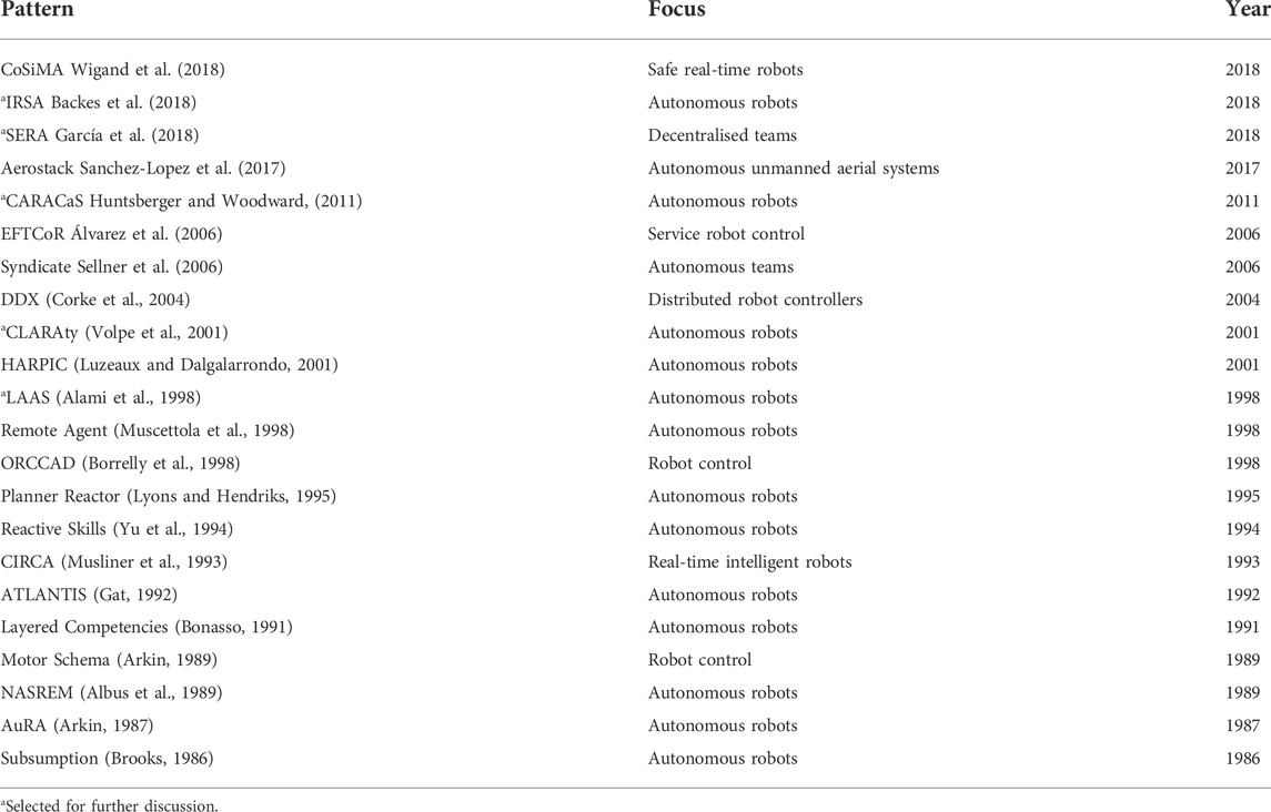
TABLE 1. The patterns identified from the literature.
LAAS was developed at LAAS2 in 1998 for autonomous robots. A fundamental goal of LAAS is to provide both deliberative and reactive capabilities required for autonomy.
The LAAS pattern is made up of the following three layers. The Functional Layer provides basic robot actions that are organised into modules consisting of processing functions, task loops, and monitoring functions for reactive behaviour. An Execution Control Layer selects functions from the functional layer to carry out sequences of actions determined by the decision layer. Finally, the Decision Layer plans the sequence of actions necessary to achieve mission goals and supervises the execution of the plans.
The functional layer consists of a network of modules that provide services related to a particular sensor, actuator, or data resource of the robot. All modules have a fixed generic structure made up of a controller and execution engine. A tool can be used to generate module source code. The services provided by the modules are accessed by the executive layer above and other modules from the functional layer through the use of a non-blocking client-server communication model.
The execution control layer bridges the slow, high-level, processing of the decision layer, and the fast, low-level, control of the functional layer. It has an executive module that takes sequences of actions from the decision layer, and selects and triggers the functions that the functional layer must carry out. In addition, the executive receives replies from the functional layer and reports activity progress to the decision layer.
The decision layer has one or more pairs of a supervisor and a planner. The supervisor takes a sequence of actions from the planner and manages their execution by communicating them to the execution layer, and responding to reports received from it. The planner creates a sequence of actions to achieve a goal. The supervisor also passes down situations to monitor and associated responses within the constraints of the plan. These responses enable the lower layers to react without the need for involvement of the decision layer, improving response time and reducing unnecessary replanning.
LAAS has been used in the implementation of the ADAM rough terrain planetary exploration rover (Chatila et al., 1995), and of three Hilare autonomous environment exploration robots as part of the MARTHA European project. More recently, Behaviour Interaction Priority (BIP) models have been used to verify the functional layer of the LAAS pattern (Silva et al., 2015).
CLARAty (Coupled Layer Architecture for Robotic Autonomy) was developed at NASA in 2001 for planetary surface-exploration rovers. CLARAty is designed to be reusable and to support multiple robot platforms; it consists of two-layers: a functional layer, and a decision layer formed by combining the planning and executive layers from a three-layer architecture. A key concept defined in CLARAty is granularity, which reflects the varying levels of deliberativeness available to the robotic system.
The functional layer provides a software interface to the hardware capabilities of the robot, and it is structured using an object-oriented hierarchy. At the top of the hierarchy is the Robot superclass from which everything inherits. At subsequent levels down the hierarchy, classes are less abstract and each provide functionality for a piece of the robot’s hardware. At the bottom of the hierarchy, each class provides access to a specific piece of hardware functionality and its current state.
Classes can provide functionality that requires minimal input from the decision layer, therefore, this type of class can be considered more reactive. For example, the class for a rover may offer a method for obstacle avoidance. Alternatively classes can provide functionality that requires regular input from the decision layer, therefore, the class can be considered more deliberative. For example, the class for a robotic arm may offer a method for setting the position for one of its five motors.
The single decision layer enables state information between planner and executive to be shared, which means that the planner becomes tightly integrated with the executive. Consequently, discrepancy between the planner and the functional layer’s state is minimised.
The CLARAty pattern has been used for a variety of robot platforms: Rocky 8, FIDO, ROCKY 7, K9 Rovers, and ATRV Jr COTS platform (Nesnas et al., 2006). The different platforms have a variety of deployment architectures, from a single processor requiring hard real-time scheduling, to distributed microprocessors using soft real-time scheduling.
CARACaS (Control Architecture for Robotic Agent Command and Sensing) is an architectural pattern developed at NASA in 2011 for control of autonomous underwater vehicles (AUV), and autonomous surface vehicles (ASV). CARACaS-based software supports operation in uncontrolled environments ensuring the vehicles obey maritime regulations. A CARACaS design supports cooperation between different vehicles and makes use of dynamic planning to adapt to the current environmental conditions and mission goals.
The five main elements of CARACaS are as follows. Actuators interface the actuators of the vehicle. A Behaviour Engine coordinates and enables the composition of behaviours acting on the actuators. The arbitration mechanisms controlling the enabling and disabling of behaviours are subsumption, voting, and interval programming. A Perception Engine creates maps for safe navigation and hazard perception from the sensors. A Dynamic Planning Engine chooses activities to accomplish mission goals while observing resource constraints. For that, it uses Continuous Activity Scheduling Planning Execution and Replanning (CASPER) (Chien et al., 2000), and issues commands to the Behaviour Engine. Finally, a World Model contains state information including plans, maps, and other agents.
Layers are not defined in Huntsberger and Woodward (2011), but a CARACaS design can be partitioned into two layers. At the lowest level, a behavioural layer includes the Actuators, and the Behaviour and Perception Engine elements. The higher layer consists of the Dynamic Planning and the World Model.
Although CARACaS is targeted at autonomous water-based vehicles, it contains all of the required elements to be applied more generally as a pattern for the control of robots.
IRSA (Intelligent Robotics System Architecture) was developed at NASA in 2018 to streamline the transition of robotic algorithms from development onto flight systems by improving compatibility with existing flight software architectures. IRSA uses concepts from other patterns: CARACaS and CLARAty.
The main elements of IRSA are as follows. A Primitive provides low-level behaviours that can have control loops. Behaviour provides autonomy, transitioning between multiple states during execution. The Executive receives and executes a sequence of instruction commands from the planner. The Planner uses the system state from the world model to produce the sequence of command instructions. A Sequence contains the instructions that the robot must perform. A Verifier verifies whether the sequence is valid. Finally, the Robot World Model maintains a model of the robot with local and global state information.
An IRSA design can be mapped onto a three-layer pattern with a common world model accessible to all layers. The behavior and the primitive elements provide control over the robot; so, these two elements can be placed in the bottom layer. The executive receives sequences of commands and manages their execution using the behaviours. Therefore, the executive is the middle layer. The planner uses the state of the system from the world model to create a sequence of commands checked by the verifier. Therefore, the planner, sequence, and verifier elements are in the layer above the executive.
The IRSA architectural pattern has been deployed on a variety of test beds: comet surface sample return, Europa lander, Mars 2020 Controls and Autonomy, and the RoboSimian DARPA challenge.
SERA (The Self-adaptive dEcentralised Robotic Architecture) has been developed at the Chalmers University of Technology in 2018. SERA’s primary goal is to support decentralised self-adaptive collaboration between robots or humans, and it is based on the three-layer self-management architectural pattern. SERA has been evaluated in collaboration with industrial partners in the Co4Robots H2020 EU project.
The layers of the SERA pattern are as follows. The Component Control Layer provides software interfaces to the robot’s sensors and actuators, grouped into control action components responsible for particular areas of functionality. The Change Management Layer receives the local mission and creates a plan in order satisfy its goals. It executes the plan by calling appropriate control actions from the component control layer. Finally, the Mission Management Layer manages the local mission for each robot and communicates with other robots in order to synchronise and achieve the global mission.
The mission management layer receives a mission specification from a central station as a temporal logic formulae. The mission manager checks its feasibility and, if it is feasible, passes the mission to the adaptation manager in the layer below. If the mission is infeasible, a communication and collaboration manager communicates and synchronises with the other robots involved in the mission. During the synchronisation, an updated achievable mission that meets the original mission specification is computed.
This pattern places more functionality in the lowest component control layer. A key feature of SERA is communication among robots, which provides greater flexibility in achieving the mission goals.
Generally no particular pattern or selection of patterns are widely used. There is a tendency for each project to establish its own pattern. Between research groups, however, there is some reuse of patterns.
Layers are a common theme among many of the recent architectural patterns. Even when layers have not been explicitly specified, the elements of a pattern are structured such that they can be mapped onto a layered architectural pattern. All patterns have a functional layer that interacts with the robots sensors and actuators. The upper layers following the functional layer vary in number and purpose.
The functional layer is required by all architectural patterns because every robot requires a means to sense and interact with its environment. From the patterns surveyed, this layer can be categorised as either service or behavioural. CLARAty, LAAS and SERA are all examples of patterns that have a service-based functional layer, whereas, CARACaS and IRSA have behavioural-based functional layers.
Examples of behavioural control patterns that can be used for functional layer include subsumption (Brooks, 1986) and reactive skills as used by the control layer of 3T (Bonasso et al., 1997). It is common for the decision layer to be placed directly above the functional layer.
Patterns that do not use an executive layer take different approaches to managing the system’s state. For instance, SERA and CLARAty use information in the decision layer to hold system state. Whereas, CARACaS uses a world model layer that is accessible by all other layers to hold system state.
Some patterns such as SERA have an additional social layer for collaboration between teams of robots. Similarly LAAS supports this through adding supervisor-planner pairs, but considers this to be an extension of the decision layer rather than a new layer. Generally the layered pattern lends itself to the addition of new layers for extending the level of system capability.
RoboArch directly supports the definition of layered architectures, with an arbitrary number of layers. A degenerate layered architecture with just one layer can be used to define a design that does not actually uses layers. As indicated above, however, the use of more elaborate layers, some using specific patterns themselves, is common. In what follows, we present the RoboArch notation.
In this section, we show how a layered design can be described using RoboArch. We give an overview using the example of an office delivery robot from (Siciliano and Khatib, 2016, pp. 291–295) (Section 3.1). In Section 3.2 we present the complete metamodel and well-formedness conditions of RoboArch. Finally, in Section 3.3, we describe the RoboChart model defined by a RoboArch design. In the next Section 4, we show an example of how a pattern for the control layer can be characterised and used.
RoboArch is a self-contained notation that can be used independently. As mentioned, however, its semantics is given by translation rules that define a (sketch of a) RoboChart model. This not only gives RoboArch a precise and formal semantics, but also paves the way for the use of the RoboStar framework to design and verify the control software. Figure 1 gives an overview of the possibilities.
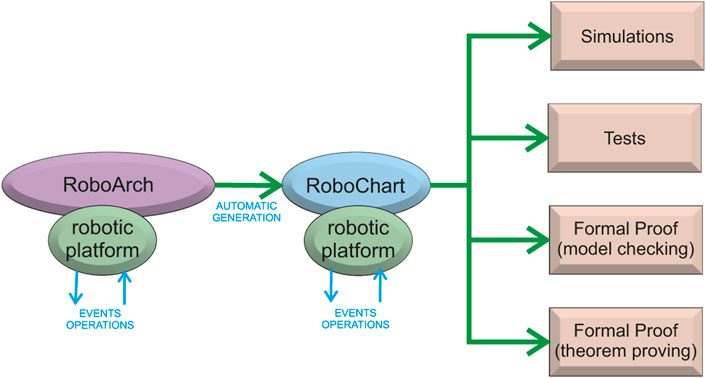
FIGURE 1. RoboArch in the context of RoboStar. With a RoboArch architectural design, we can generate automatically a sketch of a RoboChart behavioural model. Using the RoboChart model, we can take advantage of a plethora of modern verification techniques supported by automated generation of artefacts.
As indicated in Figure 1, a key concept in RoboArch is that of a robotic platform. RoboArch designs are platform independent, so the robotic platform here describes the services the robot provides that can be used in the development of the control software. The services are abstractions of the robot’s sensors and actuators defined via the declaration of input and output events and operations that can be realised via actual sensors and actuators. The same approach is taken in RoboChart.
To give an overview of the RoboArch notation, we consider the example of a robot whose goal is to deliver items of post within a typical office building, transporting them from a central mailroom to each of the offices within the building. To achieve its goal the robot must safely navigate along the corridors of the building while avoiding any obstacles such as people and furniture.
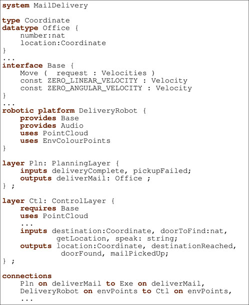
Listing 1. A system and its type declarations.
A RoboArch model for the mail delivery system is sketched in Listing 1. A system clause gives a name to a model and introduces the outer scope to define the layers and the robotic platform. The robotic platform must be used by a single layer, usually the control layer. In addition to the architectural elements, a RoboArch model also contains definitions for types, functions, interfaces, and connections. For our example, Line 1 of Listing 1 declares the system with the name MailDelivery.
RoboArch adopts the type constructors and typing rules of the well-established data modelling notation Z (Woodcock and Davies, 1996), allowing the definition of primitive types, records, sets, and so on. RoboChart and all RoboStar notations adopt the same typing approach. By adopting the Z type system, we benefit from a well-known powerful type system, which has the expected facilities to define a rich, possibly abstract, data model, and that is supported by verification tools. In our example, the next few lines define types. Most type definitions are omitted here, but the complete example is available3.
Robotic platforms are normally defined in terms of interfaces. For our example, the robotic platform is named DeliveryRobot, and its definition references interfaces Base, Audio, PointCloud, and EnvColourPoints, some omitted in Listing 1. Interfaces group events or operations, and are referenced using provides and uses clauses in a platform definition. The Base interface models the interactions that control movement. There is one operation Move and two constants. Move is an abstraction for motor functionality that can be accessed by the software via a call to this operation. It is a service provided by the platform, since Base is declared in a provides clause. The interfaces declared in uses clauses contain events that represent points of interaction (inputs and outputs), corresponding to inputs from sensors, or outputs to actuators. They are used by connecting the platform events to those of a layer.
The design in Listing 1 is a typical three-layer architecture. Every layer has a unique name, and optionally can have a type, a pattern, inputs and outputs. The three specific layer types are ControlLayer, ExecutiveLayer, and PlanningLayer. We can also not provide a type so that a customised architectural structure can be defined. The services of a layer are accessed through its inputs and outputs.
The layer clause is used to define the layer name and type. In Listing 1, we show a layer with name Pln and type PlanningLayer. It has one output deliverMail of type Office that requests the number of the office to which mail is currently being delivered. There are two inputs deliveryComplete and pickupFailed that have no associated value type; their occurrence indicates an outcome of the currently requested delivery. The inputs and outputs are used to communicate with another layer or the robotic platform; in our example communication is with an executive layer, omitted in Listing 1.
A layer of control type can directly communicate with a robotic platform, and so reference platform interfaces. The control layer for our example is Ctl. Its inputs and outputs communicate with the executive layer and DeliveryRobot. The requires and uses clauses reference the interfaces with the operations of the platform that it requires and, the events that it uses. While an ExecutiveLayer and a PlanningLayer cannot require or use services of a platform, a generic layer also can.
The connections among the layers and the robotic platform are defined under a system’s connections clause. Each connection is unidirectional and connects an input or output on a layer or event of the platform to another. Listing 1 shows some of the connections for our mail delivery example. For example, the first declares a connection from the Pln layer’s deliverMail output event to an Exe layer’s deliverMail input event. The second connection is between the robotic platform (DeliveryRobot) and the control layer (Ctl). Several other connections are omitted.
In the next section, we give a complete description of the structure of RoboArch designs.
Figure 2 presents the RoboArch metamodel: the classes, and their attributes and associations, that represent a RoboArch design. The main class is
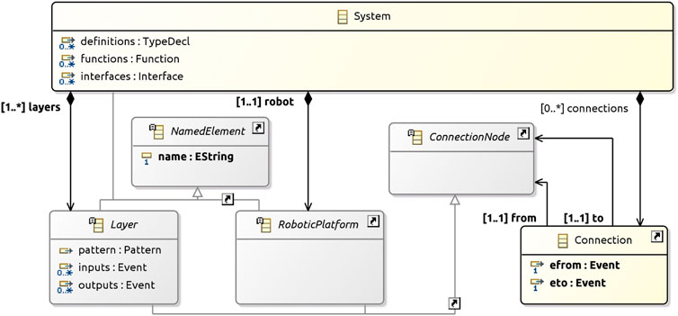
FIGURE 2. System metamodel.
The
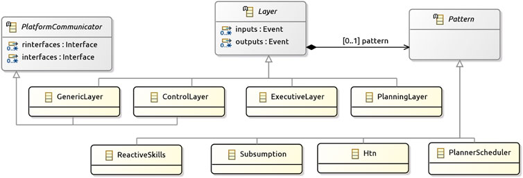
FIGURE 3. Layers metamodel.
As mentioned,
Not all models that can be created obeying the metamodel are valid. For instance, considering just the restrictions defined by the metamodel, we can create an architecture that connects events of different types. No typing rules are captured in the metamodel. As another example, the metamodel allows the specification of an architecture without connections with the robotic platform. Such design is for a software that does not carry out any visible task, and we regard it as invalid. Although we could translate such designs to RoboChart, there is little point in delaying the identification of problems by working with invalid designs.
Instead, we define well-formedness conditions, presented here in Table 2, which characterise the valid designs. These conditions provide modellers with additional guidance and support for validation when defining an architecture.The conditions can be checked by the RoboArch tool.
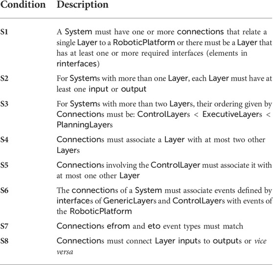
TABLE 2. The well-formedness conditions of RoboArch.
S1 ensures that it is possible to interact with the platform. Because a
In the next section we describe how a RoboArch design can be formalised in RoboChart, and how transformation rules can be used to generate RoboChart models.
Table 3 presents an informal account of how RoboArch elements can be mapped to a RoboChart model. Transformation rules formalise this mapping, defining the (formal) semantics of RoboArch; their implementation allows the automatic generation of RoboChart models. RoboChart’s formal semantics underpins RoboArch and allows properties of a RoboArch design to be verified (see Figure 1). Figure 4 presents parts of the RoboChart model for the design in Listing 1.
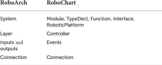
TABLE 3. Mapping RoboArch to RoboChart.
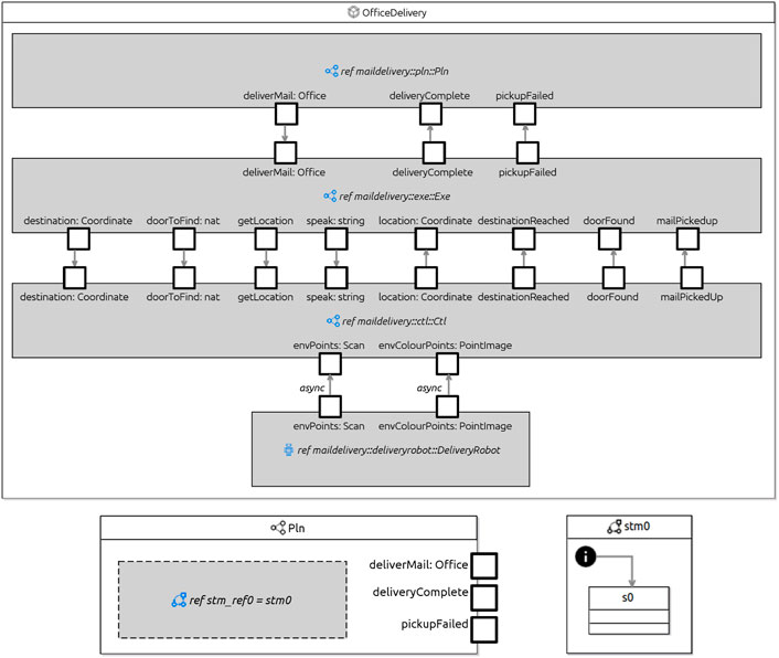
FIGURE 4. Delivery robot in RoboChart.
The top-level transformation rule, shown in Figure 5, maps a RoboArch
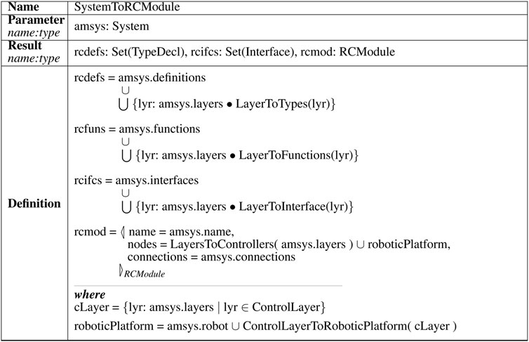
FIGURE 5. Example transformation rule.
A module is the RoboChart element representing a (parallel) robotic control software. In Figure 4, the module
A RoboChart module has its platform-independent behaviour characterised by a
The
Figure 4 shows the RoboChart controller for the planning layer
For illustration, we show the top rule SystemToRCModule in Figure 5; it uses further rules (omitted here) to specify the RoboChart resulting elements rcdefs, rcfuns, rcifs, and rcmod that give the semantics of the system amsys given as input. The other rules are specified in the same style.
The resulting RoboChart type definitions rcdefs are the union of RoboArch system type definitions amsys. definitions and the generalised union (⋃) of the definitions resulting from applying a rule LayerToTypes to each RoboArch layer (amsys.layers). The types used in the rule definitions (TypeDecl, Interface, RCModule, and all others) are part of the RoboArch and RoboChart metamodels. They define the valid attributes (amsys.definitions, amssys layers, and so on). The definitions of the results rcfuns and rcifcs are similar to that of rcdefs, but use the rules LayerToFunctions and LayersToInterfaces.
The resulting RoboChart module rcmod is given by an object (specified by the construct ◁ _ ▷RCModule) whose attributes define the name, nodes (controllers and robotic platform), and connections. The name of the module is the system name amsys. name. The nodes are the controllers defined by applying the rule LayersToControllers to the system’s layers and a roboticPlatform as defined in the where clause. The connections of the module are those defined directly by amsys. connections.
The where clause defines the roboticPlatform to be the union of the RoboArch platform amsys. robot with the result of applying a rule ControlLayerToRoboticPlatform to the control layer cLayer. The platform amsys. robot is directly mapped to the RoboChart model. The layer cLayer is defined (via a set comprehension) as the layer lyr of amssys layers whose type is ControlLayer. The well-formedness conditions ensure that there is at most one such layer. With the use of ControlLayerToRoboticPlatform, we cater for the possibility that a pattern in the control layer extends the definition of the platform.
Although the translation of a layered design from RoboArch to RoboChart is reasonably direct, use of RoboArch, instead of constructing a RoboChart model from the start, has several advantages. RoboArch provides clear guidance on how to define and connect a robotic platform and the controllers; validation ensures definition of proper layers. On the other hand, translation to RoboChart provides support for verification. For example, we can prove that the RoboArch design is deadlock free.
In the next section, we show how we can enrich the definition of a layer.
With the RoboArch framework defined in the previous section, we can now formalise and use specific architectural patterns. In this section, we explain how to achieve that using the reactive-skill pattern for illustration. We first provide an overview of the pattern (Section 4.1), and then formalise it via a metamodel and well-formedness conditions (Section 4.2), and via transformation to RoboChart (Section 4.3).
The reactive-skills pattern can be used in the control layer, typically of a three-layer architecture (Bonasso et al., 1997). It combines deliberation and reactivity to improve robustness. The pattern has been used in a variety of applications: a robot to identify people and approach them (Wong et al., 1995), a trash collecting robot (Firby et al., 1995b), a robot that navigates a building (Firby et al., 1995a), and in the automation of remote-manipulation system procedures for the space shuttle (Bonasso et al., 1998). A framework that allows skills to be implemented using C, C++, Pascal, LISP and REX is available (Yu et al., 1994).
We characterise the reactive skills pattern by two concepts: skills and a skills manager. A skill performs an operation using input values, which can be from sensors or outputs of other skills. The skill’s output values can establish associations to and from the robotic platform, or be the result of applying a computational transform to the skill’s inputs. A set of skills is used together to accomplish a task identified in the dependant (typically executive) layer. A skills manager is a cyclic mechanism that coordinates communication between skills and provides an interface for the dependant layer to: run the skills required for a task, receive notifications from monitored events, and set and get parameter values of skills.
Skills can be of one of two types: D-Skill or C-Skill (Yu et al., 1994). D-Skills interface physical devices such as sensors and actuators with the other skills of the control layer; their input values are actuation commands and their output values are sensor data. C-Skills execute a computational transform using the skill’s inputs to determine its outputs. By the monitoring of skills, the manager triggers events on desired conditions becoming true. Table 4 describes elements used by skills and skills managers.
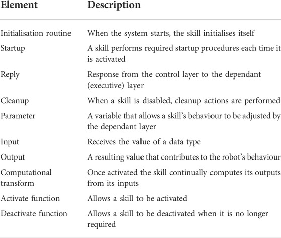
TABLE 4. The elements of reactive skills.
In Listing 2, we sketch the design of the control layer of MailDelivery using reactive skills to specify the behaviours regarding moving the delivery robot to a given target location. The type of pattern specified by the pattern clause determines the subsequent clauses that can be used. For reactive skills, the subsequent clauses are skills, connections, and monitors.
Every skill has a unique name, and optionally parameters, a priority, inputs, and outputs. The skills clause declares the skills. There are separate clauses for defining each type of skill: dskill for D-Skills and cskill for C-Skills. In Listing 2, we show three D-Skills named Move, ColourVision, and Proximity, and one C-Skill DetermineLocation.
RoboArch dskills and cskills declare inputs and outputs using the inputs and outputs clauses. A skill communicating a value to a dskill’s input results in the physical state of the device that the dskill represents being potentially affected. In our example, a value communicated to the Move D-Skill velocity input results in the velocities of the motors in the robot’s base being set.
A value from a dskill’s output represents the state of the environment, as sensed by the device the dskill represents. In our example, a value received from the Proximity skill’s envPoints output determines a range of distances to surfaces in the delivery robot’s field of view.
A C-Skill uses its inputs to compute its outputs resulting in behavior that can be used to accomplish parts of a task. In our example, the DetermineLocation skill takes a colour image of the environment and using an image-based localisation technique calculates the coordinates of the delivery robot. To perform this function, DetermineLocation has one input image of type PointImage, and one output location of type Coordinate. The computational transform that specifies the behaviour of C-Skills can be defined by customising the generated RoboChart model.
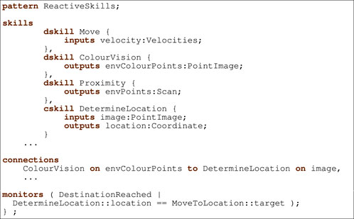
Listing 2. Reactive skills movement.
Skills can communicate with each other via the skills manager. The source and destination of the communication (skills’ inputs and outputs) are determined in a connections clause. Each connection is unidirectional and relates an input of one skill to the output of another. Our example declares a connection from the ColourVision output envColourPoints to the DetermineLocation’s image input.
Layers that depend on a reactive-skills control layer may need to monitor for particular conditions becoming true. To minimise the frequency at which the dependant layer needs to check the conditions, the reactive-skills pattern provides events that are independently triggered to notify the dependant layer of the occurrence of any monitored conditions. The monitors clause declares the monitors for the layer. They have a name and specify the logical condition to be monitored in terms of skill outputs and parameters. For our example, a condition that is monitored is the arrival of the delivery robot at the target location. A monitor DestinationReached has a condition that evaluates to true when the location output of the DetermineLocation skill is equal to the target parameter of a MoveToLocation skill.
Next we describe the RoboArch metamodel and well-formedness conditions for reactive-skills designs.
The class
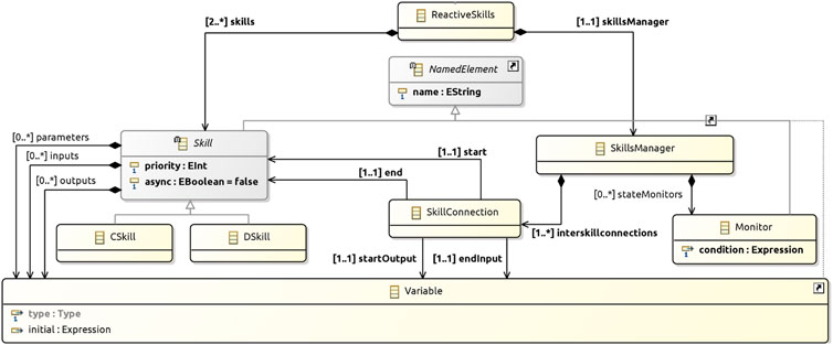
FIGURE 6. Reactive skills metamodel.
In a
The
The well-formedness conditions that apply to reactive-skills designs are presented in Table 5. RS1 and RS2 ensure the use of reactive skills as intended to provide the essential behaviours that use the sensors and actuators (via the services of robotic platform), which other layers depend on to carry out the robot’s tasks. RS3 records that the inputs of the D-Skills correspond to events of the robotic platform. RS4 is needed because a C-Skill or D-Skill in isolation can perform no meaningful function that alters the state of the robot or its environment. A C-Skill requires a D-Skill in order to interact with a sensor or actuator via the services of the robotic platform. With RS5 and RS6, we ensure that every skill contributes to the behaviour of the system. RS7 to RS10 ensure that connections are between inputs and outputs of different skills of the right type. Finally, RS11 ensures that monitors are concerned with skill data.
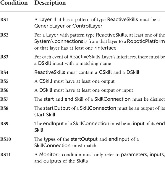
TABLE 5. The well-formedness conditions of reactive-skills designs.
Valid reactive-skill designs, that is, those that satisfy the above well-formedness conditions, can be transformed to (and so formally described as) a RoboChart model, as described in the next section.
Rules that can be used to transform a reactive-skill design to RoboChart are available5. Here we give an overview of our approach formalised by the rules in modelling reactive-skill designs in RoboChart.
A RoboChart controller representing a layer that uses the reactive-skills pattern has one state machine for the skills manager, and one machine for each skill. The skills-manager machine has events to manage the activation and deactivation of skills, receive parameter values, and communicate monitor-event and information replies. A skill machine has events for each of its inputs, outputs, and parameters.
As an example, Figure 7 shows the machine for
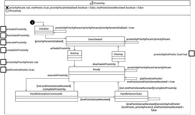
FIGURE 7. RoboChart state machine for Proximity D-Skill.
A D-Skill state machine starts at the state
Typically, the designer needs to enrich the state
In
If an input has been received, the machine moves to
Variations of the D-Skill state-machine definition take into account D-Skills that can output to the platform, and also D-Skills that have several inputs or several outputs.
A machine for a C-skill is shown in Figure 8. It is very similar to that of a D-Skill; the difference is that, instead of states
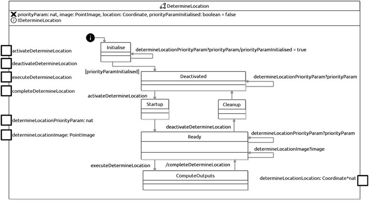
FIGURE 8. RoboChart state machine for DetermineLocation C-Skill.
The designer must complete the definition of this state to reflect the calculations to be carried out by the skill. Once they finish executing, the machine returns to the state
Finally, Figure 9 sketches the machine for the skills manager. The complete machine for our example that can be automatically generated is too large to include here. In the sketch, we show that a skills-manager machine starts in the state
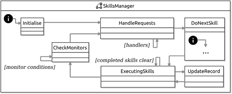
FIGURE 9. RoboChart skills-manager machine for the example.
In the state
The state
The state
In
Using the semantics of RoboChart that is automatically generated, we can prove properties of the design. We have, for example, proved deadlock and livelock freedom, and some other trace-based properties of some of the machines that are automatically generated. In these proofs, we can cater for general properties of any design, and for application-specific properties.
In the next section, we discuss how we can define and formalise a CorteX-based design pattern in RoboArch, opening the same possibilities for CorteX and CorteX designs (see Figure 1).
As already said, CorteX is a framework tailored to the development of complex nuclear robotic systems. It primarily focuses on data representation and communication to solve issues of maintainability and extensibility. In this section, we discuss the integration of CorteX and RoboArch.
We envisage two main approaches for integrating RoboArch and CorteX. The first supports the generation of CorteX implementations of RoboArch models (Section 5.1). The second approach extends RoboArch to support modelling CorteX architectures (Section 5.2).
As discussed in Sections 3, 4, the semantics of RoboArch is specified in terms of RoboChart, which opens the possibility for the generation of several artefacts (see Figure 1). We can obtain automatically mathematical models for verification, such as CSP (Miyazawa et al., 2019) scripts, for verification of reactive and timed properties, and PRISM (Ye et al., 2021) reactive modules, for verification of probabilistic properties. We can also obtain code (Li et al., 2018) and RoboSim models describing simulations (Cavalcanti et al., 2019). RoboSim is a sister notation of RoboChart tailored to the design and verification of simulations with a similar component model and artefact-generation facilities.
A code generator that produces CorteX-compatible implementations of a RoboArch model can take advantage of some of the abovementioned functionalities. The first step requires the generation of the semantics of the RoboArch model in RoboChart as described in this paper. Since CorteX is a cyclic architecture, it is useful to transform (automatically) the resulting RoboChart model into a simulation model, written in RoboSim, via the RoboStar correctness-preserving model-to-model transformation. Next, we can use one of the RoboSim model-to-model transformations to generate an intermediate representation of imperative code and a model-to-text transformation tailored for CorteX. Currently, two transformations targeting the programming languages C and Rust are under development.
With the use of the intermediate representation, we guarantee that the semantics of RoboChart and RoboSim is preserved by the code. This follows from the fact that the generation of the intermediate representation is a mechanisation of the RoboSim semantics, and the model-to-text transformation is direct. For CorteX, each state machine can be implemented as a simplex, the basic unit of data and behaviour in CorteX code. This approach matches well the parallel paradigms of RoboChart and CorteX.
On the other hand, the translations from RoboChart to RoboSim and from RoboSim to the intermediary representation give rise to additional parallel components for orchestration of operation calls and during actions inside state machines. This can create an overhead in the target code. If this overhead becomes an issue, we can alternatively, directly convert the RoboSim model into code via a generator specifically tailored for CorteX. While this alternative involves significantly more work (as it does not reuse the existing intermediate representation generator), it allows for more control over the structure of the CorteX implementation, and a one-to-one match between state machines and simplexes.
In the approaches above, CorteX is used as a target middleware. An alternative explored in the next section is the use of CorteX concepts already at the design level, giving rise to an architectural pattern for CorteX. This enables design and verification for CorteX.
A CorteX implementation does not explicitly have the notion of layers. In fact, one might even argue that a layered architecture is incompatible with CorteX due to its distributed nature. This, however, is not the case, since layers are not necessarily centralised or co-located, and a layer or set of layers can be deployed as a distributed system. Moreover, well-designed code separates planning and control functionality. It is, therefore, beneficial to use separate sets of CorteX simplexes to deal with planning and control.
For this reason, the use of layers does not prevent the adoption of CorteX, and, moreover, embedding CorteX designs in RoboArch as a pattern for any layer provides extra support to address the interoperability issue with non-CorteX applications such as ROS (Caliskanelli et al., 2021, p. 320). The use of a layered RoboArch design can help to ensure not only that code for planning and control is kept separate, but that a strict layered discipline is enforced, even if the code, as it is often the case, does not have a notion of layer.
Figure 10 depicts a metamodel for integrating CorteX into RoboArch; it is based on the description of CorteX in (Caliskanelli et al., 2021). As for reactive skills, we model the
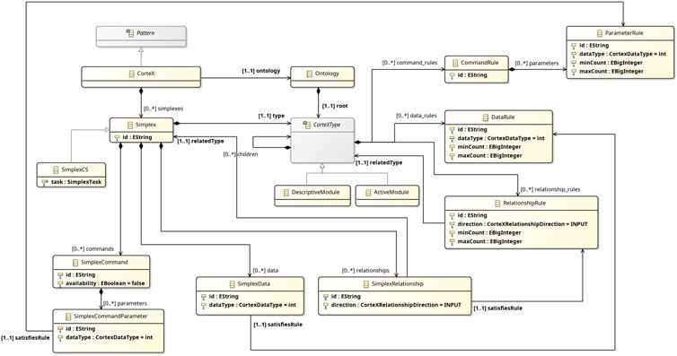
FIGURE 10. Metamodel of CorteX for integration with RoboArch.
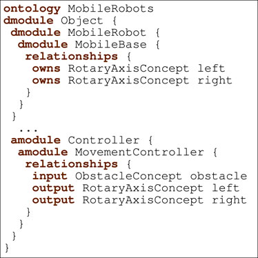
Listing 3. Mobile robots ontology.
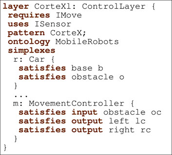
Listing 4. Example of layer using the CorteX pattern with MobileRobots ontology.
As discussed in Caliskanelli et al. (2021, pp. 317–319), a CorteX application is parameterised by an ontology, represented here by the attribute ontology. An object of class
A
A
Listing 3 shows an excerpt of the ontology for the example. It includes descriptive modules, such as MobileBase, and active modules, such as MovementController. MobileBase represents a two-wheeled robot and contains two concepts of type RotaryAxisConcept, which represent the data associated with the left and right wheels. The module MovementController specifies an input concept of type ObstacleConcept and two output concepts of type RotaryAxisConcept (both of these concepts are specified in the ontology as descriptive modules, but omitted in Listing 3).
A
A
A
Listing 4 depicts the RoboArch control layer CorTeXl that uses the CorteX pattern and refers to the MobileRobots ontology in Listing 3. It requires interfaces IMove and ISensor; the first declares operations setLeftMotorSpeed and setRightMotorSpeed, and the second the event obstacle. Next, CorTeXl specifies its pattern (CorteX) and the pattern’s components. These are the ontology (MobileRobots) and the set of simplexes. Each simplex has a name and a type from the ontology, and information about how the ontology relationship rules are satisfied. For instance, MovementController has name m and specifies three relationships; the first specifies that the relationship rule left (of the module MovementController in Listing 3) is satisfied by the simplex lc (declared in the pattern but omitted in Listing 4) of type RotaryAxisConcept.
A
In our CorteX metamodel, we omit the concept of a ClusterCS, which is related to allocation of simplexes to computational units. This is an issue not covered in RoboStar technology. Automatic generation of CorteX code may, for example, define a simple default allocation of simplexes to a single computational unit for further elaboration by the CorteX designer later.
Additionally, we omit the notion of Simplex Trees. These are sets of simplexes, which are represented in our metamodel by the attribute
There are three well-formedness conditions that apply to a
C1 The
C2 The
C3 The
For designs that satisfy these restrictions, we can define a RoboChart sketch via transformation rules. The semantics of the CorteX pattern would be specified in RoboChart in line with the semantics of RoboArch. Each descriptive
As indicated in Figure 3, a layer contains input and output events for inter-layer communication. CorteX, on the other hand, does not use the same communication mechanism and requires a component to transform and route data between the layer and the CorteX application. This component can also be automatically generated similarly to how the semantics of RoboArch specifies the
To conclude, by allying RoboArch and CorteX, we can support the use of CorteX principles from an early stage of design. We can also support verification and automatic code generation. In this way, we further the CorteX agenda by supporting the development of traceable evidence of core properties of applications. Future work will consider significant case studies and automation.
Publicly available additional rules were used in this study. They can be found at: https://robostar.cs.york.ac.uk/publications/reports/roboarch_rules.pdf.
WB, AC, and AM contributed to conception and design of the work. WB took a lead in its execution: definition of metamodel, well-formedness conditions, and transformations. WB wrote the first draft of Sections 1–4; we all contributed to the draft and its revision, and read and approved the submitted version.
The work is funded by the United Kingdom EPSRC Grants EP/M025756/1, EP/R025479/1, and EP/V026801/2, and by the United Kingdom Royal Academy of Engineering Grant No CiET1718/45.
The authors declare that the research was conducted in the absence of any commercial or financial relationships that could be construed as a potential conflict of interest.
All claims expressed in this article are solely those of the authors and do not necessarily represent those of their affiliated organizations, or those of the publisher, the editors and the reviewers. Any product that may be evaluated in this article, or claim that may be made by its manufacturer, is not guaranteed or endorsed by the publisher.
1robostar.cs.york.ac.uk/robotool/
2Laboratory for Analysis and Architecture of Systems CNRS.
3https://robostar.cs.york.ac.uk/case_studies/
4https://robostar.cs.york.ac.uk/publications/reports/roboarch_rules.pdf
5https://robostar.cs.york.ac.uk/publications/reports/roboarch_rules.pdf
Alami, R., Chatila, R., Fleury, S., Ghallab, M., and Ingrand, F. (1998). An architecture for autonomy. Int. J. Rob. Res. 17, 315–337. doi:10.1177/027836499801700402
Albus, J. S., Lumia, R., Fiala, J., and Wavering, A. J. (1989). “Nasrem – The NASA/NBS standard reference model for telerobot control system architecture,” in Industrial robots.
Álvarez, B., Sánchez-Palma, P., Pastor, J. A., and Ortiz, F. (2006). An architectural framework for modeling teleoperated service robots. Robotica 24, 411–418. doi:10.1017/s0263574705002407
Ando, N., Suehiro, T., and Kotoku, T. (2008). “A software platform for component based rt-system development: Openrtm-aist,” in Simulation, modeling, and programming for autonomous robots. Editors S. Carpin, I. Noda, E. Pagello, M. Reggiani, and O. von Stryk (Springer), 87–98.
Arkin, R. C. (1989). Motor schema — Based mobile robot navigation. Int. J. Rob. Res. 8, 92–112. doi:10.1177/027836498900800406
Arkin, R. C. (1987). Towards cosmopolitan robots: Intelligent navigation in extended man-made environments. Ph.D. thesis. Amherst: University of Massachusetts.
Backes, P., Edelberg, K., Vieira, P., Kim, W., Brinkman, A., Brooks, S., et al. (2018). “The intelligent robotics system architecture applied to robotics testbeds and research platforms,” in IEEE aerospace conference (IEEE Computer Society).
Bass, L., Clements, P., and Kazman, R. (2012). Software architecture in practice. Upper Saddle River, NJ: Pearson Education.
Bonasso, R. P., Firby, R. J., Gat, E., Kortenkamp, D., Miller, D. P., and Slack, M. G. (1997). Experiences with an architecture for intelligent, reactive agents. J. Exp. Theor. Artif. Intell. 9, 237–256. doi:10.1080/095281397147103
Bonasso, R. P. (1991). “Integrating reaction plans and layered competences through synchronous control,” in 12th international joint conference on artificial intelligence (San Francisco, CA: Morgan Kaufmann Publishers Inc.), 1225–1231.
Bonasso, R. P., Kerri, R., Jenks, K., and Johnson, G. (1998). “Using the 3T architecture for tracking shuttle RMS procedures,” in IEEE international joint symposia on intelligence and systems.
Bonato, V., and Marques, E. (2009). Roboarch: A component-based tool proposal for developing hardware architecture for mobile robots. IEEE Int. Symposium Industrial Embed. Syst., 249–252.
Borrelly, J.-J., Coste-Manière, E., Espiau, B., Kapellos, K., Pissard-Gibollet, R., Simon, D., et al. (1998). The ORCCAD architecture. Int. J. Rob. Res. 17, 338–359. doi:10.1177/027836499801700403
Brooks, R. A. (1986). A robust layered control system for a mobile robot. IEEE J. Robot. Autom. 2, 14–23. doi:10.1109/jra.1986.1087032
Bruyninckx, H., Klotzbücher, M., Hochgeschwender, N., Kraetzschmar, G., Gherardi, L., and Brugali, D. (2013). “The BRICS component model: A model-based development paradigm for complex robotics software systems,” in 28th annual ACM symposium on applied computing (New York, NY: ACM), 1758–1764.
Bruyninckx, H. (2001). Open robot control software: The orocos project. IEEE Int. Conf. Robotics Automation 3, 2523–2528.
Caliskanelli, I., Goodliffe, M., Whiffin, C., Xymitoulias, M., Whittaker, E., Verma, S., et al. (2021). CorteX: A software framework for interoperable, plug-and-play, distributed, robotic systems of systems. Springer, 295–344.
Cavalcanti, A. L. C., Barnett, W., Baxter, J., Carvalho, G., Filho, M. C., Miyazawa, A., et al. (2021a). RoboStar Technology: A roboticist’s toolbox for combined proof, simulation, and testing. Springer International Publishing, 249–293. doi:10.1007/978-3-030-66494-7_9
Cavalcanti, A. L. C., Dongol, B., Hierons, R., Timmis, J., and Woodcock, J. C. P. (Editors) (2021b). Software engineering for robotics (Springer International Publishing). doi:10.1007/978-3-030-66494-7
Cavalcanti, A. L. C., Sampaio, A. C. A., Miyazawa, A., Ribeiro, P., Filho, M. C., Didier, A., et al. (2019). Verified simulation for robotics. Sci. Comput. Program. 174, 1–37. doi:10.1016/j.scico.2019.01.004
Chatila, R., Lacroix, S., Simeon, T., and Herrb, M. (1995). Planetary exploration by a mobile robot: Mission teleprogramming and autonomous navigation. Auton. Robots 2, 333–344. doi:10.1007/bf00710798
Chien, S., Knight, R., Stechert, A., Sherwood, R., and Rabideau, G. (2000). “Using iterative repair to improve the responsiveness of planning and scheduling,” in 5th international conference on artificial intelligence planning systems (Menlo Park, CA: AAAI Press), 300–307.
Chitta, S., Marder-Eppstein, E., Meeussen, W., Pradeep, V., Tsouroukdissian, A. R., Bohren, J., et al. (2017). ros_control: A generic and simple control framework for ROS. J. Open Source Softw. 2, 456. doi:10.21105/joss.00456
Corke, P., Sikka, P., Roberts, J. M., and Duff, E. (2004). “Ddx : A distributed software architecture for robotic systems,” in Australasian conference on robotics & automation. Editors N. Barnes,, and D. Austin (Sydney, NSW: Australian Robotics & Automation Association).
Dhouib, S., Kchir, S., Stinckwich, S., Ziadi, T., and Ziane, M. (2012). Simulation, modeling, and programming for autonomous robots. SpringerSimulate and Deploy Robotic Applications, 149–160. chap. RobotML, a Domain-Specific Language to Design.
Firby, R. J., Kahn, R. E., Prokopowicz, P. N., and Swain, M. J. (1995a). “An architecture for vision and action,” in 14th Int. Jt. Conf. Artif. Intell. San Francisco, CA: Morgan Kaufmann Publishers Inc., 1, 72–79.
Firby, R. J., Slack, M. G., and Drive, C. (1995b). “Task execution: Interfacing to reactive skill networks,” in Lessons learned from implemented software architectures for physical agents: Papers from the 1995 spring symposium. Editor K. D. H. Henry, 97–111. Technical Report SS-95-02.
Franz, T., Lüdtke, D., Maibaum, O., and Gerndt, A. (2018). Model-based software engineering for an optical navigation system for spacecraft. CEAS Space J. 10, 147–156. doi:10.1007/s12567-017-0173-5
Gamma, E., Helm, R., Johnson, R., and Vlissides, J. (1995). Design patterns - elements of reusable object-oriented software. Addison-Wesley.
García, S., Menghi, C., Pelliccione, P., Berger, T., and Wohlrab, R. (2018). An architecture for decentralized, collaborative, and autonomous robots. IEEE Int. Conf. Softw. Archit., 75–7509.
Gat, E. (1992). “Integrating planning and reacting in a heterogeneous asynchronous architecture for controlling real-world mobile robots,” in 10th national conference on artificial intelligence (Menlo Park, CA: AAAI Press), 809–815.
Huntsberger, T., and Woodward, G. (2011). OCEANS’11 MTS/IEEE KONA, 1–10. Intelligent autonomy for unmanned surface and underwater vehicles.
Li, W., Ribeiro, A. M. P., Cavalcanti, A. L. C., Woodcock, J. C. P., and Timmis, J. (2018). From formalised state machines to implementations of robotic controllers. Springer International Publishing, 517–529. doi:10.1007/978-3-319-73008-0_36
Luckcuck, M., Farrell, M., Dennis, L. A., Dixon, C., and Fisher, M. (2019). Formal specification and verification of autonomous robotic systems: A survey. ACM Comput. Surv. 52, 1–41. doi:10.1145/3342355
Luzeaux, D., and Dalgalarrondo, A. (2001). “HARPIC, an hybrid architecture based on representations, perceptions, and intelligent control: A way to provide autonomy to robots,” in Computational science (Springer), 327–336.
Lyons, D. M., and Hendriks, A. J. (1995). Planning as incremental adaptation of a reactive system. Robotics Aut. Syst. 14, 255–288. doi:10.1016/0921-8890(94)00033-x
Metta, G., Fitzpatrick, P., and Natale, L. (2006). Yarp: Yet another robot platform. Int. J. Adv. Robotic Syst. 3, 8. doi:10.5772/5761
Miyazawa, A., Ribeiro, P., Li, W., Cavalcanti, A. L. C., and Timmis, J. (2017). Automatic property checking of robotic applications. IEEE/RSJ Int. Conf. Intelligent Robots Syst., 3869–3876. doi:10.1109/IROS.2017.8206238
Miyazawa, A., Ribeiro, P., Li, W., Cavalcanti, A. L. C., Timmis, J., and Woodcock, J. C. P. (2019). RoboChart: Modelling and verification of the functional behaviour of robotic applications. Softw. Syst. Model. 18, 3097–3149. doi:10.1007/s10270-018-00710-z
Miyazawa, A., Ribeiro, P., Ye, K., Cavalcanti, A. L. C., Li, W., Timmis, J., et al. (2020). RoboChart: Modelling, verification and simulation for robotics. York, UK: Tech. rep., University of York, Department of Computer Science. Available at www.cs.york.ac.uk/robostar/notations/.
Muratore, L., Laurenzi, A., Hoffman, E. M., Rocchi, A., Caldwell, D. G., and Tsagarakis, N. G. (2017). Xbotcore: A real-time cross-robot software platform. IEEE Int. Conf. Robotic Comput., 77–80.
Muscettola, N., Nayak, P. P., Pell, B., and Williams, B. C. (1998). Remote agent: To boldly go where no AI system has gone before. Artif. Intell. 103, 5–47. doi:10.1016/s0004-3702(98)00068-x
Musliner, D. J., Durfee, E. H., and Shin, K. G. (1993). Circa: A cooperative intelligent real-time control architecture. IEEE Trans. Syst. Man. Cybern. 23, 1561–1574. doi:10.1109/21.257754
Nesnas, I. A. D., Simmons, R., Gaines, D., Kunz, C., Diazcalderon, A., Estlin, T., et al. (2006). CLARAty: Challenges and steps toward reusable robotic software. Int. J. Adv. Robotic Syst. 3, 5–030. doi:10.5772/5766
Nordmann, A., Hochgeschwender, N., Wigand, D., and Wrede, S. (2016). A survey on domain-specific modeling and languages in robotics. J. Softw. Eng. Robotics 7, 75–99.
Sanchez-Lopez, J. L., Molina, M., Bavle, H., Sampedro, C., Fernández, R. A. S., and Campoy, P. (2017). A Multi-Layered Component-Based approach for the development of aerial robotic systems: The aerostack framework. J. Intell. Robot. Syst. 88, 683–709. doi:10.1007/s10846-017-0551-4
Sellner, B., Heger, F. W., Hiatt, L. M., Simmons, R., and Singh, S. (2006). Coordinated multiagent teams and sliding autonomy for large-scale assembly. Proc. IEEE 94, 1425–1444. doi:10.1109/jproc.2006.876966
Siciliano, B., and Khatib, O. (Editors) (2016). Springer handbook of robotics (Springer Handbooks Springer).
Silva, L., Yan, R., Ingrand, F., Alami, R., and Bensalem, S. (2015). “A verifiable and correct-by-construction controller for robots in human environments,” in 10th annual ACM/IEEE international Conference on human-robot interaction extended abstracts (ACM), HRI’15 extended abstracts, 281.
Stamper, D., Lotz, A., Lutz, M., and Schlegel, C. (2016). The SmartMDSD toolchain: An integrated MDSD workflow and integrated development environment (IDE) for robotics software. J. Softw. Eng. Robotics 7, 3–19.
Volpe, R., Nesnas, I., Estlin, T., Mutz, D., Petras, R., and Das, H. (2001). The CLARAty architecture for robotic autonomy. IEEE Aerosp. Conf. 1.
Wigand, D. L., Mohammadi, P., Hoffman, E. M., Tsagarakis, N. G., Steil, J. J., and Wrede, S. (2018). “An open-source architecture for simulation, execution and analysis of real-time robotics systems,” in IEEE international conference on simulation, modeling, and programming for autonomous robots, 93–100.
Wong, C., Kortenkamp, D., and Speich, M. (1995). “A mobile robot that recognizes people,” in 7th IEEE international conference on tools with artificial intelligence, 346–353.
Woodcock, J. C. P., and Davies, J. (1996). Using Z - specification, refinement, and proof. Prentice-Hall.
Ye, K., Cavalcanti, A. L. C., Foster, S., Miyazawa, A., and Woodcock, J. C. P. (2021). Probabilistic modelling and verification using RoboChart and PRISM. Softw. Syst. Model. 21, 667–716. doi:10.1007/s10270-021-00916-8
Keywords: software engineering, patterns, RoboStar framework, nuclear industry, verification, simulation, test, proof
Citation: Barnett W, Cavalcanti A and Miyazawa A (2022) Architectural modelling for robotics: RoboArch and the CorteX example. Front. Robot. AI 9:991637. doi: 10.3389/frobt.2022.991637
Received: 11 July 2022; Accepted: 23 September 2022;
Published: 28 October 2022.
Edited by:
Rob Skilton, United Kingdom Atomic Energy Authority, United KingdomReviewed by:
Domenico Redavid, University of Bari Aldo Moro, ItalyCopyright © 2022 Barnett, Cavalcanti and Miyazawa. This is an open-access article distributed under the terms of the Creative Commons Attribution License (CC BY). The use, distribution or reproduction in other forums is permitted, provided the original author(s) and the copyright owner(s) are credited and that the original publication in this journal is cited, in accordance with accepted academic practice. No use, distribution or reproduction is permitted which does not comply with these terms.
*Correspondence: Ana Cavalcanti, QW5hLkNhdmFsY2FudGlAeW9yay5hYy51aw==
Disclaimer: All claims expressed in this article are solely those of the authors and do not necessarily represent those of their affiliated organizations, or those of the publisher, the editors and the reviewers. Any product that may be evaluated in this article or claim that may be made by its manufacturer is not guaranteed or endorsed by the publisher.
Research integrity at Frontiers
Learn more about the work of our research integrity team to safeguard the quality of each article we publish.