 Dawit Assfaw
 Solomon Seid
95% of researchers rate our articles as excellent or good
Learn more about the work of our research integrity team to safeguard the quality of each article we publish.
Find out more
ORIGINAL RESEARCH article
Front. Robot. AI , 19 May 2022
Sec. Biomedical Robotics
Volume 9 - 2022 | https://doi.org/10.3389/frobt.2022.870018
This article is part of the Research Topic Lighter and More Efficient Robotic Joints in Prostheses and Exoskeletons: Design, Actuation and Control View all 5 articles
A large number of transfemoral amputees living in low-income countries could not access a much-needed prosthesis. Hence, affordable semi-active prosthetic knees have been designed in recent years. As the swing phase of the gait cycle is unstable as compared to the stance phase, these designs could not perfectly mimic this phase of a healthy human being. In contribution toward such a gap, this study proposes the modeling and design of a robust controller for magnetorheological (MR) damper-based semi-active prosthetic knee. A dynamic model representation for the swing phase of the single-axis knee is derived first. Subsequently, an MR damper valve model is developed. Then, a higher-order sliding mode controller is designed and evaluated for its stability and performance. The numerical simulation results show that the super twisting sliding mode controller improves the semi-active prosthetic knee’s tracking efficiency. The design exhibited the finest performance, providing a low normalized mean square error as compared to previous designs. The variable speed performance and robustness evaluation for this controller also showed its ability to continue providing excellent performance in the presence of disturbances.
Transfemoral amputation is among the types of leg amputation which occur between the hip and knee joints. A recent study by the World Health Organization (WHO) states that 35–40 million amputees are living in developing countries, with knee amputation being the most common one. The most familiar causes of physical disabilities include traffic accidents, natural disasters, war, and the like. Those people with leg amputation will have reduced ability to move. Hence, a prosthetic knee is required to substitute the amputee limb to enhance the quality of their life by assisting them in performing activities such as standing and walking like wholesome people.
Throughout the years of prosthetic knee development, three types of knees have been studied to date, namely, active (powered), semi-active (adjustable damping), and mechanically operated passive prosthetic knees. The active prosthetic knee has its power supply to operate effectively. Amputees having this prosthetic knee will be able to perform complex activities such as walking up stairways and standing up. However, the main drawback of this prosthetic knee is its consumption of a large amount of energy and a large actuator, which leads to a heavy weight and reduction of battery life (Ekkachai and Nilkhamhang, 2016).
In contrast, mechanically passive knees do not need a power supply to function. They only provide a constant amount of damping suitable for only one speed of walking. Semi-active knees have several advantages over mechanically operated passive prosthetics, including improved knee stability, the capacity to change the walking pace, and the ability to react to changing environmental conditions (Ekkachai and Nilkhamhang, 2016).
Semi-active knees are mostly known for their use of magnetorheological (MR) fluid (MRF)-based mechanisms, for instance, MR dampers. As mechanically passive prosthetic knees cannot change damping values, they expose amputees to health problems and injuries using MRF-based dampers on prosthetic limbs, which deliver an extensive dynamic range and will avoid these conditions from occurring. Since an MR damper has a lot of advantages such as a small volume, a simple structure, low power consumption, and large resistance, it is considered to be a good alternative for the semi-active control of prosthetic limbs (Xie et al., 2015).
The prosthetic knees incorporating readily made MR dampers designed and manufactured by Lord Corporation have some drawbacks. Hence, the main purpose of the author (Seid et al., 2019b) was to propose an integrated design to address the drawbacks of these MRD-based prosthetic knees. This study has developed the overall design of prosthetic knees controlled by MRD. The swing-phase dynamic system modeled the knee and MR damper so that the control parameters are optimized using the constrained nonlinear optimization technique; then, the swing-phase trajectory produced by the MRD-based knee with optimized control parameters was compared with a healthy human swing-phase trajectory from experimental data. However, the work was not microcontroller-based and variable walking speed characteristics of the knee were not studied.
In another research, (Zuo et al., 2021), a second-order sliding mode controller was designed to control both the swing and stance periods of a transfemoral prosthetic knee. In the research, an MRD was designed and used as a controlling and damping force-providing mechanism. The work considered a flat ground walking condition at a 4.68 kmph walking speed. The design was tested in real-life applications using a prototype. The results show that the knee angle trajectory has a relatively high error of 9°. Even if the result is as close as the desired knee angle, the work did not consider the performance of the controller at various speeds, and the robustness was not checked for different walking conditions and walking speeds.
Another promising work (Ekkachai et al., 2014) proposed a new control algorithm for the swing phase of the variable damping prosthetic knee. This work applied neural network predictive control for the prosthetic knee, and the algorithm was tested at various walking speeds. It comprises a feedforward neural network (FNN) structured swing-phase model and predictive control which is optimized by a constrained nonlinear optimization technique. The constructed NNPC attempts to solve the setback of the MR damper, which was capable of only supplying a damping force, whereas the normal gait cycle needs active and damping forces simultaneously. The NNPC is capable of estimating the expected knee angle trajectory with a specified amount of command voltage input. However, it could not be applied in a real-world application (online) since it requires too much computation time.
The previous study by the author (Seid et al., 2016) considered the design and evaluations of two types of swing phase controllers, namely, an MRF-based damper and hydraulic damper, for the single-axis knee to control its swing phase. The assessment outcomes indicate a better capability of the MR damper over that of the hydraulic one. However, this research did not consider utilizing a microcontroller, and the controlling parameters of the damper were not checked for its performance while walking on a relatively rough terrain, jumping, and climbing and at variable walking speeds. Furthermore, the dynamic model of the single-axis knee proposed in this study did not consider the effect of the thigh angle while checking the performance of the designed MR damper. Hence, a modified model has to be developed to fully describe the relationship between the thigh and shank angle.
To solve the drawbacks which are found in most of the semi-active prosthetic knees, the authors (Seid et al., 2017; Seid et al., 2019b) have previously proposed a design model of an MR actuator for the prosthetic knee application as a swing-phase controller for amputees on a ground level walk. The proposed design shows its efficiency in closely mimicking the swing-phase trajectory of a healthy human being; however, for the amputee to walk on various terrains and walking scenarios, the designed damper should provide variable damping at various speeds since different terrains and walking speeds require a variable damping force to avoid the exposure of the amputees to walking discomfort leading to injuries and health problems, that is, due to undamped forces on the hip joint. Hence, a robust controller is required.
A modified dynamic model for the single-axis knee is developed by using Lagrangian mechanics in Section 2. Then, the resulting MRF is analyzed using the Bingham Plastic model accordingly in Section 3. Following this, Section 4 presents the design of super twisting SMC and its simulation on MATLAB. In Section 5, simulation results and comparisons are given and analyzed to verify the designed controller’s efficiency. Section 5 provides a discussion on the simulation results presented in Section 5. Finally, Section 7 concludes the article.
During a regular gait cycle, cyclic occurrences can be seen when walking on a level terrain. Toe-off and foot strike are the two different occurrences that can distinguish the periodic pattern. One gait cycle is classified into two main phases/periods: stance and swing (Figure 1, right leg shaded). Stance is the time between when the foot first meets the ground and when it rises from it, and it accounts for 62% of the gait cycle. The rest 38% of the gait cycle is made up of the swing period when the foot leaves the ground and swings in the air (Nandy et al., 2012).
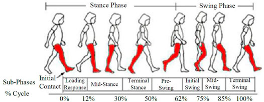
FIGURE 1. Gait cycle (Nandy et al., 2012).
The dynamic model of the swing-phase leg model with the prosthetic knee, depicted in Figure 2, is developed based on the following assumptions:
• The ankle is considered rigid and fixed on the shank, and the shank and thigh are assumed to be connected by pin joints.
• The thigh is allowed to have vertical and horizontal movement in two dimensions.
• The swing motion of the two-link rigid body chain is taken as a two-degree-of-freedom double pendulum.
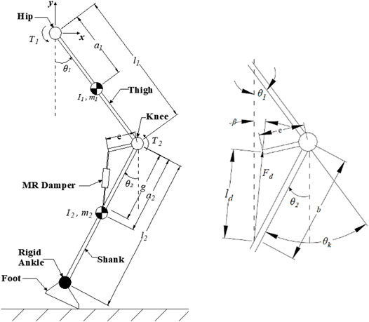
FIGURE 2. Swing-phase model and damper force and angle resolution.
The resulting swing-phase representation of the knee by applying Lagrangian formulation will be
From this relation, the inertia, Coriolis and centrifugal, and gravitational matrices are as follows:
where
From the damper resolution, the angle the damping force makes with the vertical axis is derived from the aforementioned figure to be
where e is the extension length of the damper from the knee joint, b is the distance where the base of the damper is attached on the shank from the knee joint, and
MRFs are members of the family of fluids whose properties are governed by the strength of the magnetic field. When subjected to a magnetic field, MRFs can convert from a linear viscous liquid to semi-solids, with the yield strength being controlled quickly and constantly. When a magnetic field is supplied to the suspended particles, they become polarized and migrate, reducing the ensemble’s stored energy. As the employed magnetic field increases, the energy desired to yield those chain-like arrangements will increase, making the fluid rigid to flow (Guglielmino et al., 2008).
Modeling MRF involves dealing with the rheological behavior of these materials in pre-yield and post-yield regimes. Two models have been used popularly to represent MRF models.
A quasi-static Bingham plastic model supposes that the fluid exhibits a shear stress comparative to the shear rate in the post-yield region, expressed by the following equations:
where
The Bingham plastic model does not consider the change of the viscosity of the fluid when the applied magnetic field varies; hence, another model was developed. The variation of viscosity in the post-yield region is clearly described by a more accurate Herschel–Bulkley model. When the MRF undergoes an increased shear rate, this model predicts post-yield shear thinning or thickening (Guglielmino et al., 2008; Seid et al., 2019b). The Herschel–Bulkley model is represented as follows:
where K is the consistency index, m is the MRF behavior index, and
Following the development of the MRF model, the modeling of the MR valve is described, supposing that the MRF displays Bingham plastic characteristics and that the flow in the valve paths is completely developed. The schematic diagram of the MR damper and its single-coil valve is shown in Figure 3.
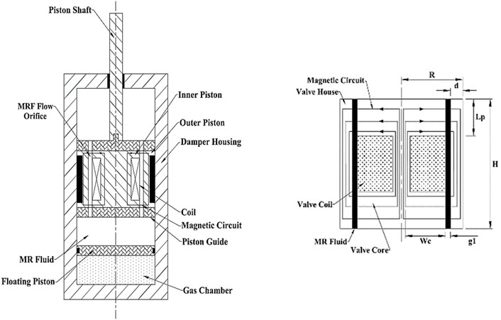
FIGURE 3. Diagram of MRD and the MR valve (Seid et al., 2019a).
Flow resistance which is dependent on the magnetic field is caused by magnetic field lines that are orthogonal toward the MRF’s direction of flow. A considerable amount of pressure drop is inevitable while the fluid passes through the valve, represented by Jolly et al. (1999)
In Eq. 7,
The damping force produced by the damper is presented by using the following equation:
Here, Ap and Ar are the piston and rod areas of the damper, respectively, and P1 and P2 represent the pressures in the lower and upper chambers, respectively. Now substituting Eq. 7into Eq 10,weget.
Finally, the most important parameter in controlling the damping force, yield stress (field-dependent) with respect to the employed field intensity,
where
From this optimal design of the MR damper valve, the curve-fitting relationship between the input current and yield stress can be derived to be
Classified under the VSCS category, the sliding mode controller is by far one of the most robust controllers, with the characteristics of switching its control law that leads the system states to the anticipated sliding surface (Edwards, Alwi and Hamayun, 2018). Conventional sliding mode controllers operate by applying discontinuous high-frequency switching. However, high-frequency switching control needs to be reduced as much as possible, and continuous control is a better choice. Hence, super twisting SMC will be designed to overcome the drawbacks (Shtessel et al., 2014).
Now, the sliding variable can be defined using the following equation:
To derive the aforementioned sliding variable to zero in a finite amount of time, the following continuous control law can be applied:
The compensated sliding variable dynamics will be
The specified control u forces the sliding variable to nil in a finite amount of time, tr. On the other hand, when
where
However, due to the presence of a disturbance term, the sliding variable dynamics will fail to converge to zero using the disturbance-freederived control law of the form in Eq. 14; hence, it is desirable to add a term (w) in Eq. 14 so that it follows the disturbance term,
In this study, the error dynamics will be described by the following equation:
The simulation of the designed controllers proceeds in place. The schematic block diagram used in the simulation of the controller’s performance is provided in Figure 4 below.
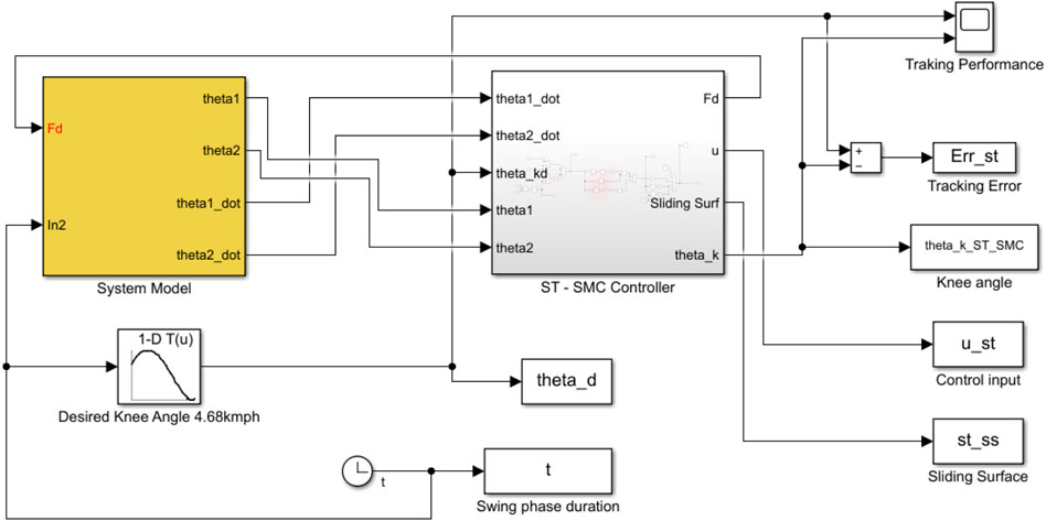
FIGURE 4. SIMULINK block diagram of the system model and ST-SMC controller.
The physical parameters of an average human being with a mass of 56.7 kg are listed in Table 1.
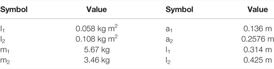
TABLE 1. Physical parameter of a healthy human being (Seid et al., 2016).
Considering the dynamic system model, the results of trailing performance and tracking error of the controller at a 4.68 kmph walking speed are shown in Figures 5, 6.
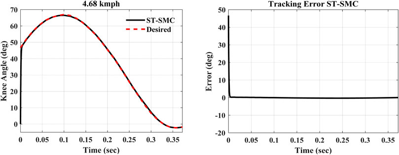
FIGURE 5. Tracking performance and error of the controller.
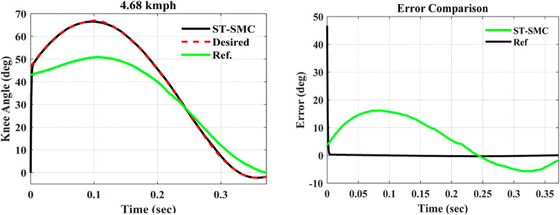
FIGURE 6. Comparison of tracking efficiency and error with the former design.
The simulations were performed over the swing-phase period of the gait cycle, that is, for 0.372 s. Now comparing with the simulation study result obtained from the previously designed model by Seid et al. (2016) presented in green, the results in Figure 6 are obtained. As is shown from the error comparison graph, the previous mechanically designed knee exhibited a large deviation from the desired trajectory. On the other hand, the ST-SMC-controlled MR damper with the modified dynamic model has tracked the knee angle trajectory of a healthy human being with a minimum error (between 0.2145 and –0.2981°), as seen from the error comparison graph earlier.
Now the controller’s simulation outputs of the maximum flexion angle, the period of the swing phase, the shank velocity at the end of the swing phase, and the normalized mean square error (NRMSE) can be contrasted with the former design, as seen in Table 2.
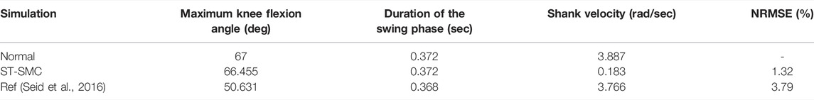
TABLE 2. Comparison of results with Ref Seid et al., 2016.
As is clearly shown in the table, Table 2, the ST-SMC-based prosthetic knee has shown a minimized NRMSE compared to the formerly designed one. The shank velocity by the end of the swing phase was reduced as well. This minimum angular velocity is crucial since it has to be kept as small as possible so that it will be easily stopped when it reaches the end of the swing phase without the presence of excessive impact due to the use of a rubber bumper. The knee flexion angle is also close to the desired one with a minimal error.
Instabilities occur, mainly, when amputees walk on a rough terrain, and the road irregularities will expose them to vibration, causing the controller to face instabilities. Unless the controller is robust, this causes the controller to be less efficient in mimicking the normal gait cycle of a healthy human being.
In this research, two major causes of disturbances had been applied to the system model, that is, on the vertical and horizontal hip accelerations of the amputee. When amputees face a sudden increase or decrease in their forward motion, the hip horizontal acceleration will vary considerably. Furthermore, similar variable vertical acceleration will occur as amputees face irregularities on their walkways. For this evaluation, the ideal hip horizontal and vertical accelerations are curve-fitted by applying the following equations obtained using a curve-fitting tool on MATLAB
where:
To represent the disturbances that occurred due to the aforementioned reasons, the amplitudes and frequencies of the aforementioned curve-fitted formulas of hip accelerations are scaled independently and simultaneously as plotted in Figure 7.
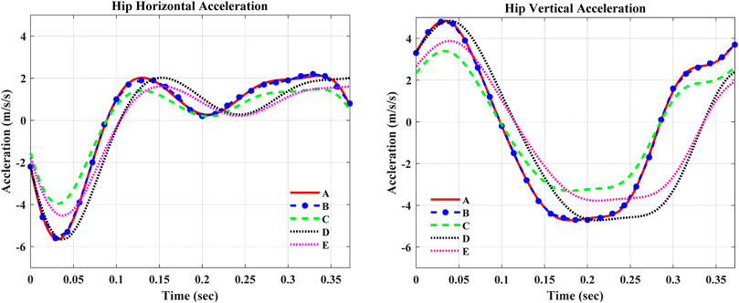
FIGURE 7. Curve-fitted and scaled data of hip acceleration. In the figures, A—Curve-fitted data (without scaling), B—Experimental data from Winter (2009), C—Curve-fitted data with 70% amplitude scaling, D—Curve-fitted data with 85% frequency scaling, and E—Curve-fitted data with 80% amplitude and 85% frequency scaling.
The robustness evaluation of ST-SMC was performed considering a disturbance due to the rough walking terrain as shown in Table 3. The analysis was performed by applying the amplitude and frequency scaling on the curve-fitted experimental data of vertical and horizontal hip accelerations. The analysis outputs depicted that the ST-SMC was exceptionally robust and stable, exhibiting a minimal error in tracking the desired swing-phase knee angle trajectory.
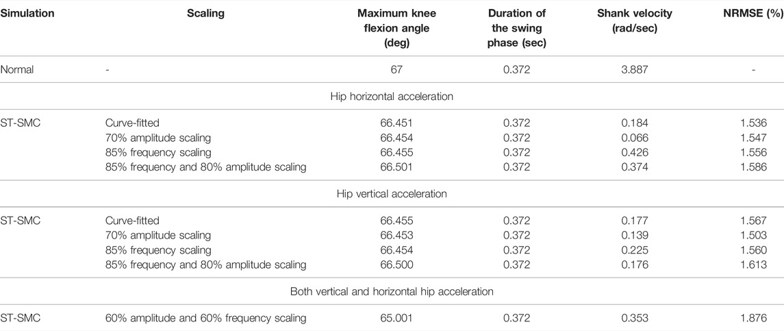
TABLE 3. Robustness evaluation.
The simulation outputs in Table 3 show that the super twisting SMC was robust against the applied disturbances in the swing phase of the gait cycle. It was seen that the controller continues its tracking with a minimum deviation, that is, a small NRMSE, from the desired knee angle trajectory. On the other hand, further investigation of robustness was made by manipulating both the horizontal and vertical accelerations at the same time. The super twisting SMC still maintains its robustness with a minimum NRMSE and end phase velocity. Figure 8 shows the 60% amplitude and frequency scaling of hip accelerations.
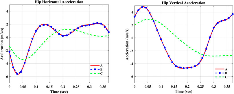
FIGURE 8. Curve-fitted and scaled data of hip acceleration. In the figures, A—Curve-fitted data (without scaling), B—Experimental data from Winter (2009), and C—Curve-fitted data with 60% amplitude and frequency scaling.
Furthermore, the various walking speed performances of the ST-SMC showed that it keeps tracking the desired knee angle trajectory at those various walking speeds with a minimized tracking error. Figure 9 shows the knee angle trajectory of a healthy human gait over the course of the swing phase.
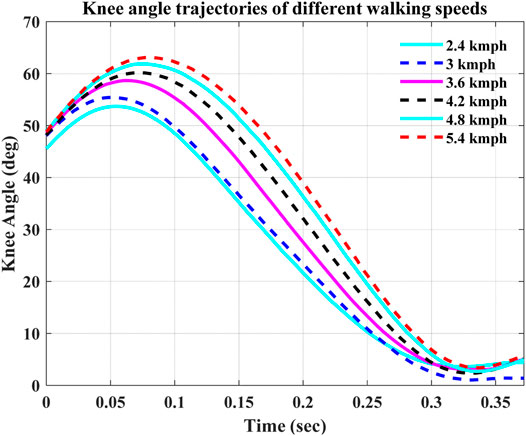
FIGURE 9. Knee angle trajectories at different walking speeds (Ekkachai et al., 2014).
In Table 4, the NRMSE was calculated to find the error depicted by the controller while operating at different walking speeds. The results will be compared with the former design as well.
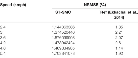
TABLE 4. NRMSE comparison.
As is seen from the NRMSE calculation, the developed controller on the modified system model showed a better efficiency in tracking the desired knee angles at different speeds. On the other hand, the comparison of the controllers with previously designed prosthetic knees shows that the ST-SMC provided a better result while tracking the desired knee angle with a minimum error.
The computer simulation findings of the controller applied on the modified mathematical models are presented. It is seen that at a walking speed of 4.68 kmph, the designed controller displayed an excellent performance as compared to the results found in the former mechanically designed prosthetic knees by Seid et al. (2016). The evaluation of various speed efficiencies of controllers was also executed and compared with previous work by Ekkachai et al.(2014).
Furthermore, the robustness of ST-SMC was evaluated considering a disturbance due to the rough walking terrain. The analysis was performed by applying the amplitude and frequency scaling on the curve-fitted experimental data of vertical and horizontal hip accelerations. The analysis outputs depicted that the ST-SMC was exceptionally robust compared to the previous design by Seid et al. (2016) and stable, exhibiting a minimal error in tracking the desired swing-phase knee angle trajectory of a healthy human being.
This study presented the design and simulation of ST-SMC for a transfemoral prosthetic knee. The dynamic system models and the MR damper model were developed using the Lagrangian mechanics and Bingham Plastic model, respectively. The relation between the yield shear stress and input current of MRF is obtained from an optimized MR damper valve design. It was observed that super twisting SMC provided a superior tracking efficiency with a reduced NRMSE of 1.32 and chattering compared to the previously designed prosthetic knee. In addition, the final shank velocity of the prosthetic knee was reduced to 0.183 rad/sec and the maximum flexion angle near to the natural gait.
Moreover, the measure of the robustness of the designed ST-SMC was performed by applying different walking speeds and several disturbances related to the rough terrain. This research had a significant contribution in designing a more stable system model controlled with ST-SMC showing negligible chattering and increased robustness. Future work includes evaluating the system with other controllers such as adaptive SMC, nonlinear PID, and integral SMC to minimize exhibited errors. Furthermore, experimental investigation and prototyping of the designed controller will be conducted.
The original contributions presented in the study are included in the article/Supplementary Material, further inquiries can be directed to the corresponding author.
DA designed the super twisting sliding mode controller, ran the simulations, and wrote the manuscript. SS worked on the modeling of the MR damper and the single-axis knee, supervised the whole research work, and reviewed the manuscript.
This research was conducted as a partial fulfillment of the Master of Science degree in Mechatronics Engineering by the fund provided from Addis Ababa Science and Technology University (AASTU), Ethiopia.
The authors declare that the research was conducted in the absence of any commercial or financial relationships that could be construed as a potential conflict of interest.
All claims expressed in this article are solely those of the authors and do not necessarily represent those of their affiliated organizations or those of the publisher, the editors, and the reviewers. Any product that may be evaluated in this article or claim that may be made by its manufacturer is not guaranteed or endorsed by the publisher.
Edwards, C., Alwi, H., and Hamayun, M. T. (2018). “Fault Tolerant Control Using Integral Sliding Modes,” in Studies in Systems, Decision and Control. Editor J. Kacprzyk. First Edit. (Springer International Publishing Switzerland). doi:10.1007/978-3-319-62896-7_13
Ekkachai, K., and Nilkhamhang, I. (2016). Swing Phase Control of Semi-active Prosthetic Knee Using Neural Network Predictive Control with Particle Swarm Optimization. IEEE Trans. Neural Syst. Rehabil. Eng. 24 (11), 1169–1178. doi:10.1109/TNSRE.2016.2521686
Ekkachai, K., Tantaworrasilp, A., Nithi-Uthai, S., Tungpimolrut, K., and Nilkhamhang, I. (2014). “Variable Walking Speed Controller of MR Damper Prosthetic Knee Using Neural Network Predictive Control,” in Proceedings of the SICE Annual Conference, 513–518. doi:10.1109/SICE.2014.6935208
Guglielmino, E., Sireteanu, T., Stammers, S. W., Ghita, G., and Giuclea, M. (2008). Semi-active Suspension ControlFirst Edit. First Edit. London: Springer-Verlag London Limited. doi:10.1007/978-1-84800-231-9Semi-active Suspension Control
Jolly, M. R., Bender, J. W., and Carlson, J. D. (1999). Properties and Applications of Commercial Magnetorheological Fluids. Journal of Intelligent Material Systems and Structures 10 (1), 5–13. doi:10.1177/1045389X9901000102
Marinca, V., Ene, R.-D., and Bereteu, L. (2017). Application of the Optimal Homotopy Asymptotic Method to Nonlinear Bingham Fluid Dampers. Open Physics 15 (1), 620–626. doi:10.1515/phys-2017-0072
Nandy, A., Mondal, S., Rai, L., Chakraborty, P., and Nandi, G. C. (2012). “A Study on Damping Profile for Prosthetic Knee,” in Proceedings of the International Conference on Advances in Computing, Communications and Informatics, 511–517. doi:10.1145/2345396.2345481
Nguyen, Q.-H., and Choi, S.-B. (2009). Optimal Design of MR Shock Absorber and Application to Vehicle Suspension. Smart Mater. Struct. 18, 035012. doi:10.1088/0964-1726/18/3/035012
Nguyen, Q. H., Choi, S. B., Lee, Y. S., and Han, M. S. (2009). An Analytical Method for Optimal Design of MR Valve Structures. Smart Mater. Struct. 18, 095032. doi:10.1088/0964-1726/18/9/095032
Nguyen, Q. H., Nguyen, N. D., and Choi, S. B. (2014). Optimal Design and Performance Evaluation of a Flow-Mode MR Damper for Front-Loaded Washing Machines. Asia Pac. J. Comput. Engin. 1 (1), 1–14. doi:10.1186/2196-1166-1-3
Seid, S., Chandramohan, S., and Sujatha, S. (2019a). Design and Evaluation of a Magnetorheological Damper Based Prosthetic Knee. Ije 32 (1), 146–152. doi:10.5829/ije.2019.32.01a.19
Seid, S., Chandramohan, S., and Sujatha, S. (2019b). “Design Evaluation of a Mono-Tube Magnetorheological (MR) Damper Valve,” in Lecture Notes in Mechanical Engineering (Springer Singapore), 145–151. doi:10.1007/978-981-13-2718-6_15
Seid, S., Chandramohan, S., and Sujatha, S. (2018). Optimal Design of an MR Damper Valve for Prosthetic Knee Application. J Mech Sci Technol 32 (6), 2959–2965. doi:10.1007/s12206-018-0552-7
Seid, S., Sujatha, S., and Chandramohan, S. (2016). Design and Evaluation of Swing Phase Controllers for Single-axis Knee. International Journal Bioautomation 20 (3), 373–388.
Seid, S., Sujatha, S., and Chandramohan, S. (2017). Performance Evaluation of MR Damper Valve Configurations Using Finite Element Method. International Journal of Engineering, Transactions B: Applications 30 (2), 1216–1223.
Shtessel, Y., Edwards, C., Fridman, L., and Levant, A. (2014). Sliding Mode Control and Observation, Sliding Mode Control and Observation. New York: Springer Science+Business Media New York. doi:10.1007/978-0-8176-4893-0
Winter, D. A. (2009). Biomechanics and Motor Control of Human Movement. Fourth Edition. John Wiley & Sons. doi:10.1002/9780470549148
Xie, H. L., He, N., Li, F., and Yang, J.-Y. (2015). Bionička Konstrukcija I Identifikacija Sustava Inteligentne Bioničke Noge S Magneto-Reološkim Prigušivačem. Tehnicki Vjesnik 22 (5), 1093–1098. doi:10.17559/TV-20150731100315
Keywords: magnetorheological damper, super twisting, sliding mode control, swing phase, semi-active
Citation: Assfaw D and Seid S (2022) Design of a Super Twisting Sliding Mode Controller for an MR Damper-Based Semi-Active Prosthetic Knee. Front. Robot. AI 9:870018. doi: 10.3389/frobt.2022.870018
Received: 05 February 2022; Accepted: 12 April 2022;
Published: 19 May 2022.
Edited by:
Yuanxi Sun, Chongqing University, ChinaReviewed by:
Deepak Joshi, Indian Institutes of Technology (IIT), IndiaCopyright © 2022 Assfaw and Seid. This is an open-access article distributed under the terms of the Creative Commons Attribution License (CC BY). The use, distribution or reproduction in other forums is permitted, provided the original author(s) and the copyright owner(s) are credited and that the original publication in this journal is cited, in accordance with accepted academic practice. No use, distribution or reproduction is permitted which does not comply with these terms.
*Correspondence: Solomon Seid, c29sb21vbnNlaWRAZ21haWwuY29t
Disclaimer: All claims expressed in this article are solely those of the authors and do not necessarily represent those of their affiliated organizations, or those of the publisher, the editors and the reviewers. Any product that may be evaluated in this article or claim that may be made by its manufacturer is not guaranteed or endorsed by the publisher.
Research integrity at Frontiers
Learn more about the work of our research integrity team to safeguard the quality of each article we publish.