 Nikolaos Evangeliou
 Dimitris Chaikalis
 Athanasios Tsoukalas
 Anthony Tzes
- 1Robotics and Intelligent Systems Control (RISC) Lab, Electrical and Computer Engineering Department, New York University Abu Dhabi, Abu Dhabi, United Arab Emirates
- 2Electrical and Computer Engineering Department, New York University, Brooklyn, NY, United States
UAVs operating in a leader-follower formation demand the knowledge of the relative pose between the collaborating members. This necessitates the RF-communication of this information which increases the communication latency and can easily result in lost data packets. In this work, rather than relying on this autopilot data exchange, a visual scheme using passive markers is presented. Each formation-member carries passive markers in a RhOct configuration. These markers are visually detected and the relative pose of the members is on-board determined, thus eliminating the need for RF-communication. A reference path is then evaluated for each follower that tracks the leader and maintains a constant distance between the formation-members. Experimental studies show a mean position detection error (5 × 5 × 10cm) or less than 0.0031% of the available workspace [0.5 up to 5m, 50.43° × 38.75° Field of View (FoV)]. The efficiency of the suggested scheme against varying delays are examined in these studies, where it is shown that a delay up to 1.25s can be tolerated for the follower to track the leader as long as the latter one remains within its FoV.
1 Introduction
The use of Unmanned Aerial Vehicles (UAVs) towards autonomous task completion has received increased attention in the past decade. Indicative tasks include aerial manipulation in Gassner et al. (2017), Gkountas and Tzes (2021), Nguyen and Alexis (2021), Li et al. (2021), surveillance in Bisio et al. (2021), Tsoukalas et al. (2021), as well as Simultaneous Localization and Mapping (SLAM) in Papachristos et al. (2019a), Tsoukalas et al. (2020), Dang et al. (2019) or inspection in Papachristos et al. (2016), Steich et al. (2016), Bircher et al. (2015); these works necessitate the collaborating agents to exchange their relative pose (position and orientation).
High frequency measurements from the inherent Inertial Measurement Unit (IMU) within each UAV are filtered using an Extended-Kalman-Filter (EKF) for attitude estimation (Abeywardena and Munasinghe, 2010) in Flight Control Units (FCUs). Migrating from the attitude to the altitude estimation necessitates the use of additional onboard sensors. Among these, the Global Positioning System GPS/GNSS (Qingbo et al., 2012) typically feeds at 5Hz positioning data to the FCU. In GPS-denied indoor environments, other sensing modalities are deployed for estimating the drone position within a swarm. These include LiDaR sensing (Kumar et al., 2017; Tsiourva and Papachristos, 2020; Yang et al., 2021), RSSI measurements (Yokoyama et al., 2014; Xu et al., 2017; Shin et al., 2020), RF-based sensing (Zhang et al., 2019; Shule et al., 2020; Cossette et al., 2021) and visual methods (Lu et al., 2018).
1.1 Visual Relative Pose Estimation Sensors and Techniques
Optical flow sensors in Wang et al. (2020), Chuang et al. (2019), Mondragon et al. (2010), monocular SLAM in Tsoukalas et al. (2020), Dang et al. (2019), Papachristos et al. (2019b), Schmuck and Chli (2017), Trujillo et al. (2020), Mur-Artal et al. (2015), Dufek and Murphy (2019), McConville et al. (2020) and binocular SLAM in Mur-Artal and Tardós (2017); Smolyanskiy and Gonzalez Franco (2017) are typically used to infer the pose of mobile aerial agents. These methods usually require structural features and can result in error accumulation. More recently, deep learning techniques for relative pose estimation have been introduced for accurate results (Mahendran et al., 2017; Radwan et al., 2018; Patel et al., 2021).
Regarding techniques using an external reference shape for pose extraction, these typically include passive markers, including ArUco (Xavier et al., 2017) and April tags (Wang and Olson, 2016) fiducial markers. These methods introduce a variety of an a-priori known planar, rectangular, black and white pattern, which, when in line of sight, allows the computation of its relative pose to the camera. The extension of this is relative pose estimation for every unit bearing such a marker arrangement.
1.2 Limitations of Pose Estimation Systems
The onboard IMU on a UAV provides both orientation and position information when coupled to a GPS/GNSS receiver. Its average positioning accuracy (Upadhyay et al., 2021) is close to 3m, with maximum errors reported close to 10m. The causes of such error are: weather conditions and signal refractions from obstacles such as large buildings in the proximity, and poor signal under bad environmental conditions (clouds, dust) (van Diggelen and Enge, 2015). Even with the use of a Real Time Kinematic (RTK) component, GPS-RTK measurements drift as much as 6.5cm in the horizontal plane and 30cm in the vertical axis under the assumption of 1h tuning of the base station prior to the measurement collection (Sun et al., 2017). Similarly, the orientation accuracy suffers from constant drifting with time (LaValle et al., 2014; Upadhyay et al., 2019) Even with the utilization of bias correction methods, such as the use of magnetometer sensors for correcting the yaw drift, an RMS error of more than 5° is found in orientation on every axis.
Onboard LiDaR sensors reduce the quantization measurement error from 0.15m up to 1m (Chen et al., 2018), depending on the number of instantaneous scans performed at each position. The main concern with respect to LiDaR is the weight (close to 1Kg) and the high acquisition cost. RSSI and RF-based methods can be a viable alternative having a positioning noise deviation of 0.1m (Cossette et al., 2021). The drawback stems with the requirement for precise placement of at least four external anchor nodes, with additional nodes required for multi-agent experimentation, and need of absence of metallic objects proximity to the antennas (Suwatthikul et al., 2017).
Another viable solution discussed is the use of onboard visual modalities for self-localization in monocular or binocular pose estimation applications. In the case of image feature extraction used in SLAM, a few centimeters error is reported (Daniele and Emanuele, 2021). However, the feature identification is computationally intensive and passive markers can be employed to ease this load. The black border of these markers assists in their fast detection, and distance error of 15cm, when placed up to 2.75m from the imaging modality (López-Cerón and Canas, 2016) have been reported.
1.3 Contributions
In this work the utilization of multiple markers placed on an Archimedean solid configuration is used for visual relative localization. The reported distance error is approximately 7.5cm in a hovering scenario of a dual UAV multi-agent system. The overall pose estimation duration is close to 30msec and this scheme provides robustness under varying lighting conditions and partial occlusion, despite any relative yaw-angle between these UAVs. The fiducial-marker carrying UAVs are then used in a leader/follower formation. The UAVs’ dynamical equations are linearized and the maximum allowable delay that the advocated controller can tolerate is provided. It is shown that as long as the leader remains within the follower’s Fov, the controller can tolerate more than 57 samples (missing frames). We should note that the major advantage stems from the lack of using RF-communication for exchanging the UAVs’ pose and possibly saturating the communication channel in such a case.
This article is structured as follows. The concept behind the visual localization is presented in Section 2, followed by the linearized UAV-dynamics in Section 3. The adopted controller and the maximum allowable delay in computing the relative pose is described in Section 4. Experimental studies appear in Section 5 followed by concluding remarks.
2 Visual-Assisted Relative Pose Estimation
An indicative setup of two drones bearing imaging modalities is showcased in Figure 1 for evaluating the proposed technique in an experimental real-world leader-follower scenario.
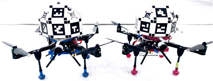
FIGURE 1. Developed drone-configuration for pose estimation evaluation.
In this work, we assume the existence of multiple UAV agents, each bearing an imaging modality without zooming capabilities, while their cameras are assumed to be mounted at the front of the vehicle. Having already introduced several methods for pose detection in Section 1, this research work focuses and extends the use of the ArUco fiducial markers framework (Romero-Ramirez et al., 2018). The identification process consists of a filtering process with local adaptive thresholding for edge extraction. This is followed by a contour extraction and a polygonal approximation to identify the rectangular markers. Then a size based elimination and marker code extraction is carried out, to be followed by marker identification and marker pose estimation. When applied to visual object pose tracking, assuming object distances of less or equal to 5m, this framework can provide a robust and accurate result of position and orientation (Xavier et al., 2017).
Each UAV is carries the fiducial marker arrangement similar to the one in Tsoukalas et al. (2018). This so called RhombicubOctahedron (RhOct) arrangement is comprised of squares and isosceles triangles as its facets and has an overall weight of 75g. The utilization of this Archimedean-solid, depicted in Figure 2 (left), allows for concurrent observation of these fiducial markers, as shown in Figure 2 (right).
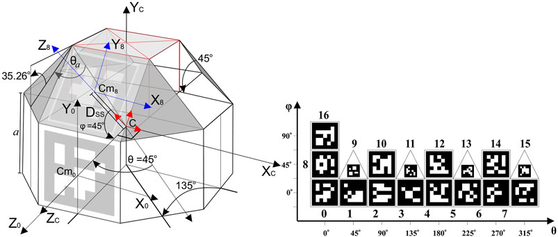
FIGURE 2. Truncated rhombicuboctahedron geometry and fiducial marker arrangement.
The truncated RhOct comprises of 13 squares and 4 triangle facets and has an area of
This configuration is expected to improve the pose estimation accuracy when more than one marker is detected. Additionally, it ensures robustness in occlusion and lighting conditions, as the system can identify the pose given only a subset of the markers. Such scenarios are depicted in Figure 3. In Figure 3C, the RhOct is partially occluded from the view, however its upper markers are still detected, allowing for the pose estimation process to conclude. Similarly, in Figure 3D two frames are shown with significant varying lighting conditions compared, and yet the RhOct’s pose can be extracted.
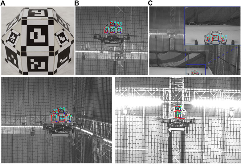
FIGURE 3. RhOct configuration (A), Detected marker (B), Occlusion case (C) and detection under various lighting conditions (D).
The algorithm for pose estimation is initialized by generating each fixed marker’s configuration on the RhOct. The marker identifying number and its corner geometry on the solid are obtained from a configuration file. The marker’s corner geometry, in this case refers, to the coordinates of its four corners with respect to the axis system Xc, Yc, Zc of Figure 2. Subsequently the online pose extraction is carried out for every new image acquisition using the following steps: 1) Detect fiducial (ArUco) markers in the image, 2) For each marker discovered extract the pixel coordinates of each corner, 3) Feed all pixel coordinates to a Perspective N–point solver of OpenCV library (Bradski, 2000) for extracting the RhOct’s pose with respect to the camera axis system. The algorithm encountered in the EPnP-formulation (Lepetit et al., 2009) was used to solve Perspective N-points (PnP) problem (Quan and Lan, 1999), due to its recursive nature which starts from the previously encountered solution. This algorithm is a significant enhancement to (Tsoukalas et al., 2018), where the center of the solid was extracted from each individual marker and then averaged, leading to ambiguity in individual marker pose extraction (Oberkampf et al., 1996). To address this, the algorithm simultaneously passes all marker corners (in pixels) to the solvePnP function, which in turn calculates the global optimal pose satisfying the initial fixed geometry of the RhOct.
Additional improvements include changes in the marker arrangement for more accuracy and improved detection frequency using a Region-of-Interest (RoI) approach. The adopted dictionary was “ARUCO_MIP_16h3” since this provides 4 × 4 markers which are easier to detect at larger distance than the default ArUco 6 × 6 ones. The markers at the square (triangular) facets were set to 48.75 (22.5)mm to accommodate space for the detection method. This method improved the accuracy, reduced jittering due to the sub-pixel corner refinement.
The adopted recursive RoI implementation assumes that a pose solution from the previous iteration exists, and the subsequent image is only cropped at a 1280 × 720 size around the center pixel of that solution and then passed to the pose detection algorithm. This implementation can handle 30 FpS in an i7-CPU implementation and the resulting algorithm is summarized in Figure 4.
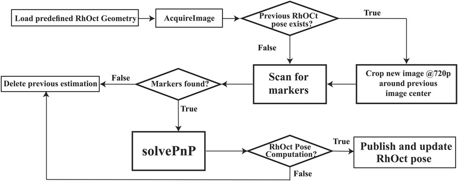
FIGURE 4. Flowchart of RhOct pose estimation algorithm.
3 Linearized UAV-Dynamics
Owing to inherent delays in the relative pose computation of the leader demands the inference of the maximum allowable lag, so that proper control parameters can be applied to the follower in order to efficiently maintain the leader within its Field-of-View (FoV).
The dynamic model of a quadrotor with mass m forms a set of nonlinear ODEs Sabatino, 2015. Let
Let the gyroscopic moments and any ground effect phenomena be absent, then the dynamic model of the quadrotor can be described as in
Linearizing around a hovering condition
These equations can be written in a compact form where the notation IN (0N) refers to an identity (zero) N × N matrix.
4 Controller Design and Maximum Allowable Delay for Leader/Follower UAV-Formation
The controllers for the altitude and attitude, as shown in Figure 5 within the Ardupilot framework are adopted in this study. For the z-axis a P-differentiator converts vertical position error to vertical velocity; this is subsequently converted to desired vertical acceleration through a cascade P-controller and finally through a PID-controller to motor output. For the xy-plane control a gain differentiator coverts the x and y position error to reference velocity, followed by a velocity PID which converts the velocity error to roll (pitch) when x (y) is referred. Correspondingly this amounts to a = ϕ (θ) when
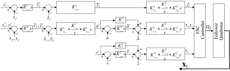
FIGURE 5. Ardupilot-based controller design for single UAV.
The four inputs ft, τx, τy and τz are then used in Eq. 1 to compute the Ωi, i = 1, … , 4 which are provided in the ESCs to power up the brushless motors of the quadrotor.
The resulting closed loop stable system takes the torm
where the subscript “f” indicates the follower quadrotor.
In a leader/follower configuration the deployment strategy and, thus, reference paths dynamically change upon changes to the position of the leader. Having obtain a dynamic model for a single drone, namely the follower’s dynamic behaviour, the potential coupling between a dynamically moving leader and the follower’s reference path strategy allows for the generation of a single linear model for the multi-agent UAV configuration, that is used for assessing the system stability. It should be noticed that for a single leader/follower UAV configuration this coupling is not necessary.
In a leader/follower configuration we use the subsript “l” to distinguish the leader from the follower quadrotor. The leader quadrotor performs a motion while the follower attempts to follow the leader’s motion at a certain distance in each axis, or xl−xf = cx, yl−yf = cy and zl−zf = cz where cx, cy and cz are constants and
In this work the use of an imaging modality for computing the relative pose between the leader and follower, means that the information does not need to be communicated between agents. Still, the refresh rate for the controller output cannot exceed the refresh rate of the imaging modality. In our case this is 30Hz, however for high resolution cameras of 12 mega-pixel it can be as low as 5Hz, which might affect tracking performance in the case of aggressive attitude motions from a leader. This scenario is of similar nature with communicating GPS sensed positioning between agents in outdoor environments for relative positioning. Since these sensors are bounded to a 4Hz frequency, the position of a leader will be communicated to a follower at 250msec for processing the calculations. Coupled to the data RF-transmission delay this interval can easily increase up to 350msec (excluding any lost packets). The follower will then need to compute
Hence there is an inherent varying delay in the feedback path since the vector
The follower quadrotor’s time-delayed dynamics is expressed as
This system is asymptotically stable for any constant delay h: 0 < h < hmax of there exist matrices p > 0, Q > 0 and Z > 0 such that (Gouaisbaut and Peaucelle, 2006; Xu and Lam, 2008)
An exhaustive search is needed to compute the maximum delay that is allowed under the time-delayed leader/follower configuration. It should be noted: 1) that the provided results are sufficient and higher values of hmax can still provide a stable system, and 2) the provided analysis is valid for near hovering conditions by the follower forcing a smooth trajectory [s(ϕ) ≃ ϕ and s(θ) ≃θ, or ϕ, θ ≤ 10°]. Furthermore the inherent assumption is that the leader remains within the FoV of the follower’s camera and the marker can be viewed with clarity.
5 Experimental Studies
In the following experimental study, the efficiency and accuracy of the suggested scheme is evaluated using two identical drones in a leader/follower formation.
5.1 Experimental Setup
The utilized quadrotors bear an imaging modality and a unique RhOct arrangement described in Section 2. Moreover, an Intel NUC i7 onboard computer and a PixHawk flight controller with the open-source ArduPilot (ArduPilot, 2021) framework are fitted for processing power and carrying out the low level flight actions respectively. The total weight of each UAV is 2.2kg with an allowable flight time of 11min using a 4-Cell LiPo battery. A FLIR BlackFlyS camera is used for image acquisition with a 2048 × 1534pixel resolution; the achievable acquisition rate using the onboard computer reached 37 FpS. The camera was calibrated using the ArUco calibration board for a fixed focus at 2.75m distance. 8-bit grayscale images were acquired to conform with the ArUco framework image processing methods, while the shutter speed was kept at 5nsec for minimizing blurriness. The utilized algorithms rely on the ROS (Quigley et al., 2009) framework and can be accessed from the following Github repository. A rendered version and the actual prototype are depicted in Figure 6 respectively. A motion capture system, comprising of 24 high resolution VICON cameras (Vicon motion systems, 2021) operating at 120 Hz was utilized for validating drones’ pose with 0.5mm and 0.5° accuracy.
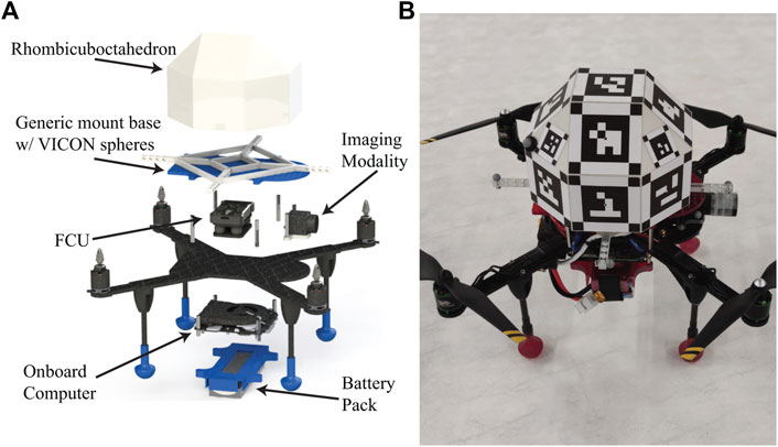
FIGURE 6. Developed UAV-rendering (A) and physical prototype (B).
5.2 Relative Pose Measurement With Stationary UAVs
This section investigates the maximum allowable detection distance for the RhOct configuration and the relative pose error as a function of the leader/follower distance. Both stationary UAVs were set so as to increase the distance between them |xl−xf| ∈ {1, 1.25, … , 4}m. At each distance we perform pose estimation of the leader’s RhOct, using the follower’s imaging modality for a duration of 120s. In Figure 7 the average and peak values of the pose estimation errors are depicted.
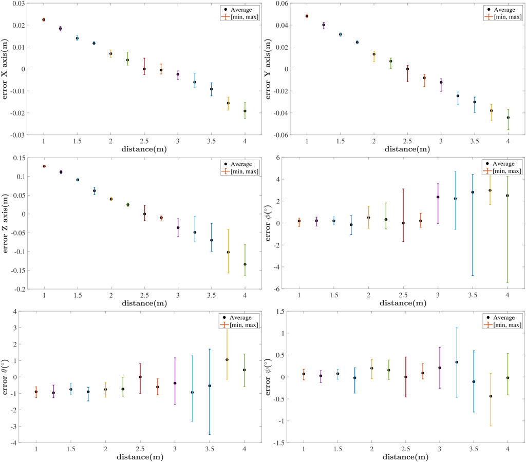
FIGURE 7. Attainable pose measurement error for stationary UAVs at different distances
All translational and rotational errors seem to drift away as the distance varies away from the optimal focal length distance of 2.75m. The algorithm operates extremely well at distances up to 4 m with a typical translational (rotational) error (3 × 4 × 15)cm (3° × 0.5° × 0.1°).
5.3 Relative Pose Measurement With Hovering UAVs
In order to account for the induced UAV-vibrations in measuring their pose, two drones in a hovering condition facing each other are used in this study. The relative error measured by our visual algorithm compared to the one inferred by the motion capture system is shown in Figure 8, where it is shown that the mean (worst) translational error was 4.9 × 13.8 × 73.9mm (11.5 × 113.8 × 203.7mm) for the XYZ axes respectively. These small errors are mainly attributed to the ArUco corner refinement algorithm and are consistent with the large deviations reported in the Z-axis (Ortiz-Fernandez et al., 2021).
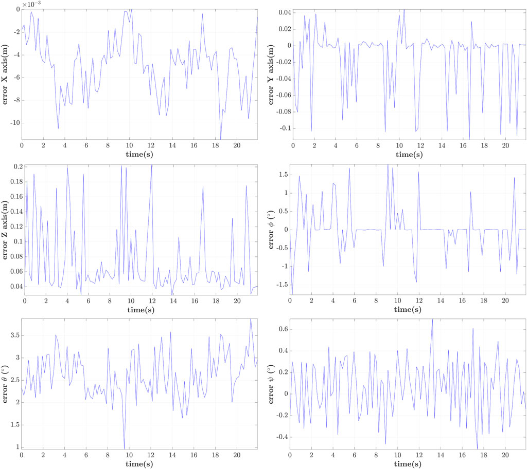
FIGURE 8. Visual vs. Motion Capture System induced pose measurement error.
For comparison purposes the relative position relying on raw GPS measurements for two stationary drones is shown in Figure 9. Thee drones are placed at 2.75m relative distance and their GPS receivers recorded their translational coordinates for 160s from six available satellites. The typical error was two orders of magnitude larger compared to the one from the visual system and is in agreement with the one reported in the literature; the rotational error from these measurements was constrained to 5° × 5° × 6°.
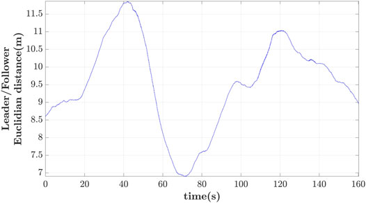
FIGURE 9. GPS-altitude relative error for stationary UAVs.
5.4 Leader-Follower Scenario Evaluation
In this scenario the leader is commanded to execute two consecutive skewed rectangular paths with predetermined waypoints, while these two rectangles are distanced from each other at 1m. The follower tracks the leader at a distance with parameters (cx, cy, cz) = (0, 2, 0)m using the controller from Eq. 9. The relative leader/follower distance is estimated through the leader’s detected RhOct. When the leader cannot be detected (i.e., being outside of the follower’s FoV or due to occlusion from obstacles) the follower remains in a hovering mode till the subsequent’s leader’s detection. The theoretical maximum allowable latency hmax was 1.9s and for emulation purposes such a delay is induced into calculating the follower’s reference altitude. Similarly to the previous cases, the positions of the two UAVs are compared using the VICON system for delays of 0.25, 1 and 1.25s.
In Figures 10–12 the 3D-path of the leader and follower is shown in the top-left portion, while their X, Y and Z trajectories are shown in the top-right, bottom-left and bottom-right parts respectively. These are expressed in the ENU frame configuration (X-forward, and Z-upward). For delays of h = 0.25s, shown in Figure 10, the follower closely follows the path of the leader with minimal lag. The leader completes its trajectory at 125s with a small translational velocity, so that it remains as much as possible within the follower’s FoV.
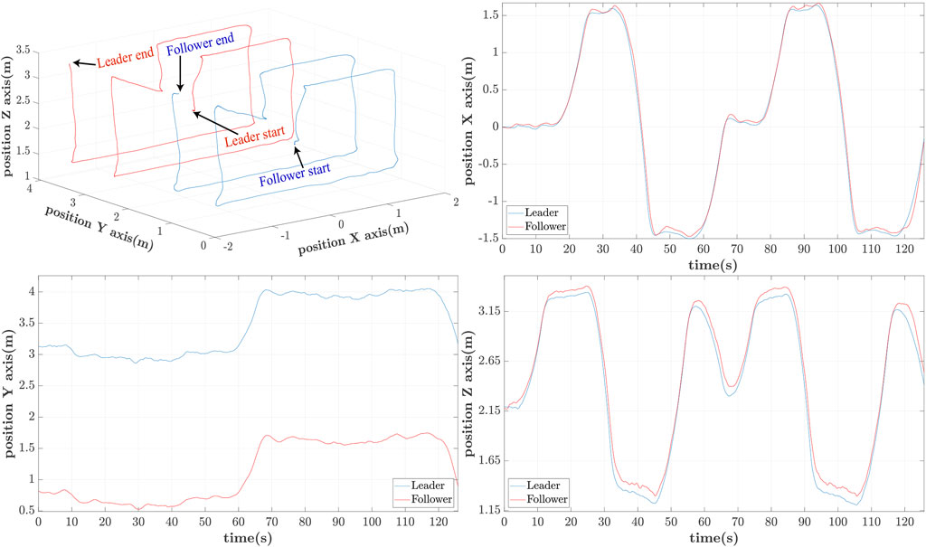
FIGURE 10. 3D Leader/Follower trajectories with h = 0.25s delay.
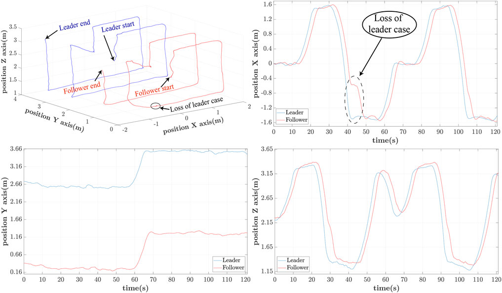
FIGURE 11. 3D Leader/Follower trajectories with h = 1s delay.
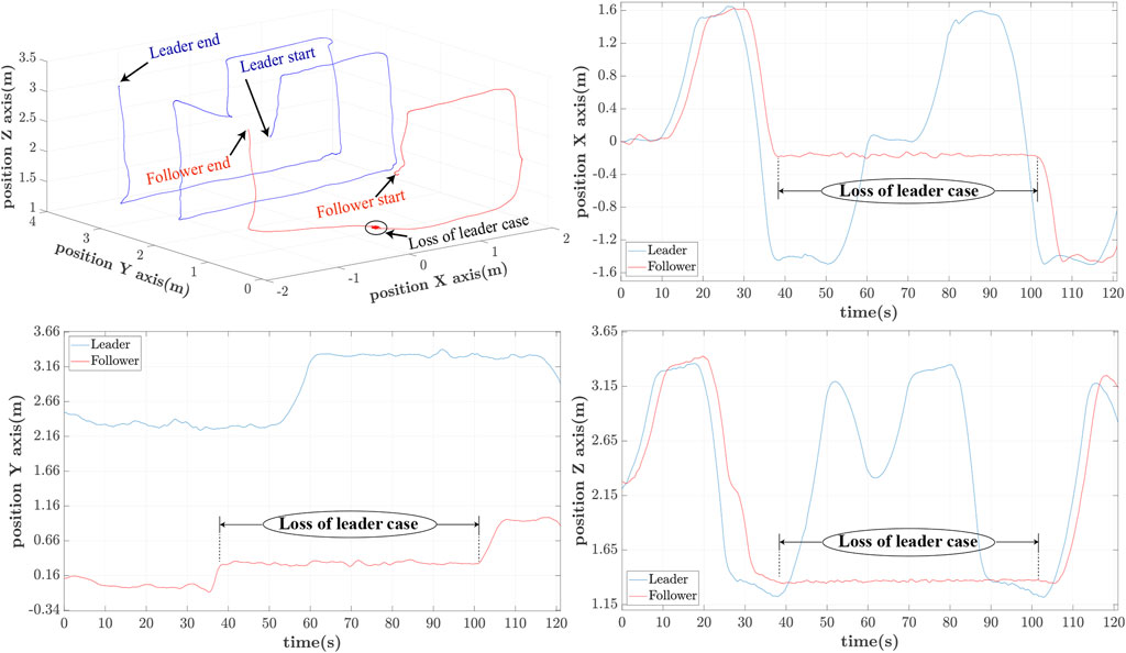
FIGURE 12. 3D Leader/Follower trajectories with h = 1.25s delay.
Similarly for h = 1s the path patterns are shown in Figure 11. Again we notice that the follower can accurately follow the path of the leader with an approximate phase lag of 2s. This delay is attributed to the UAV’s controller and the imposed h = 1s delay of applying the estimated reference path. It is also worth noticing a partial loss of the leader at 42s for a brief period of 3s due to the leader’s disappearance out of the follower’s-camera FoV.
The last iteration of h = 1.25s delay is included to showcase the behaviour of the leader/follower configuration upon loss of leader’s reference path. This is happening owing to the large delay, which leads to the leader’s moving out of the follower’s FoV. In this case, the follower switches to a hovering case per the adopted strategy, only to re-initiate the controller when the leader reappears within FoV at t ≃101s. This case appears in Figure 12, whereas the moments of losing and regaining view of the leader’s RhOct are visualized in Figure 13.
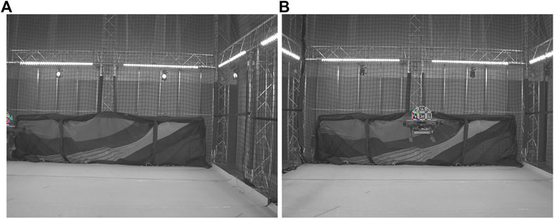
FIGURE 13. Follower’s camera FoV upon loss (A) and reappearance (B) of leader.
The relative Euclidean distance errors between the follower’s reference and actual position are depicted in Figure 14 for different delays. It should be noticed that the error is still computed when the leader is not within the FoV of the follower. As expected, there is significant drift of the follower’s reference path as the delay increases. The mean value of the error is: 1) 0.33m for 0.25s delay, 2) 0.41m for 1s, and 3) 0.81m for 1.25s delay. The loss of the leader is highlighted with the dashed line-segment of the error for the case of 1 and 1.25s delay.
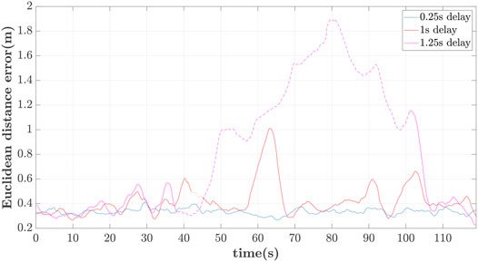
FIGURE 14. Follower’s Euclidean distance error vs. delay.
5.5 Extension to a Multiple-Agent Scenario
The aforementioned scheme can be extended to multi-agent relative localization in a swarm deployment experimentation. Such a case is shown in Figure 15, where three heterogeneous UAVs “1 thru 3” are fitted with a RhOct shown in the top-left portion while the pose detection algorithm is extended to multiple agents within the FoV of each drone. In this experiment drone 1 can view 2 and 3 (top-right), drone 2 can view 1 and partially 3 (bottom-left) while drone three can only observe 1 (bottom-right). A directed observation visual observation graph can be generated in this case having selected one of these as the anchor of the graph, In a leader/several followers scenario in this case, drone “1” is the leader being observable by both “2” and “3”. The only limiting factor in this case is the number of available dictionary of markers, where with a 4 × 4 fiducial dictionary, 1,000 markers can be generated which can be mounted in
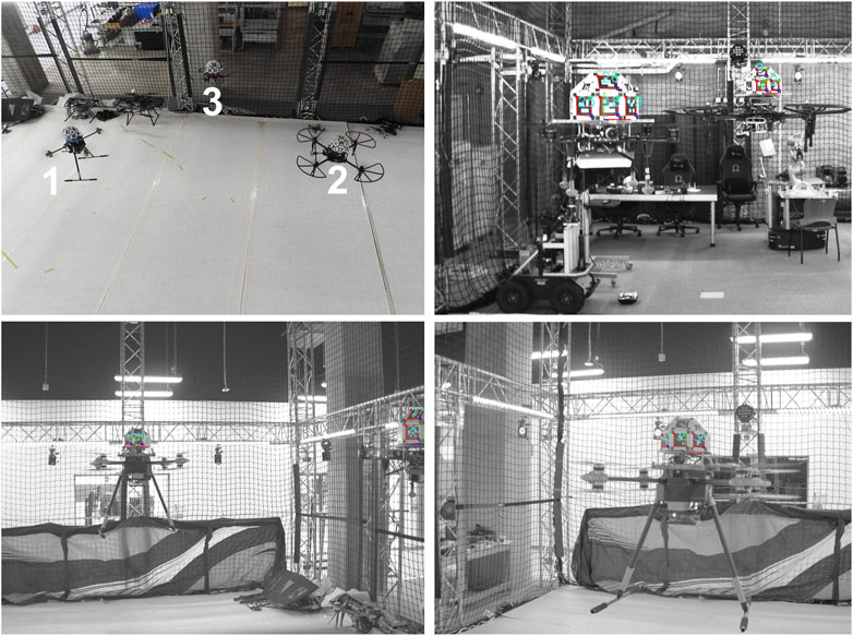
FIGURE 15. Swarm flying formation and detection view per agent.
6 Conclusions
In experimental leader/follower UAV-configurations, there is need to transmit the relative pose between these UAVs. Rather than relying on the individual FCUs and an RF-transmission scheme, fiducial markers are attached in each UAV. Using an onboard camera, these markers are accurately detected and the relative pose can be inferred within 30msec, as long as the leader is within the follower’s FoV and at a distance up to 4m. The maximum theoretical latency time is compared to the experimental one, while the FoV can be extended: 1) to cover the complete space if spherical cameras are used (Holter et al., 2021), and 2) focus in multiple agents.
Data Availability Statement
The raw data supporting the conclusion of this article will be made available by the authors, without undue reservation.
Author Contributions
Conceptualisation, NE, ATs, and ATz; Methodology, NE, ATs, and ATz; Software, NE and ATs; Hardware, NE, DC, and ATs; Validation, NE; Formal analysis, NE and ATz; Investigation, NE and ATz; Resources, NE, DC, ATs, and ATz; Experimentation, NE; Data curation, NE; Writing—original draft preparation, NE and ATz; Writing—review and editing, NE, ATs and ATz; Visualisations, NE; Supervision, ATz; Project administration, ATz; Funding acquisition, ATz. All authors have read and agreed to the published version of the manuscript.
Conflict of Interest
The authors declare that the research was conducted in the absence of any commercial or financial relationships that could be construed as a potential conflict of interest.
Publisher’s Note
All claims expressed in this article are solely those of the authors and do not necessarily represent those of their affiliated organizations, or those of the publisher, the editors and the reviewers. Any product that may be evaluated in this article, or claim that may be made by its manufacturer, is not guaranteed or endorsed by the publisher.
Acknowledgments
This work was partially performed at the KINESIS CTP facility, New York University Abu Dhabi, Abu Dhabi, 129188, United Arab Emirates.
Supplementary Material
The Supplementary Material for this article can be found online at: https://www.frontiersin.org/articles/10.3389/frobt.2021.777535/full#supplementary-material
Abbreviations
ENU, East-North-Up; FoV, Field-Of-View; FCU, Flight Control Unit; GNSS, Global Navigation Satellite System; GPS, Global Positioning System; NWU, North-West-Up; PnP, Perspective N-points; ROS, Robot Operating System; RTK, Real-time kinematic; SLAM, Simultaneous Localization and Mapping; UAV, Unmanned Aerial Vehicle; VOT, Visual Object Tracking.
References
Abeywardena, D. M. W., and Munasinghe, S. R. (2010). “Performance Analysis of a Kalman Filter Based Attitude Estimator for a Quad Rotor UAV,” in International Congress on Ultra Modern Telecommunications and Control Systems, Moscow, Russia, 18-20 Oct. 2010, 466–471. doi:10.1109/ICUMT.2010.5676596
ArduPilot (2021). ArduPilot Documentation. Available at: https://ardupilot.org/ardupilot/index.htm (Accessed on August 20, 2021).
Bircher, A., Alexis, K., Burri, M., Oettershagen, P., Omari, S., Mantel, T., et al. (2015). “Structural Inspection Path Planning via Iterative Viewpoint Resampling with Application to Aerial Robotics,” in 2015 IEEE International Conference on Robotics and Automation (ICRA), 26-30 May, Seattle, WA, USA, 6423–6430. doi:10.1109/ICRA.2015.7140101
Bisio, I., Garibotto, C., Haleem, H., Lavagetto, F., and Sciarrone, A. (2021). “On the Localization of Wireless Targets: A Drone Surveillance Perspective. IEEE Network 35, 249–255. doi:10.1109/MNET.011.2000648
Chen, Y., Tang, J., Jiang, C., Zhu, L., Lehtomäki, M., Kaartinen, H., et al. (2018). The Accuracy Comparison of Three Simultaneous Localization and Mapping (SLAM)-Based Indoor Mapping Technologies. Sensors 18, 3228. doi:10.3390/s18103228
Chuang, H.-M., He, D., and Namiki, A. (2019). Autonomous Target Tracking of UAV Using High-Speed Visual Feedback. Appl. Sci. 9, 4552. doi:10.3390/app9214552
Cossette, C. C., Shalaby, M., Saussie, D., Forbes, J. R., and Le Ny, J. (2021). Relative Position Estimation between Two UWB Devices with IMUs. IEEE Robot. Autom. Lett. 6, 4313–4320. doi:10.1109/LRA.2021.3067640
Dang, T., Mascarich, F., Khattak, S., Papachristos, C., and Alexis, K. (2019). “Graph-based Path Planning for Autonomous Robotic Exploration in Subterranean Environments,” in 2019 IEEE/RSJ International Conference on Intelligent Robots and Systems (IROS), 3-8 November, Macau, China, 3105–3112. doi:10.1109/IROS40897.2019.8968151
Daniele, M., and Emanuele, Z. (2021). Virtual Simulation Benchmark for the Evaluation of SLAM and 3d Reconstruction Algorithms Uncertainty. Meas. Sci. Technol. 32. doi:10.1088/1361-6501/abeccc
Das, A. K., Fierro, R., Kumar, V., Ostrowski, J. P., Spletzer, J., and Taylor, C. J. (2002). A Vision-Based Formation Control Framework. IEEE Trans. Robot. Automat. 18, 813–825. doi:10.1109/tra.2002.803463
Dufek, J., and Murphy, R. (2019). Visual Pose Estimation of Rescue Unmanned Surface Vehicle from Unmanned Aerial System. Front. Robot. AI 6, 42. doi:10.3389/frobt.2019.00042
Gassner, M., Cieslewski, T., and Scaramuzza, D. (2017). “Dynamic Collaboration without Communication: Vision-Based cable-suspended Load Transport with Two Quadrotors,” in 2017 IEEE International Conference on Robotics and Automation (ICRA), 29 May–3 June, Singapore, 5196–5202. doi:10.1109/ICRA.2017.7989609
Gkountas, K., and Tzes, A. (2021). Leader/Follower Force Control of Aerial Manipulators. IEEE Access 9, 17584–17595. doi:10.1109/ACCESS.2021.3053654
Gouaisbaut, F., and Peaucelle, D. (2006). Delay-dependent Robust Stability of Time Delay Systems. IFAC Proc. 39, 453–458. doi:10.3182/20060705-3-fr-2907.00078
Holter, S., Tsoukalas, A., Evangeliou, N., Giakoumidis, N., and Tzes, A. (2021). “Relative Spherical-Visual Localization for Cooperative Unmanned Aerial Systems,” in 2021 International Conference on Unmanned Aircraft Systems (ICUAS), 15-18 June, Athens, Greece, 371–376. doi:10.1109/icuas51884.2021.9476734
Kumar, G., Patil, A., Patil, R., Park, S., and Chai, Y. (2017). A LiDAR and IMU Integrated Indoor Navigation System for UAVs and its Application in Real-Time Pipeline Classification. Sensors 17, 1268. doi:10.3390/s17061268
LaValle, S., Yershova, A., Katsev, M., and Antonov, M. (2014). “Head Tracking for the Oculus Rift,” in 2014 IEEE International Conference on Robotics and Automation (ICRA), 31 May–7 June, Hong Kong, China, 187–194. doi:10.1109/icra.2014.6906608
Lepetit, V., Moreno-Noguer, F., and Fua, P. (2009). EPnP: An Accurate O(n) Solution to the PnP Problem. Int. J. Comput. Vis. 81, 155–166. doi:10.1007/s11263-008-0152-6
Li, G., Ge, R., and Loianno, G. (2021). Cooperative Transportation of Cable Suspended Payloads with MAVs Using Monocular Vision and Inertial Sensing. IEEE Robot. Autom. Lett. 6, 5316–5323. doi:10.1109/LRA.2021.3065286
Long Quan, L., and Zhongdan Lan, Z. (1999). Linear N-point Camera Pose Determination. IEEE Trans. Pattern Anal. Machine Intell. 21, 774–780. doi:10.1109/34.784291
López-Cerón, A., and Canas, J. M. (2016). “Accuracy Analysis of Marker-Based 3d Visual Localization,” in XXXVII Jornadas de Automatica Workshop, 7-9 September, Madrid, Spain, 8.
Lu, Y., Xue, Z., Xia, G.-S., and Zhang, L. (2018). A Survey on Vision-Based UAV Navigation. Geo-spatial Inf. Sci. 21, 21–32. doi:10.1080/10095020.2017.1420509
Mahendran, S., Ali, H., and Vidal, R. (2017). “3D Pose Regression Using Convolutional Neural Networks,” in 2017 IEEE Conference on Computer Vision and Pattern Recognition Workshops (CVPRW), 21-26 July, Honolulu, HI, USA, 494–495. doi:10.1109/CVPRW.2017.73
Mariottini, G. L., Pappas, G., Prattichizzo, D., and Daniilidis, K. (2005). “Vision-based Localization of Leader-Follower Formations,” in Proceedings of the 44th IEEE Conference on Decision and Control (IEEE), 15 December, Seville, Spain, 635–640.
McConville, A., Bose, L., Clarke, R., Mayol-Cuevas, W., Chen, J., Greatwood, C., et al. (2020). Visual Odometry Using Pixel Processor Arrays for Unmanned Aerial Systems in GPS Denied Environments. Front. Robot. AI 7, 126. doi:10.3389/frobt.2020.00126
Mondragon, I. F., Campoy, P., Martínez, C., and Olivares-Méndez, M. A. (2010). “3D Pose Estimation Based on Planar Object Tracking for UAVs Control,” in 2010 IEEE International Conference on Robotics and Automation, 35–41. doi:10.1109/ROBOT.2010.5509287
Mur-Artal, R., Montiel, J. M. M., and Tardos, J. D. (2015). ORB-SLAM: a Versatile and Accurate Monocular SLAM System. IEEE Trans. Robot. 31, 1147–1163. doi:10.1109/tro.2015.2463671
Mur-Artal, R., and Tardos, J. D. (2017). ORB-SLAM2: An Open-Source Slam System for Monocular, Stereo, and RGB-D Cameras. IEEE Trans. Robot. 33, 1255–1262. doi:10.1109/tro.2017.2705103
Nguyen, H., and Alexis, K. (2021). Forceful Aerial Manipulation Based on an Aerial Robotic Chain: Hybrid Modeling and Control. IEEE Robot. Autom. Lett. 6, 3711–3719. doi:10.1109/LRA.2021.3064254
Oberkampf, D., DeMenthon, D. F., and Davis, L. S. (1996). Iterative Pose Estimation Using Coplanar Feature Points. Computer Vis. Image Understanding 63, 495–511. doi:10.1006/cviu.1996.0037
Ortiz-Fernandez, L. E., Cabrera-Avila, E. V., Silva, B. M. F. d., and Gonçalves, L. M. G. (2021). Smart Artificial Markers for Accurate Visual Mapping and Localization. Sensors 21, 625. doi:10.3390/s21020625
Papachristos, C., Alexis, K., Carrillo, L. R. G., and Tzes, A. (2016). “Distributed Infrastructure Inspection Path Planning for Aerial Robotics Subject to Time Constraints,” in 2016 International Conference on Unmanned Aircraft Systems (ICUAS), 7-10 June, Arlington, VA, USA, 406–412. doi:10.1109/ICUAS.2016.7502523
Papachristos, C., Kamel, M., Popović, M., Khattak, S., Bircher, A., Oleynikova, H., et al. (2019a). Autonomous Exploration and Inspection Path Planning for Aerial Robots Using the Robot Operating System, 3. Berlin: Springer International Publishing, 67–111. chap. Robot Operating System (ROS): The Complete Reference. doi:10.1007/978-3-319-91590-6_3
Papachristos, C., Khattak, S., Mascarich, F., Dang, T., and Alexis, K. (2019b). “Autonomous Aerial Robotic Exploration of Subterranean Environments Relying on Morphology-Aware Path Planning,” in 2019 International Conference on Unmanned Aircraft Systems (ICUAS), 11-14 June, Atlanta, GA, USA, 299–305. doi:10.1109/ICUAS.2019.8797885
Patel, N., Krishnamurthy, P., Tzes, A., and Khorrami, F. (2021). “Overriding Learning-Based Perception Systems for Control of Autonomous Unmanned Aerial Vehicles,” in 2021 International Conference on Unmanned Aircraft Systems (ICUAS) (IEEE), 15-18 June, Athens, Greece, 258–264. doi:10.1109/icuas51884.2021.9476881
Qingbo, G., Nan, L., and Baokui, L. (2012). “The Application of GPS/SINS Integration Based on Kalman Filter,” in Proceedings of the 31st Chinese Control Conference, 25-27 July, Hefei, China, 4607–4610.
Quigley, M., Ken, C., Brian, G., Josh, F., Tully, F., Jeremy, L., et al. (2009). “ROS: an Open-Source Robot Operating System,” in ICRA Workshop on open source software, 12-17 May, Kobe, Japan 32, 5.
Radwan, N., Valada, A., and Burgard, W. (2018). VLocNet++: Deep Multitask Learning for Semantic Visual Localization and Odometry. IEEE Robot. Autom. Lett. 3, 4407–4414. doi:10.1109/LRA.2018.2869640
Romero-Ramirez, F. J., Muñoz-Salinas, R., and Medina-Carnicer, R. (2018). Speeded up Detection of Squared Fiducial Markers. Image Vis. Comput. 76, 38–47. doi:10.1016/j.imavis.2018.05.004
Sabatino, F. (2015). “Quadrotor Control: Modeling, Nonlinearcontrol Design, and Simulation,” (Stockholm, Sweden: KTH, Automatic Control). Master’s thesis.
Schmuck, P., and Chli, M. (2017). “Multi-UAV Collaborative Monocular SLAM,” in 2017 IEEE International Conference on Robotics and Automation (ICRA), 29 May–3 June, Singapore, 3863–3870. doi:10.1109/ICRA.2017.7989445
Shin, J.-M., Kim, Y.-S., Ban, T.-W., Choi, S., Kang, K.-M., and Ryu, J.-Y. (2020). Position Tracking Techniques Using Multiple Receivers for Anti-drone Systems. Sensors 21, 35. doi:10.3390/s21010035
Shule, W., Almansa, C. M., Queralta, J. P., Zou, Z., and Westerlund, T. (2020). UWB-based Localization for Multi-UAV Systems and Collaborative Heterogeneous Multi-Robot Systems. Proced. Comput. Sci. 175, 357–364. The 17th International Conference on Mobile Systems and Pervasive Computing (MobiSPC),The 15th International Conference on Future Networks and Communications (FNC),The 10th International Conference on Sustainable Energy Information Technology. doi:10.1016/j.procs.2020.07.051
Smolyanskiy, N., and Gonzalez-Franco, M. (2017). Stereoscopic First Person View System for Drone Navigation. Front. Robot. AI 4, 11. doi:10.3389/frobt.2017.00011
Steich, K., Kamel, M., Beardsley, P., Obrist, M. K., Siegwart, R., and Lachat, T. (2016). “Tree Cavity Inspection Using Aerial Robots,” in 2016 IEEE/RSJ International Conference on Intelligent Robots and Systems (IROS), 9-14 October, Daejeon, Korea (South), 4856–4862. doi:10.1109/IROS.2016.7759713
Sun, Q., Xia, J., Foster, J., Falkmer, T., and Lee, H. (2017). Pursuing Precise Vehicle Movement Trajectory in Urban Residential Area Using Multi-Gnss Rtk Tracking. Transportation Res. Proced. 25, 2356–2372. doi:10.3390/s1906131210.1016/j.trpro.2017.05.255
Suwatthikul, C., Chantaweesomboon, W., Manatrinon, S., Athikulwongse, K., and Kaemarungsi, K. (2017). “Implication of Anchor Placement on Performance of Uwb Real-Time Locating System,” in 2017 8th International Conference of Information and Communication Technology for Embedded Systems (IC-ICTES), 7-9 May, Chonburi, Thailand, 1–6. doi:10.1109/ICTEmSys.2017.7958760
Trujillo, J.-C., Munguia, R., Urzua, S., Guerra, E., and Grau, A. (2020). Monocular Visual SLAM Based on a Cooperative UAV-Target System. Sensors 20, 3531. doi:10.3390/s20123531
Tsiourva, M., and Papachristos, C. (2020). “LiDAR Imaging-Based Attentive Perception,” in 2020 International Conference on Unmanned Aircraft Systems (ICUAS), 1-4 September, Athens, Greece, 622–626. doi:10.1109/ICUAS48674.2020.9213910
Tsoukalas, A., Tzes, A., and Khorrami, F. (2018). “Relative Pose Estimation of Unmanned Aerial Systems,” in 2018 26th Mediterranean Conference on Control and Automation (MED), 19-22 June, Zadar, Croatia, 155–160. doi:10.1109/MED.2018.8442959
Tsoukalas, A., Tzes, A., Papatheodorou, S., and Khorrami, F. (2020). “UAV-deployment for City-wide Area Coverage and Computation of Optimal Response Trajectories,” in 2020 International Conference on Unmanned Aircraft Systems (ICUAS), 1-4 September, Athens, Greece, 66–71. doi:10.1109/ICUAS48674.2020.9213831
Tsoukalas, A., Xing, D., Evangeliou, N., Giakoumidis, N., and Tzes, A. (2021). “Deep Learning Assisted Visual Tracking of Evader-UAV,” in 2021 International Conference on Unmanned Aircraft Systems (ICUAS), 15-18 June, Athens, Greece, 252–257. doi:10.1109/ICUAS51884.2021.9476720
Upadhyay, J., Rawat, A., and Deb, D. (2021). Multiple Drone Navigation and Formation Using Selective Target Tracking-Based Computer Vision. Electronics 10, 2125. doi:10.3390/electronics10172125
van Diggelen, F., and Enge, P. (2015). “The World’s First GPS MOOC and Worldwide Laboratory Using Smartphones,” in Proceedings of the 28th International Technical Meeting of the Satellite Division of The Institute of Navigation (ION GNSS+ 2015), 14-18 September, Tampa, FL, USA, 361–369.
Vicon motion systems (2021). Vicon X ILM: Breaking New Ground in a Galaxy Far, Far Away. Available at: https://www.vicon.com/ (Accessed on 21 August, 2021).
Wang, J., and Olson, E. (2016). “AprilTag 2: Efficient and Robust Fiducial Detection,” in 2016 IEEE/RSJ International Conference on Intelligent Robots and Systems (IROS) (IEEE), 9-14 October, Daejeon, Korea (South), 4193–4198. doi:10.1109/iros.2016.7759617
Wang, Z., Wang, B., Tang, C., and Xu, G. (2020). “Pose and Velocity Estimation Algorithm for UAV in Visual Landing,” in 2020 39th Chinese Control Conference (CCC), 27-29 July, Shenyang, China, 3713–3718. doi:10.23919/CCC50068.2020.9188491
Wittmann, F., Lambercy, O., and Gassert, R. (2019). Magnetometer-Based Drift Correction during Rest in IMU Arm Motion Tracking. Sensors 19, 1312. doi:10.3390/s19061312
Xavier, R. S., da Silva, B. M. F., and Goncalves, L. M. G. (2017). “Accuracy Analysis of Augmented Reality Markers for Visual Mapping and Localization,” in 2017 Workshop of Computer Vision (WVC), 30 October–1 November, Natal, Brazil, 73–77. doi:10.1109/WVC.2017.00020
Xu, H., Ding, Y., Li, P., Wang, R., and Li, Y. (2017). An RFID Indoor Positioning Algorithm Based on Bayesian Probability and K-Nearest Neighbor. Sensors 17, 1806. doi:10.3390/s17081806
Xu, S., and Lam, J. (2008). A Survey of Linear Matrix Inequality Techniques in Stability Analysis of Delay Systems. Int. J. Syst. Sci. 39, 1095–1113. doi:10.1080/00207720802300370
Yang, J.-C., Lin, C.-J., You, B.-Y., Yan, Y.-L., and Cheng, T.-H. (2021). RTLIO: Real-Time LiDAR-Inertial Odometry and Mapping for UAVs. Sensors 21, 3955. doi:10.3390/s21123955
Yokoyama, R. S., Kimura, B. Y. L., and dos Santos Moreira, E. (2014). An Architecture for Secure Positioning in a UAV Swarm Using RSSI-Based Distance Estimation. SIGAPP Appl. Comput. Rev. 14, 36–44. doi:10.1145/2656864.2656867
Keywords: UAV, drone, swarm, leader follower, relative localization
Citation: Evangeliou N, Chaikalis D, Tsoukalas A and Tzes A (2022) Visual Collaboration Leader-Follower UAV-Formation for Indoor Exploration. Front. Robot. AI 8:777535. doi: 10.3389/frobt.2021.777535
Received: 15 September 2021; Accepted: 18 November 2021;
Published: 04 January 2022.
Edited by:
Rodrigo S. Jamisola Jr, Botswana International University of Science and Technology, BotswanaReviewed by:
Daniel Villa, Federal University of Espirito Santo, BrazilAbdelkader Nasreddine Belkacem, United Arab Emirates University, United Arab Emirates
Copyright © 2022 Evangeliou, Chaikalis, Tsoukalas and Tzes. This is an open-access article distributed under the terms of the Creative Commons Attribution License (CC BY). The use, distribution or reproduction in other forums is permitted, provided the original author(s) and the copyright owner(s) are credited and that the original publication in this journal is cited, in accordance with accepted academic practice. No use, distribution or reproduction is permitted which does not comply with these terms.
*Correspondence: Nikolaos Evangeliou, bmlrb2xhb3MuZXZhbmdlbGlvdUBueXUuZWR1