
95% of researchers rate our articles as excellent or good
Learn more about the work of our research integrity team to safeguard the quality of each article we publish.
Find out more
METHODS article
Front. Robot. AI , 22 June 2021
Sec. Robotic Control Systems
Volume 8 - 2021 | https://doi.org/10.3389/frobt.2021.663809
This article provides a theory for provably safe and computationally efficient distributed constrained control, and describes an application to a swarm of nano-quadrotors with limited on-board hardware and subject to multiple state and input constraints. We provide a formal extension of the explicit reference governor framework to address the case of distributed systems. The efficacy, robustness, and scalability of the proposed theory is demonstrated by an extensive experimental validation campaign and a comparative simulation study on single and multiple nano-quadrotors. The control strategy is implemented in real-time on-board palm-sized unmanned erial vehicles, and achieves safe swarm coordination without relying on any offline trajectory computations.
Swarms of aerial robots or Unmanned Aerial Vehicles (UAVs) are emerging as a disruptive technology that enables highly re-configurable, on-demand, distributed intelligent autonomous systems with high impact on many areas of science, technology, and society (Chung et al., 2018).
These swarms can be employed to solve real-world tasks where the environment is to be explored (Marconi et al., 2012; Bayram et al., 2017), and to be traversed or exploited (Vásárhelyi et al., 2018) with a prescribed goal state or a desired formation. To operate effectively in uncertain real-world environments, each agent in the swarm must be capable of safely navigating to its target along a-priori unknown paths. Not only does each robot need to respect its operational constraints (e.g. actuator saturation, speed limits, allowed flight zones), it must also avoid collisions with environmental hazards and other agents (Franchi et al., 2012; Alonso-Mora et al., 2015; Franchi et al., 2016; Zhou et al., 2018) in the presence of imperfect dynamic models, measurement noise, and communication delays. Most importantly, to ensure a high level of safety and robustness, the robots should use their on-board computational resources rather than relying on off-board resources (e.g. a ground control station). The latter provide a central point of failure, and are susceptible to time delays, communication overhead, and information loss. This calls for reactive and distributed control algorithms that can be implemented in real-time on-board UAVs and only rely on local information to solve the global navigation task safely.
Achieving goal satisfaction and safety certificates for a swarm of autonomous Micro Aerial Vehicles (MAVs) presenting limited resources for on-board computation, power, communication, sensing, and actuation is considerably challenging (Chung et al., 2018). Moreover, even for large platforms with more advanced capabilities, the computational power available to implement control algorithms is typically limited in favor of running mission-dependent algorithms related to localization and sensing systems (Brockers et al., 2014). Hence, computationally efficient and provably safe on-board algorithms for multi-robot systems are of paramount importance for achieving safety-critical tasks in complex environments.
In this work, we develop a provably safe and robust constrained control methodology that is fully distributed and can be implemented on the individual agents of a swarm of Vertical Take-Off and Landing (VTOL) vehicles. The algorithm is validated using the smallest open-source available nano-quadrotor platform, i.e. Bitcraze’s Crazyflie 2.1. An accompanying video can be found at https://youtu.be/le6WSeyTXNU.
As discussed in (Murray, 2007; Brambilla et al., 2013; Parker et al., 2016; Chamanbaz et al., 2017; Chung et al., 2018; Coppola et al., 2020), swarm robotics has become an active area of research covering a broad spectrum of topics within the robotics and control communities. The problem of safely controlling the motion of aerial robot swarms can be classified based on approaches for which the main portion of the algorithm, and especially the part that ensures safety and goal satisfaction, is running either off-board or on-board the UAVs. This classification is motivated because most existing works provide algorithmic contributions which belong to the off-board category (see Section 2.1), but as explained in Section 1, on-board navigation algorithms (see Section 2.2) are preferred from a safety and autonomy perspective.
Unfortunately, there does not exist one safe navigation strategy that suits all UAV applications. For each strategy there is an inherent trade-off between computational efficiency, performance, safety guarantees, simplicity, generality, and scalability to swarms. To provide a fair point of comparison, it is worth noting that VTOLs can vary significantly in terms of the available on-board computational power. For instance, a 35 g Crazyflie quadrotor carries an STM32F4 microprocessor with a clock speed of 168MHz and 192kB RAM. For comparison, larger platforms with a mass above ±700 g can use processors like the Odroid-XU4 (Liu et al., 2018) or the NVIDIA TX2 (Jung et al., 2018; Sanket et al., 2018; Ding et al., 2019; Carrio et al., 2020). The latter has a six-core CPU, each with a clock speed of 2GHz, a 256-core NVIDIA GPU, and 8 GB RAM. Since very limited battery power for computation, memory, and communication available to tiny MAVs intrinsically calls for different kinds of navigation and control strategies (Purohit et al., 2014), the literature review is mainly limited to off-board and on-board navigation strategies applied to nano-quadrotors.
Most approaches, such as (Campos-Macías et al., 2017; Chen et al., 2017; Herbert et al., 2017; Preiss et al., 2017a; Wang et al., 2017; Fridovich-Keil et al., 2018; Honig et al., 2018; Kolaric et al., 2018; Cappo et al., 2018a; Cappo et al., 2018b; Xu and Sreenath, 2018; Bajcsy et al., 2019; Du et al., 2019; Fathian et al., 2019; Liu et al., 2019; Luis and Schoellig, 2019; Rubies-Royo et al., 2019; Vukosavljev et al., 2019), try to ensure a particular level of safety and robustness, by running the core search-based or optimization-based algorithms off-board the UAVs, and thus outsource the high computational cost to ground control stations that send the trajectories to the UAV’s on-board position or attitude controller. Frameworks such as (Preiss et al., 2017a; Honig et al., 2018) combine graph-based planning and continuous trajectory optimization to compute safe and smooth trajectories, but take several minutes for a swarm of hundreds of quadrotors in obstacle-rich environments. In (Luis and Schoellig, 2019), a scalable distributed model predictive control algorithm with on-demand collision avoidance is proposed to perform point-to-point transitions with labeled agents. This strategy reduces the computation time to the order of seconds. (Campos-Macías et al., 2017) introduces a hybrid approach to trajectory planning, fusing sampling-based planning techniques and model-based optimization via quadratic programming (QP). For a single nano-quadrotor in obstacle-dense environments, a provably safe trajectory can be computed online every 0.1–1s, depending on the scenario. Frameworks such as (Du et al., 2019; Vukosavljev et al., 2019) are based on designing off-board libraries of safe motion primitives for a swarm of tiny MAVs, but typically require too much memory for on-board implementation. (Du et al., 2019) relies on combinatorial and nonlinear optimization techniques that are executed on a central computer, requires iterative procedures to resolve collisions between agents in a sequential manner, and does not guarantee to find a feasible solution. A modular, robust, and hierarchical framework for safe planning of robot teams is proposed in (Vukosavljev et al., 2019). Although the run-time components, executed off-board, require only a small computing time, this approach is centralized, requires a-priori known environments and is conservative due to the restriction to a discretization, i.e. a gridded workspace partitioned into rectangular boxes. Works based on the online FaSTrack motion planner (Herbert et al., 2017) provide strong safety guarantees under the assumption of a single near-hover quadrotor with a decoupled structure (Fridovich-Keil et al., 2018) or obtain weaker safety guarantees using neural network classifiers to consider control-affine dynamics (Rubies-Royo et al., 2019). Hamilton-Jacobi reachability analysis was applied to multi-agent swarms using sequential priority ordering (Bajcsy et al., 2019) or the selection of air highways (Chen et al., 2017). A centralized multi-robot system planner for enabling theatrical performance is designed in (Cappo et al., 2018a; Cappo et al., 2018b) using time-aware trajectory formulation for validation, verification, and trajectory refinement. The human intent is translated online into non-colliding and dynamically feasible trajectories for multiple nano-quadrotors. Safety barrier certificates based on exponential control barrier functions are used in (Wang et al., 2017) to ensure in a minimally invasive way collision-free maneuvers for teams of small quadrotors flying through formations and in (Xu and Sreenath, 2018) for the safe teleoperation of nano-quadrotor swarms via a remote joystick in a set of static constraints. In (Wang et al., 2017) this requires a centralized QP to be solved at 50 Hz on a ground PC to minimize the difference between the actual and nominal control. Distributed formation control approaches that have been demonstrated on small quadrotors, but are computed off-board have shown robustness to bounded measurement noise (Kolaric et al., 2018), to communication delays, nonlinearities, parametric perturbations, and external disturbances (Liu et al., 2019). Input feasibility and collision avoidance is guaranteed in (Fathian et al., 2019) for single-integrator dynamics, and is claimed to be extendable to agents with higher-order dynamics in (Fathian et al., 2018).
Only few works such as (Preiss et al., 2017b; Desaraju and Michael, 2018; McGuire et al., 2019) achieved to run computationally efficient navigation algorithms on-board the small embedded flight controllers of nano-quadrotors, but mostly with limited safety guarantees. These strategies typically can only handle first order dynamics, can only deal with a small set of constraints and a small number of agents, or require too much on-board memory. In (McGuire et al., 2019), a swarm gradient bug algorithm reacts to static obstacles on the fly, but collisions still occur. In (Preiss et al., 2017b), single piece polynomial planners can follow predefined paths uploaded offline for a single quadrotor, but are not suitable for dynamically changing environments. They use artificial potential fields on a swarm of these UAVs hovering in formation and show avoidance of an obstacle with a known position in a distributed fashion, but without providing theoretical safety certificates on collision avoidance or actuator saturation. A promising approach to the computationally efficient robust constrained control of nonlinear systems is proposed in (Desaraju et al., 2018) and uses an experience driven Explicit MPC (EMPC). This method was implemented in (Desaraju and Michael, 2018) and reliably ran at 100 Hz on board the tiny MAV’s firmware in the presence of control input and velocity constraints. Due to the nature of EMPC, however, the introduction of collision avoidance constraints between multiple robots would make the EMPC database grow exponentially in size, thus becoming prohibitive for fast online queries.
To the best of our knowledge, the literature does not provide any provably safe control techniques that achieve on-board real-time control of large nano-quadrotor swarms with higher-order dynamics in the presence of actuator, obstacle, and agent collision avoidance constraints.
This work is based on the Explicit Reference Governor (ERG), which is a novel framework for the closed-form feedback control of nonlinear systems subject to constraints on the state and input variables (Nicotra and Garone, 2018). This approach does not rely on online optimization and is particularly promising for control applications with fast dynamics, limited on-board computational capabilities, or strict regulations on code reliability. This article extends the centralized ERG framework (Nicotra and Garone, 2018) and a distributed ERG (D-ERG) (Nicotra et al., 2015) formulation, and encapsulates these two core contributions:
1. The ERG theory is extended to distributed multi-agent systems with fourth-order dynamics and subject to constraints on states and actuator inputs. This work supplies all theoretical details of a general and scalable D-ERG framework along with a formal proof on correctness, the formulation of different offline design strategies for computing safe threshold values of Lyapunov and invariance-based level sets. Moreover we formulated two swarm collision avoidance control policies, a decentralized and a distributed version, that require a different information exchange.
2. The effectiveness, robustness, and computational efficiency of our control and navigation layers, running on-board the Crazyflie nano-quadrotor at 500 Hz, is validated extensively in several scenarios with single or multiple quadrotors subject to state and input constraints. All proposed formulations are validated and quantitatively compared. These are the first published experimental results on the use of ERG and D-ERG on quadrotors, and (to the best of our knowledge) is the only work in the literature that achieves provably safe constrained control at such high frequencies on-board nano-quadrotors for such a broad set of state and input constraints. The D-ERG’s goal satisfaction and safety certificates are put in sharp contrast with those of a Navigation Field method that suffers from instabilities and collisions when the agents posses higher-order dynamics.
The rest of this article is organized as follows. Section 3 introduces the used notation. The problem is formulated in Section 4. The proposed strategy is outlined in Section 5, and constitutes the control layer and the navigation layer which are described in Section 6 and in Section 7, respectively. The results of extensive hardware validations and a comparative simulation study with single and swarms of nano-quadrotors are presented in Section 8, and discussed in Section 9. Finally, some concluding remarks are given in Section 10.
In this work, all vectors are column vectors. Unit vectors are denoted using the hat symbol
whereas the vee operator
The system and parts of the problem are stated first. Section 4.1 presents the dynamic model of a generic quadrotor. Nevertheless, the proposed method can be readily extended to any VTOL vehicle. The state and input constraints, which each agent should always satisfy, are defined in Section 4.2 and illustrated in this video https://youtu.be/le6WSeyTXNU.
As depicted in Figure 1, each agent of the robotic swarm is modeled as a quadrotor with mass
As detailed in (Hua et al., 2013), the dynamic model of a generic VTOL subject to a gravitational force in the
where
subject to the control input vector
For the specific case of a quadrotor, it is possible to rewrite the control input (5) as a function of the motor voltage commands
where d is the nominal distance between the motor axis and the center of mass of the aircraft, and
To ensure safety of a swarm of
Actuator saturation has been observed as the primary cause of instability for quadrotors in free flight. Indeed, whenever one of the motors is subject to saturation, the control law is unable to generate an arbitrary torque vector. This can lead to undesired attitude oscillations that quickly devolve into catastrophic failures. To prevent this scenario, each motor voltage
with
All agents have collision radius
with
In addition to planar walls, all agents must also avoid collision with
with cylinder radius
To prevent undesirable interactions between agents (e.g. collision, propeller downwash, sonar jamming), each pair of agents is tasked with satisfying the following dynamic cylindrical exclusion constraints
As per the previous case, it is trivial to replace the cylindrical constraint with a spherical constraint if vertical agent interactions are not deemed problematic.
The aim of this paper is to develop a guaranteed safe distributed constrained control strategy for an homogeneous swarm of quadrotors with very limited on-board resources for computation, memory, and communication. It is assumed that all agents are collaborative and that the locations of all nearby obstacles are known within the MAV’s limited sensing range. Let each agent be subject to an a priori unknown and arbitrary reference
The purpose of this paper is to design a feedback control law in the form
• Safety: For any piecewise continuous reference
• Asymptotic Stability: If the reference
• Robustness: The control law must ensure safety and stability in the presence of model uncertainty, sensor noise, and external disturbances;
• Reactiveness: The control law must run in real-time on-board the nano-quadrotor’s hardware, without relying on off-board pre-generated trajectories;
• Scalability: Each agent must be capable of generating its own control input based on local information. To this end, inter-agent communication is limited to a given radius.
The main challenge that arises from the control problem stated in Section 4.3 is that it combines the nonlinear dynamics of the individual agent with the nonconvex constraints of the aggregated swarm. The higher-order nonlinear agent dynamics (3) would be significantly easier to stabilize in the absence of constraints, whereas the position constraints (8)–(10) would be easier to enforce if the agent dynamics were a first-order linear system
The first task, which is handled by the Control Layer, consists in pre-stabilizing the dynamics of each agent to a locally defined reference
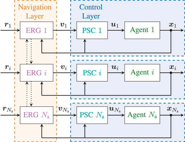
FIGURE 2. Distributed Constrained Control Architecture
The goal of the control layer is to pre-stabilize the individual quadrotors using a classical nonlinear inner-outer loop control law (Mellinger and Kumar, 2011; Hua et al., 2013). This is done without accounting for the state or input constraints, which will instead be handled by the navigation layer. The proposed architecture of the control layer is illustrated in Figure 3.
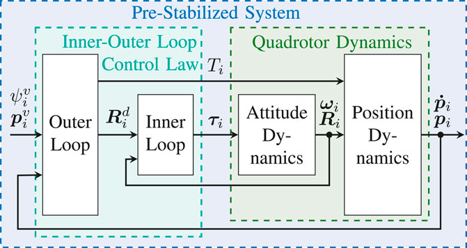
FIGURE 3. Pre-Stabilizing Control Scheme
The objective of the outer loop is to control the position of the quadrotor under the assumption that the attitude dynamics are instantaneous. To this end, we define the auxiliary control input
where
where
The target attitude is
The objective of the inner loop is to control the attitude dynamics of the UAV such that the rotation matrix
and compute the control torques as follows,
where
The following Lemma states the robustness of the outer loop dynamics to attitude errors.
Lemma 1. Let system (3) be subject to the outer loop controller (12), with
with
is a Lyapunov function of the outer loop dynamics
Proof: Given
where
with
Noting that
The ERG is a general framework for the constrained control of nonlinear systems introduced in (Garone and Nicotra, 2016; Nicotra and Garone, 2018). Consider a pre-stabilized system
the transient dynamics of the closed-loop system cannot cause a constraint violation;
However, rather than pre-computing a suitable trajectory
where
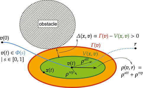
FIGURE 4. Basic Idea of the Invariant Level Set Explicit Reference Governor
This section extends the ERG framework to handle the case of multi-agent systems. The main challenge is given by the fact that the Distributed ERG (D-ERG) solution must ensure the satisfaction of multi-agent coordination constraints
Here, the objective is to show that it is possible to ensure convergence and constraint satisfaction for the overall swarm by manipulating the reference of each agent in a distributed fashion as follows
with
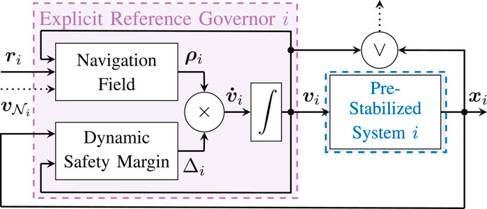
FIGURE 5. Distributed Explicit Reference Governor (D-ERG) Scheme for Agent i. To ensure that the constraints are satisfied for any desired reference configuration
DEFINITION 1 (Navigation Field). Let the NF
satisfies the following.
1.
2.
3.
4. For any constant reference
The key takeaway from Definition 1 is that it only considers the first-order dynamics (22). Thus, the NF is only responsible for generating a steady-state admissible path that connects the current references
DEFINITION 2 (Dynamic Safety Margin). Let the DSM
satisfies the following.
1.
2.
3.
4.
5.
6.
The intuition behind the DSM is that it quantifies the distance between the constraints and the transient dynamics of the individual closed-loop system.
Theorem 1. Consider N identical pre-stabilized systems
Given the navigation field
•
•
for any piecewise continuous reference
Moreover, given a constant aggregate reference
•
as long as
Proof: As detailed in the proof of (Nicotra and Garone, 2018), Theorem 1, it can be shown that (21) ensures
It is worth noting that, if
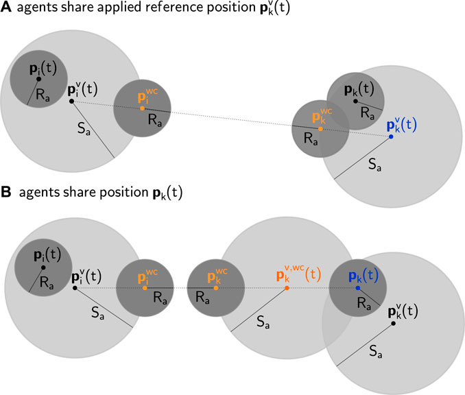
FIGURE 6. Geometric 2D representation of distributed collision avoidance between two pre-stabilized agents i(left) and k(right) with safety radii

TABLE 1. Computational Requirements of the D-ERG Algorithm
As detailed in (Nicotra and Garone, 2018), the NF of agent i can be designed using a traditional attraction and repulsion field1
where the attraction field is
The repulsion field is the sum of linear repulsion fields pushing away from walls (w), obstacles (o), and nearby agents (a), i.e.
The repulsion field of all wall constraints is
where
with an influence margin
where
with circulation gain
In a similar way, one can define the repulsion field that acts on agent i caused by the other agents k as
where
with
with
Following from Theorem 1, (24), agent collision can now be avoided by introducing the auxiliary constraint
As shown in Figure 6, the combination of (37) and (38) satisfies (10).
Remark 1. Equations (35) and (36) assume that agent i knows the difference between its own reference and the reference of agent k. However, the contribution of agent k becomes zero if
where the latter has the advantage of not requiring inter-agent communication but also leads to a more conservative coordination strategy, as illustrated in Figure 6.
For each agent i its DSM, used in (21), can be obtained by taking the worst case DSM (i.e. the smallest one) of all active saturation (s), wall (w), obstacle (o), and agent collision (a) constraints2,
For the offline design of the DSM we do not rely on explicit trajectory predictions, but use Lyapunov theory and optimization to design the DSM. As such, the following lemma is an important result used throughout this work to compute offline safe threshold values of Lyapunov level sets. As was visualized in Figure 4, it guarantees constraint satisfaction if the system dynamics never make its Lyapunov level set value
Lemma 2. Given a nonlinear pre-stabilized system
be a Lyapunov function and let
be a linear constraint. Then, the Lyapunov treshold value
is such that
Proof: See (Nicotra et al., 2019).▪
Since the DSM is computed on a per-agent basis, the agent index i will be omitted for the sake of notational simplicity. The following paragraphs address each constraint separately.
In this section we show three strategies to compute a safe threshold value that ensure constraints on at least a subset of the inputs (5) are satisfied. The quantitative effects of these three strategies for an input constrained double integrator system are depicted in Figure 7.
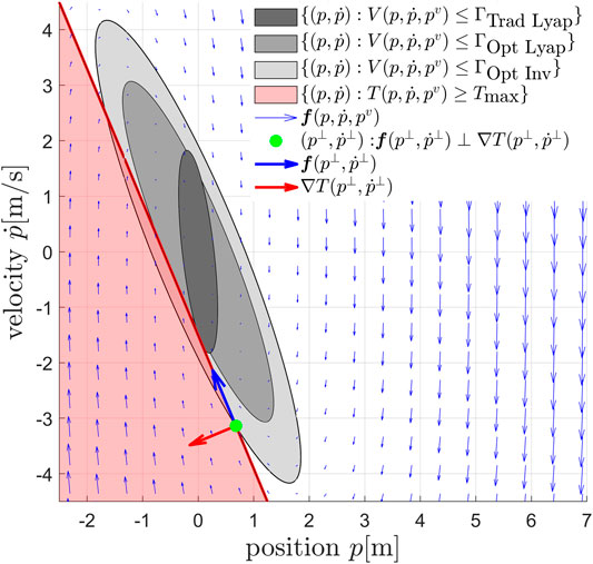
FIGURE 7. Phase plane representation of the proposed input constraint enforcement strategies, illustrated for a second-order dynamical system
Traditional Lyapunov Level Set Strategy (Trad Lyap): One practical approach is to consider the outer loop control law and ensure the box constraints on the total thrust are satisfied,
Since the inequality constraint (43) is nonlinear in the outer loop state variables, it is necessary to find a linear constraint that implies (43), in order to apply Lemma 2. A possible approach to provide a linear constraint is to make a distinction between the steady-state thrust
it is therefore sufficient to ensure that,
This is equivalent to limiting the maximum acceleration of the UAV in any direction. The main interest with (45) is that it defines a rotationally invariant constraint that is linear for any given unitary vector
Similarly,
with
Optimally Aligned Lyapunov Level Set Strategy (Opt Lyap): This section is an extension of the theory in (Garone et al., 2018) and applies it to higher-order quadrotor dynamics. Since linear systems are characterized by an infinite choice of quadratic Lyapunov functions, a way to improve the performance of the outer loop dynamics is to select the optimal Lyapunov based threshold value that is perfectly aligned with the total thrust constraints, instead of using (46), which is not aligned. Hence, one can find a common Lyapunov function in the quadratic form
with
the optimal Lyapunov function can be obtained by solving the following linear matrix inequality
where
Given the quadratic Lyapunov function (48), we obtain the threshold values
The DSM that prevents the total thrust to saturate and is based on the Lyapunov function that is optimally aligned with this constraint, then becomes
Optimally Aligned Invariant Level Set Strategy (Opt Inv): A more generic safe set can be obtained by considering the outer loop dynamics (19) with input (12) and computing offline the threshold value associated to the largest possible optimally aligned Lyapunov level set that satisfies the constraints of the following minimization problem
with the closed position loop dynamics
Remark 2. To avoid motor saturation when tracking a non-zero yaw reference, it is also necessary to add an ERG on the yaw axis. This can be done using the NF in (26) and the DSM
with
The convex inequality constraints (8) are equivalent to (41) with
The dynamic safety margin corresponding to the wall constraint closest to violation then becomes,
with
Constraint (9) defines a non-convex admissible region. Given a fixed reference
As a result, (9) can be enforced by simply ensuring
The inequality constraints define a reference-dependent virtual wall and are equivalent to (41) with
with
As explained in Section 7.2, collision avoidance can be satisfied by also enforcing the auxiliary constraint (38). Since constraint (38) applies equally in every direction in 3D space, it can be enforced using the Lyapunov threshold value associated to the linear constraint
thus leading to
The DSM related to this constraint then becomes,
with
We present the first results of an extensive experimental validation of the ERG and the D-ERG frameworks by means of single and multi-robot hardware experiments (a video of the experiments can be found at https://youtu.be/le6WSeyTXNU) using the experimental setup described hereafter. In a comparative simulation campaign we have analyzed statistically the goal and constraint satisfaction properties of our methodology. A summary of these results can be found in Section 9.
The experiments are performed using Crazyflie 2.1 nano-quadrotors in a Vicon motion capture system for indoor localization based on the Crazyswarm system architecture of (Preiss et al., 2017b). The computationally efficient control and navigation layers of Sections 6 and 7 are implemented in C and run at
Each UAV is modeled with a static safety radius of
Here, we list guidelines for the tuning of the main parameters of the control and navigation layer and how this relates to the obtained performance and robustness. We advise users of this approach to tune the parameters in the order as they are listed below and to start with the input saturation constraints, followed by static and dynamic obstacle constraints.
First tune the inner loop gains KR, Kω > 0 and then the outer loop gains KP, KD > 0 for stable regulation control performance. The outer loop's settling time should be an order of magnitude slower than the one of the inner loop. This step is accomplished without worrying about the effect on any of the input or state constraints. The stiffer the pre-stabilized closed-loop system is tuned, the more the agents can be stacked in a smaller volume, at the cost of a more precise and higher rate odometry.
Eliminate numerical noise in the attraction field by selecting a strictly positive, but small value for the smoothing radius η.
Increase the DSM gains κ until no further performance increase is obtained. These gains are chosen such that the DSMs of the active constraints have the same order of magnitude.
Choose medium influence margins ζ defining from how far the obstacles are considered in the repulsion field. Too large values will require too large sensing ranges for static obstacles or communication ranges for dynamic obstacles, whereas too low values do not give enough reaction time.
For cooperative agent collision avoidance, choose the maximum position error radius Sa. The larger this value, the higher the maximum attainable robot's speed, but the larger the distance traveled by each agent to reach its goal.
Select small circulation gains α around obstacles and agents to avoid robots getting stuck in local saddle points. Too large values tend to increase the settling time.
Choose strictly positive static safety margins δ to increase robustness. This also ensures the NF's repulsion term achieves its maximum amplitude while the DSM stays strictly positive. Hence this allows moving (and not blocking) the reference in directions pointing outward the obstacle constraint.
In all the experiments, the control gains of the inner-outer loop control law detailed in Section 6 are KP = 13.0 I3, KD = 5.0 I3, KR = diag(0.005, 0.005, 0.0003), and KΩ = diag(0.001, 0.001, 0.00005), which give moderately aggressive performance. The attraction field of the navigation layer is chosen with η = ηψ = 0.005. Other parameters defined in Section 7 are specified in the following sections.
In the accompanying video we show that point-to-point transitions can easily destabilize a pre-stabilized quadrotor due to actuator saturation when the changes in
The goal of the experiments is to validate the theory of Section 7.3.1 by showing that the navigation layer ensures safety for whatever
Trad Lyap: traditional Lyapunov-based DSM (47), with
Opt Lyap: optimally aligned Lyapunov-based DSM (53), with
Opt Inv: invariance-based DSM (55), with
As is depicted in Figure 8, in each of these experiments, the UAV starts from the initial hovering position
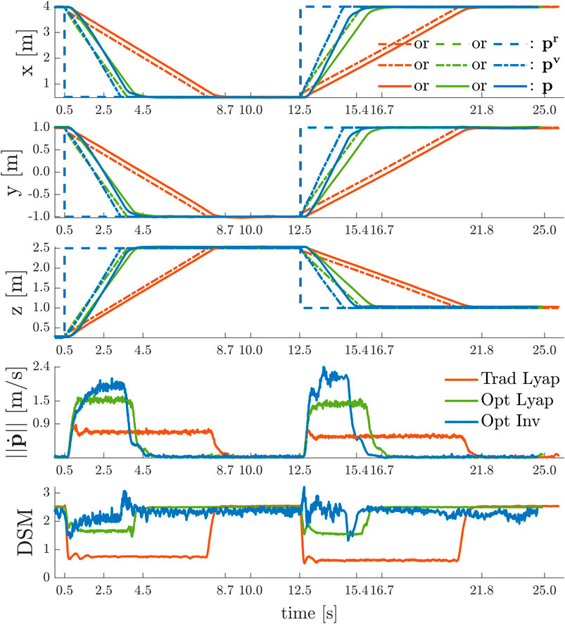
FIGURE 8. Point-to-Point Transitions Without Violation of Input Constraints
The desired position set-point is always reached in a stable and safe (i.e.
To show the effect of time-varying yaw angle references, we sequentially performed the following two experiments with the quadrotor using the invariance based ERG on the total thrust constraints and using either:
• no ERG on the yaw axis ψ;
• an ERG on yaw axis ψ as in (56) with
In each of these experiments, depicted in Figure 9, the UAV starts from the initial position
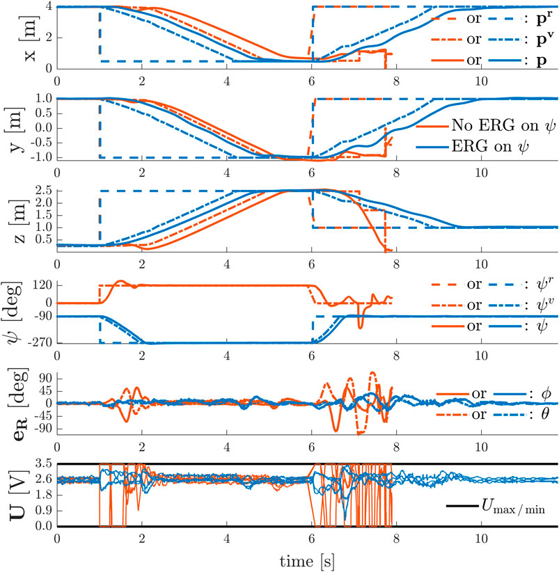
FIGURE 9. Simultaneous Point-to-Point Transitions and Discontinuous Yaw References With and Without Violation of Input Constraints
In the absence of an ERG on the yaw axis, the system remains stable under severe actuator saturation for the simultaneous position and yaw commands given at
The results depicted in Figure 10 show the aerial vehicle avoiding two virtual walls with
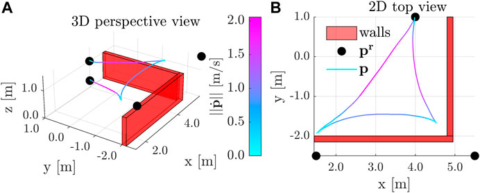
FIGURE 10. Point-to-Point Transitions with Wall Avoidance
In these experiments the UAVs are modeled as cylinders as detailed in Section 4.2.4, preventing them to fly over each other. Similarly to (Preiss et al., 2017a; Honig et al., 2018; Vukosavljev et al., 2019), this choice prevents a MAV’s propeller downwash effect to destabilize other MAVs which are flying closely underneath.
In this experiment we show that the D-ERG ensures a swarm of
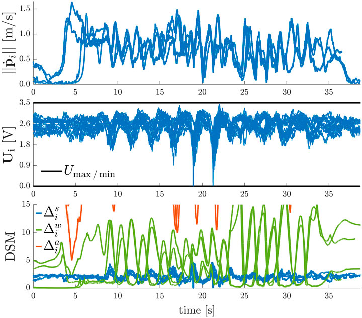
FIGURE 11. Results of the Human-Swarm Teleoperation Experiment in a Confined Environment
In Figure 12 the results of two experiments with a swarm of
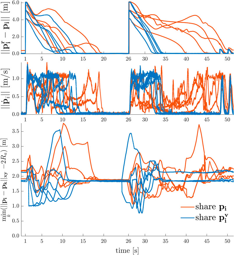
FIGURE 12. 2D Point-to-Point Transitions with Agent Collision and Deadlock Avoidance
Similar to the 2D line formation experiments, Figure 13 depicts the results of formation transitioning experiments in 3D with a swarm of
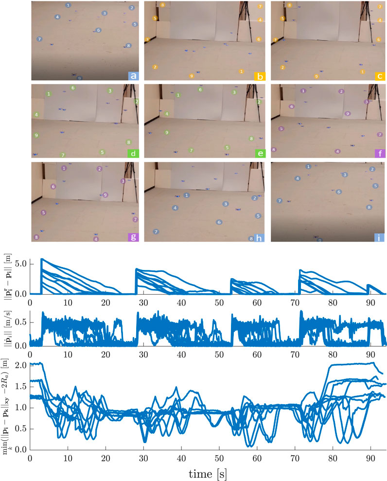
FIGURE 13. 3D Point-to-Point Transitions with Agent Collision Avoidance
In this simulation study we show some relevant statistics on the occurrence of constraint violations or deadlocks and compare the D-ERG with another optimization-free (i.e., closed form or explicit) approach solely based on attractive and repulsive Navigation Fields. The latter method is implemented by using the NF of Section 7.2 and by setting the DSM, which is a dynamic state-dependent and reference-dependent gain, to a user-tuned constant value. The latter can be interpreted as a fixed reference filter gain, which can only be selected before executing an experiment.
The results on safety and goal satisfaction for 3D point-to-point transitions of quadrotors in an increasingly densely filled environment with static obstacles and dynamic agents are depicted in Table 2. We use a cubic environment with side lengths of
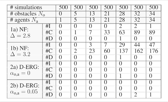
TABLE 2. Simulation Statistics on Safety and Goal Satisfaction
The strong safety certificates obtained when employing the D-ERG method are clear from the simulation data summarized in Table 2. The occurrence of instabilities and collisions is zero for the certified safe D-ERG, whereas for the Navigation Field (NF) method the occurrence is considerably large. When the constant reference gain in the NF approach is increased from
For what concerns the goal satisfaction certificates, we observe almost global asymptotic stability. The statistical occurrence of deadlocks is almost negligible and only becomes measurable for very densely filled environments cluttered with agents and obstacles. Although a non-zero circulation gain ensures that pairs of agents cannot get stuck in local-saddle points, one can see that there is little benefit in using a circulation gain with a large number of agents. For some simulations it helps to avoid a deadlock, whereas in other simulations it can cause agents to get stuck in a local minimum. However, it is worth noting that this limitation is a consequence of the proposed NF and is not inherent to the D-ERG framework.
In Section 8, we presented an extensive set of experimental and simulation studies of the proposed ERG and Distributed ERG framework, with the first real-world experiments to be found in the literature. These studies demonstrate the following key results (R) when applied to a homogeneous swarm of cooperative Crazyflie 2.1 quadrotors:
R1: Computational efficiency allows high-rate real-time (
R2: Almost globally asymptotically stable control performance for arbitrary position and yaw references (e.g. point-to point transitions or human-swarm teleoperation scenarios) for swarms in constrained environments. The measured statistical deadlock occurrence is negligible;
R3: Provable safety under actuator inputs and state constraints, including collision avoidance between dynamical agents, and between agents and static obstacles;
R4: Robustness in the presence of real-world uncertainties (e.g. non-modeled inner loop dynamics, variability of thrust and torque constants or battery voltages, battery displacement from center of mass, sensor noise, communication delays). The low-level control layer is proven to be robust to small attitude errors. Moreover, the D-ERG leverages the robustness of low-level controllers and maintains this property. Since the D-ERG’s DSMs itself relies on level-sets (i.e. Lyapunov or invariant set-based) and not on explicit state and input trajectory predictions to obtain safety guarantees, the overall approach is less model dependent and hence more robust;
R5: Planner or reference agnostic safety certification with the ability to handle steady-state inadmissible references;
R6: Offline ERG design strategies for the selection of safe threshold values to Lyapunov level-sets can lead to significant improvements in the control performance over traditional methods. Especially when the level sets are aligned with the constraints or when the more generic invariant safe sets are used with negligible increase of the on-board computational requirements.
R7: The local nature of the D-ERG makes the algorithm scale very well with the number of agents. The distributed formulation that relies on local inter-agent distance and direction in applied reference positions (i.e. requiring agent communication) can lead to significantly smaller settling times and a denser swarm when compared to the decentralized formulation relying on inter-agent distance and direction in positions (i.e. requiring communication or exteroceptive sensing).
Algorithm 1In future work, the proposed model-based add-on scheme can be further extended and combined with other control approaches, such as the adaptive control laws to deal with e.g. unmodeled dynamics, actuator deadzones as in (Wang et al., 2019; Yang et al., 2021a), and unavailable velocity measurements as in (Yang et al., 2021b) due to noisy low-cost sensors.In this article we formulated the theory of a provably safe distributed constrained control framework, i.e., the Distributed Explicit Reference Governor (D-ERG), and demonstrated its efficacy on a homogeneous swarm of collaborative nano-quadrotors (i.e., a swarm of palm-sized Crazyflies 2.1) through multiple hardware and simulation experiments.
This approach has the following merits. Safety is guaranteed for agents with higher-order dynamics and with a large set of hard constraints such as the four actuator input limits and static and dynamic collision avoidance constraints. In contrast to optimization-based control schemes, this algorithm has a low cost of computation and memory and runs in real-time at a 500 Hz rate on-board the limited available robot hardware. Thereby, its local and reactive nature provides a good scalability to a large number of robots and obstacles. Since this add-on scheme only requires a pre-stabilized plant, it can be of great practical use when the controller is not accessible or not allowed to be changed, which is very often the case for commercial UAV flight control units. Its simple yet effective design makes it an interesting method for industrial robotic applications requiring safe real-time control systems.
However, some limitations still exist and can be addressed in future work. Since the Dynamic Safety Margin uses a single scalar to change the amplitude of the applied reference signal in the direction of the Navigation Field, the performance would reduce when applying this technique to systems with an increased state space dimension. Also, this robust level-set based D-ERG approach comes at the cost of an increased level of conservatism compared to approaches where the future trajectory is explicitly predicted or optimized for. Although the statistical occurrence of deadlocks is very low, the employed Navigation Field does not formally guarantee the absence of deadlocks.
The raw data supporting the conclusion of this article will be made available by the authors, without undue reservation.
BC and MN contributed to the conception and formulation of the theory behind the D-ERG. BC was involved in designing and performing all the numerical simulations and hardware validations on the aerial robot swarm. KM assisted with the hardware validations and debugging the numerical simulations. BC wrote the first draft of the manuscript, all authors contributed to manuscript revision, read, and approved the submitted version.
This work was supported by the Research Foundation Flanders (FWO) under grant numbers 37472, 60523, and 62062, by the Flemish Government under the program “Onderzoeksprogramma Artificiële Intelligentie (AI) Vlaanderen”, and by the US government’s National Science Foundation award CMMI 1904441.
The authors declare that the research was conducted in the absence of any commercial or financial relationships that could be construed as a potential conflict of interest.
The authors would like to thank the Research and Engineering Center for Unmanned Vehicles (RECUV) of the University of Colorado Boulder for providing continued access to the motion capture system used for the experimental validation, even in the midst of moving to a new campus.
1dependency of
2dependency of
Alonso-Mora, J., Naegeli, T., Siegwart, R., and Beardsley, P. (2015). Collision Avoidance for Aerial Vehicles in Multi-Agent Scenarios. Autonomous Robots 39, 101–121. doi:10.1007/s10514-015-9429-0
Bajcsy, A., Herbert, S. L., Fridovich-Keil, D., Fisac, J. F., Deglurkar, S., Dragan, A. D., et al. (2019). A Scalable Framework for Real-Time Multi-Robot, Multi-Human Collision Avoidance. In International Conference on Robotics and Automation (IEEE), 936–943. doi:10.1109/ICRA.2019.8794457
Bayram, H., Stefas, N., Engin, K. S., and Isler, V. (2017). Tracking Wildlife with Multiple UAVs: System Design, Safety and Field Experiments. in Proceedings of the IEEE International Symposium on Multi-Robot and Multi-Agent Systems. Los Angeles, CA, December 4–5, 2017, 97–103. doi:10.1109/MRS.2017.8250937
Brambilla, M., Ferrante, E., Birattari, M., and Dorigo, M. (2013). Swarm Robotics: a Review from the Swarm Engineering Perspective. Swarm Intelligence 7, 1–41. doi:10.1007/s11721-012-0075-2
Brockers, R., Hummenberger, M., Weiss, S., and Matthies, L. (2014). Towards Autonomous Navigation of Miniature UAV. in Proceedings of the IEEE Computer Society Conference on Computer Vision and Pattern Recognition Workshops. Washington, DC: IEEE Computer Society, 645–651. doi:10.1109/CVPRW.2014.98
Campos-Macías, L., Gómez-Gutiérrez, D., Aldana-López, R., De La Guardia, R., and Parra-Vilchis, J. I. (2017). A Hybrid Method for Online Trajectory Planning of Mobile Robots in Cluttered Environments. IEEE Robotics Automation Lett. 2, 935–942. doi:10.1109/LRA.2017.2655145
Cappo, E. A., Desai, A., Collins, M., and Michael, N. (2018a). Online Planning for Human-Multi-Robot Interactive Theatrical Performance. Autonomous Robots 42, 1771–1786. doi:10.1007/s10514-018-9755-0
Cappo, E. A., Desai, A., and Michael, N. (2018b). Robust Coordinated Aerial Deployments for Theatrical Applications Given Online User Interaction via Behavior Composition. in Distributed Autonomous Robotic Systems. 6 edn. Cham, Switzerland: Springer, 665–678. doi:10.1007/978-3-319-73008-0_46
Carrio, A., Tordesillas, J., Vemprala, S., Saripalli, S., Campoy, P., and How, J. P. (2020). Onboard Detection and Localization of Drones Using Depth Maps. IEEE Access 8, 30480–30490. doi:10.1109/access.2020.2971938
Chamanbaz, M., Mateo, D., Zoss, B. M., Tokić, G., Wilhelm, E., Bouffanais, R., et al. (2017). Swarm-Enabling Technology for Multi-Robot Systems. Front. Robotics AI 4, 12. doi:10.3389/frobt.2017.00012
Chen, M., Hu, Q., Fisac, J. F., Akametalu, K., Mackin, C., and Tomlin, C. J. (2017). Reachability-based Safety and Goal Satisfaction of Unmanned Aerial Platoons on Air Highways. J. Guidance, Control Dyn. 40, 1360–1373. doi:10.2514/1.G000774
Chung, S.-J., Paranjape, A., Dames, P., Shen, S., and Kumar, V. (2018). A Survey on Aerial Swarm Robotics. IEEE Trans. Robotics 34, 837–855. doi:10.1109/TRO.2018.2857475
Coppola, M., McGuire, K. N., De Wagter, C., and de Croon, G. C. (2020). A Survey on Swarming With Micro Air Vehicles: Fundamental Challenges and Constraints. Front. Robotics AI 7, 18. doi:10.3389/frobt.2020.00018
Desaraju, V. R., and Michael, N. (2018). Efficient Prioritization in Explicit Adaptive NMPC through Reachable-Space Search. in AIAA Guidance, Navigation, and Control Conference, Kissimmee, FL, January 8–12, 2018, 1–19. doi:10.2514/6.2018-1847
Desaraju, V. R., Spitzer, A. E., O’Meadhra, C., Lieu, L., and Michael, N. (2018). Leveraging Experience for Robust, Adaptive Nonlinear MPC on Computationally Constrained Systems with Time-Varying State Uncertainty. Int. J. Robotics Res. 37, 1690–1712. doi:10.1177/0278364918793717
Ding, W., Gao, W., Wang, K., and Shen, S. (2019). An Efficient B-Spline-Based Kinodynamic Replanning Framework for Quadrotors. IEEE Trans. Robotics 35, 1287–1306. doi:10.1109/TRO.2019.2926390
Du, X., Luis, C. E., Vukosavljev, M., and Schoellig, A. P. (2019). Fast and in Sync: Periodic Swarm Patterns for Quadrotors. in Proceedings of the 2019 International Conference on Robotics and Automation (ICRA), Montreal, QC, Canada, May 20–24, 2019, 9143–9149. doi:10.1109/ICRA.2019.8794017
Fathian, K., Safaoui, S., Summers, T. H., and Gans, N. R. (2019). Robust 3D Distributed Formation Control with Collision Avoidance and Application to Multirotor Aerial Vehicles. in Proceedings of the 2019 International Conference on Robotics and Automation (ICRA), Montreal, QC, Canada, May 20–24, 2019, 9209–9215. doi:10.1109/ICRA.2019.8794349
Fathian, K., Summers, T. H., and Gans, N. R. (2018). Robust Distributed Formation Control of Agents with Higher-Order Dynamics. IEEE Control. Syst. Lett. 2, 495–500. doi:10.1109/LCSYS.2018.2841941
Franchi, A., Secchi, C., Son, H. I., Bülthoff, H. H., and Giordano, P. R. (2012). Bilateral Teleoperation of Groups of Mobile Robots with Time-Varying Topology. IEEE Trans. Robotics 28, 1019–1033. doi:10.1109/TRO.2012.2196304
Franchi, A., Stegagno, P., and Oriolo, G. (2016). Decentralized Multi-Robot Encirclement of a 3D Target with Guaranteed Collision Avoidance. Autonomous Robots 40, 245–265. doi:10.1007/s10514-015-9450-3
Fridovich-Keil, D., Herbert, S. L., Fisac, J. F., Deglurkar, S., and Tomlin, C. J. (2018). Planning, Fast and Slow: A Framework for Adaptive Real-Time Safe Trajectory Planning. IEEE Int. Conf. Robotics Automation, 387–394. doi:10.1109/ICRA.2018.8460863
Garone, E., and Nicotra, M. M. (2016). Explicit Reference Governor for Constrained Nonlinear Systems. IEEE Trans. Automatic Control. 61, 1379–1384. doi:10.1109/TAC.2015.2476195
Garone, E., Nicotra, M., and Ntogramatzidis, L. (2018). Explicit Reference Governor for Linear Systems. Int. J. Control. 91, 1415–1430. doi:10.1080/00207179.2017.1317832
Herbert, S. L., Chen, M., Han, S., Bansal, S., Fisac, J. F., and Tomlin, C. J. (2017). FaSTrack: a Modular Framework for Fast and Guaranteed Safe Motion Planning. in Proceedings of the IEEE Conference on Decision and Control, Melbourne, VIC, Australia, December 12–15, 2017. 1517. doi:10.1109/CDC.2017.8263867
Honig, W., Preiss, J. A., Kumar, T. K., Sukhatme, G. S., and Ayanian, N. (2018). Trajectory Planning for Quadrotor Swarms. IEEE Trans. Robotics 34, 856–869. doi:10.1109/TRO.2018.2853613
Hua, M. D., Hamel, T., Morin, P., and Samson, C. (2013). Introduction to Feedback Control of Underactuated VTOL Vehicles. IEEE Control. Syst. Mag. 33, 61–75. doi:10.1109/MCS.2012.2225931
Jung, S., Hwang, S., Shin, H., and Shim, D. H. (2018). Perception, Guidance, and Navigation for Indoor Autonomous Drone Racing Using Deep Learning. IEEE Robotics Automation Lett. 3, 2539–2544. doi:10.1109/LRA.2018.2808368
Koditschek, D. E., and Rimon, E. (1990). Robot Navigation Functions on Manifolds with Boundary. Adv. Appl. Math. 11, 412–442. doi:10.1016/0196-8858(90)90017-S
Kolaric, P., Chen, C., Dalal, A., and Lewis, F. L. (2018). Consensus Controller for Multi-UAV Navigation. Control. Theor. Technol. 16, 110–121. doi:10.1007/s11768-018-8013-5
Lee, T. (2011). Geometric Tracking Control of the Attitude Dynamics of a Rigid Body on SO(3). IEEE Am. Control. Conf. 3, 1200–1205. doi:10.1109/ACC.2011.5990858
Liu, H., Ma, T., Lewis, F. L., and Wan, Y. (2019). Robust Formation Trajectory Tracking Control for Multiple Quadrotors With Communication Delays. IEEE Trans. Control. Syst. Technol. 26 (6), 1–8. doi:10.1109/tcst.2019.2942277
Liu, Y., Montenbruck, J. M., Zelazo, D., Odelga, M., Rajappa, S., Bulthoff, H. H., et al. (2018). A Distributed Control Approach to Formation Balancing and Maneuvering of Multiple Multirotor UAVs. IEEE Trans. Robotics 34, 870–882. doi:10.1109/TRO.2018.2853606
Luis, C. E., and Schoellig, A. P. (2019). Trajectory Generation for Multiagent Point-To-Point Transitions via Distributed Model Predictive Control. IEEE Robotics Automation Lett. 4, 375–382. doi:10.1109/lra.2018.2890572
Marconi, L., Melchiorri, C., Beetz, M., Pangercic, D., Siegwart, R., Leutenegger, S., et al. (2012). The SHERPA Project: Smart Collaboration between Humans and Ground-Aerial Robots for Improving Rescuing Activities in Alpine Environments (SSRR). in IEEE International Symposium on Safety, Security, and Rescue Robotics. College Station, TX, November 5–8, 2012, doi:10.1109/SSRR.2012.6523905
McGuire, K. N., De Wagter, C., Tuyls, K., Kappen, H. J., and de Croon, G. C. H. E. (2019). Minimal Navigation Solution for a Swarm of Tiny Flying Robots to Explore an Unknown Environment. Sci. Robotics 4, 1–14. doi:10.1126/scirobotics.aaw9710
Mellinger, D., and Kumar, V. (2011). Minimum Snap Trajectory Generation and Control for Quadrotors. IEEE Int. Conf. Robotics Automation, 2520–2525. doi:10.1109/ICRA.2011.5980409
Murray, R. M. (2007). Recent Research in Cooperative Control of Multivehicle Systems. J. Dynamic Syst. Meas. Control Trans. ASME 129, 571–583. doi:10.1115/1.2766721
Nicotra, M. M., Bartulovic, M., Garone, E., and Sinopoli, B. (2015). A Distributed Explicit Reference Governor for Constrained Control of Multiple UAVs. IFAC-PapersOnLine 48, 156–161. doi:10.1016/j.ifacol.2015.10.323
Nicotra, M. M., and Garone, E. (2018). The Explicit Reference Governor: A General Framework for the Closed-form Control of Constrained Nonlinear Systems. IEEE Control. Syst. Mag. 38, 89–107. doi:10.1109/MCS.2018.2830081
Parker, L. E., Rus, D., and Sukhatme, G. S. (2016). “Multiple Mobile Robot Systems,” in Springer Handbook of Robotics. Editors B. Siciliano, and O. Khatib (Cham: Springer), 1335–1379. doi:10.1007/978-3-319-32552-1_53
Preiss, J. A., Honig, W., Ayanian, N., and Sukhatme, G. S. (2017a). Downwash-aware Trajectory Planning for Large Quadrotor Teams. IEEE Int. Conf. Intell. Robots Syst., 250–257. doi:10.1109/IROS.2017.8202165
Preiss, J. A., Hönig, W., Sukhatme, G. S., and Ayanian, N. (2017b). Crazyswarm: A Large Nano-Quadcopter Swarm. IEEE Int. Conf. Robotics Automation, 3299–3304. doi:10.1109/ICRA.2017.7989376
Purohit, A., Zhang, P., Sadler, B. M., and Carpin, S. (2014). Deployment of Swarms of Micro-Aerial Vehicles: From Theory to Practice. IEEE Int. Conf. Robotics Automation, 5408–5413. doi:10.1109/ICRA.2014.6907654
Rubies-Royo, V., Fridovich-Keil, D., Herbert, S., and Tomlin, C. J. (2019). “A Classification-Based Approach for Approximate Reachability,” in International Conference on Robotics and Automation. 7697–7704. doi:10.1109/ICRA.2019.8793919
Sanket, N. J., Singh, C. D., Ganguly, K., Fermuller, C., and Aloimonos, Y. (2018). GapFlyt: Active Vision Based Minimalist Structure-Less Gap Detection for Quadrotor Flight. IEEE Robotics Automation Lett. 3, 2799–2806. doi:10.1109/LRA.2018.2843445
Vásárhelyi, G., Virágh, C., Somorjai, G., Nepusz, T., Eiben, A. E., and Vicsek, T. (2018). Optimized Flocking of Autonomous Drones in Confined Environments. Sci. Robotics 3, 1–13. doi:10.1126/scirobotics.aat3536
Vukosavljev, M., Kroeze, Z., Schoellig, A. P., and Broucke, M. E. (2019). A Modular Framework for Motion Planning Using Safe-By-Design Motion Primitives. IEEE Trans. Robotics 35, 1233–1252. doi:10.1109/TRO.2019.2923335
Wang, L., Ames, A. D., and Egerstedt, M. (2017). Safe Certificate-Based Maneuvers for Teams of Quadrotors Using Differential Flatness. IEEE Int. Conf. Robotics Automation, 3293–3298. doi:10.1109/ICRA.2017.7989375
Wang, N., Su, S. F., Han, M., and Chen, W. H. (2019). Backpropagating Constraints-Based Trajectory Tracking Control of a Quadrotor with Constrained Actuator Dynamics and Complex Unknowns. IEEE Trans. Syst. Man Cybernetics: Syst 49, 1322–1337. doi:10.1109/TSMC.2018.2834515
Xu, B., and Sreenath, K. (2018). Safe Teleoperation of Dynamic UAVs through Control Barrier Functions. IEEE Int. Conf. Robotics Automation, 7848–7855. doi:10.1109/ICRA.2018.8463194
Yang, T., Sun, N., and Fang, Y. (2021a). Adaptive Fuzzy Control for a Class of MIMO Underactuated Systems With Plant Uncertainties and Actuator Deadzones: Design and Experiments. IEEE Trans. Cybern. [Epub ahead of print]. doi:10.1109/TCYB.2021.3050475
Yang, T., Sun, N., Fang, Y., Xin, X., and Chen, H. (2021b). New Adaptive Control Methods for n-Link Robot Manipulators With Online Gravity Compensation: Design and Experiments. IEEE Trans. Ind. Electron.. doi:10.1109/TIE.2021.3050371
Keywords: aerial robotics control, multi-robot systems, actuator saturation, distributed collision avoidance, guaranteed safety, human-swarm interaction, invariant set control, nano-quadrotor swarm
Citation: Convens B, Merckaert K, Vanderborght B and Nicotra MM (2021) Invariant Set Distributed Explicit Reference Governors for Provably Safe On-Board Control of Nano-Quadrotor Swarms. Front. Robot. AI 8:663809. doi: 10.3389/frobt.2021.663809
Received: 03 February 2021; Accepted: 21 April 2021;
Published: 22 June 2021.
Edited by:
Holger Voos, University of Luxembourg, LuxembourgReviewed by:
Ning Sun, Nankai University, ChinaCopyright © 2021 Convens, Merckaert, Vanderborght and Nicotra. This is an open-access article distributed under the terms of the Creative Commons Attribution License (CC BY). The use, distribution or reproduction in other forums is permitted, provided the original author(s) and the copyright owner(s) are credited and that the original publication in this journal is cited, in accordance with accepted academic practice. No use, distribution or reproduction is permitted which does not comply with these terms.
*Correspondence: Bryan Convens, YnJ5YW4uY29udmVuc0B2dWIuYmU=
Disclaimer: All claims expressed in this article are solely those of the authors and do not necessarily represent those of their affiliated organizations, or those of the publisher, the editors and the reviewers. Any product that may be evaluated in this article or claim that may be made by its manufacturer is not guaranteed or endorsed by the publisher.
Research integrity at Frontiers

Learn more about the work of our research integrity team to safeguard the quality of each article we publish.