 Hasan Tutkun Şen
 Alexis Cheng1
 Kai Ding
 Peter Kazanzides
95% of researchers rate our articles as excellent or good
Learn more about the work of our research integrity team to safeguard the quality of each article we publish.
Find out more
ORIGINAL RESEARCH article
Front. Robot. AI , 15 August 2016
Sec. Biomedical Robotics
Volume 3 - 2016 | https://doi.org/10.3389/frobt.2016.00049
This article is part of the Research Topic Cooperative Control Techniques in Surgical Robotics View all 5 articles
Radiation therapy typically begins with the acquisition of a CT scan of the patient for planning, followed by multiple days where radiation is delivered according to the plan. This requires that the patient be reproducibly positioned (set up) on the radiation therapy device (linear accelerator) such that the radiation beams pass through the target. Modern linear accelerators provide cone-beam computed tomography (CBCT) imaging, but this does not provide sufficient contrast to discriminate many abdominal soft-tissue targets, and therefore patient setup is often done by aligning bony anatomy or implanted fiducials. Ultrasound (US) can be used to both assist with patient setup and to provide real-time monitoring of soft-tissue targets. However, one challenge is that the ultrasound probe contact pressure can deform the target area and cause discrepancies with the treatment plan. Another challenge is that radiation therapists typically do not have ultrasound experience and therefore cannot easily find the target in the US image. We propose cooperative control strategies to address both the challenges. First, we use cooperative control with virtual fixtures (VFs) to enable acquisition of a planning CT that includes the soft-tissue deformation. Then, for the patient setup during the treatment sessions, we propose to use real-time US image feedback to dynamically update the VFs; this co-manipulation strategy provides haptic cues that guide the therapist to correctly place the US probe. A phantom study is performed to demonstrate that the co-manipulation strategy enables inexperienced operators to quickly and accurately place the probe on a phantom to reproduce a desired reference image. This is a necessary step for patient setup and, by reproducing the reference image, creates soft-tissue deformations that are consistent with the treatment plan, thereby enabling real-time monitoring during treatment delivery.
Image-guided radiation therapy (IGRT) is commonly used as a treatment for cancer. The goal is to direct sufficient radiation to kill the tumor cells, without harming the healthy surrounding tissue. IGRT begins with simulation, where a CT image of the patient is acquired and used to plan the radiation delivery, followed by multiple treatment days where the goal is to set up (position) the patient so that the tumor is in the path of the radiation beams. Modern linear accelerators (LINACs) typically include cone-beam computed tomography (CBCT) to assist with patient setup. But, CBCT does not provide sufficient contrast to discriminate many abdominal soft-tissue targets, and therefore patient setup is often done by aligning bony anatomy or implanted fiducials. For example, Trakul et al. (2014) report on the use of surgically implanted fiducial markers for the treatment of pancreatic tumors, which yield a margin of 2–5 mm for patient setup. In addition, CBCT images cannot be acquired during radiation delivery and thus cannot monitor the target during treatment. To attempt to overcome these deficiencies, several commercial products and research systems have been developed to incorporate ultrasound (US) imaging in the radiation therapy process. The commercial systems include BATCAM (Best NOMOS, PA, USA), SonArray (ZMED, now Varian Medical Systems, CA, USA), and Clarity (Resonant Medical, now Elekta AB, Stockholm, Sweden). BATCAM and SonArray use US imaging only for patient setup, whereas the Clarity System addresses both patient setup and real-time target monitoring but is suitable only for the prostate. In the research domain, US imaging was used by Troccaz et al. (1993) to measure the actual position of the prostate just before irradiation, and by Sawada et al. (2004) to demonstrate real-time tumor tracking for respiratory-gated radiation treatment in phantoms. Harris et al. (2010) performed “speckle tracking” to measure in vivo liver displacement in the presence of respiratory motion, and Bell et al. (2012) applied the technique with a higher acquisition rate afforded by a 2D matrix array probe. Other potential tracking algorithms are benchmarked by De Luca et al. (2015).
Two telerobotic systems for US monitoring of radiotherapy were developed by Schlosser et al. (2010, 2011) at Stanford University, with the latter being commercialized by SoniTrack Systems (Palo Alto, CA, USA). Another telerobotic research system for US monitoring of radiotherapy was developed at Lubeck University by Kuhlemann (2013) and has been tested on the hearts of healthy human subjects. The two Stanford University systems and the system at Lubeck University are detailed in the studies by Western et al. (2015) and Ammann (2012). However, none of these telerobotic systems are intended to assist with patient setup. Furthermore, the systems that do assist with patient setup (such as Clarity) require radiation therapists to be trained in ultrasonography, which is generally not the case. We believe that our system is the first robotic system that uses US imaging for both patient setup and treatment monitoring, is applicable to multiple abdominal organs, and can be used by radiation therapists with little or no ultrasound experience.
US imaging was previously used in robot control by several groups to automate the US examination process with an external camera (Meng and Liu, 2015) or to autonomously move the US probe with US visual servoing. Janvier et al. (2014) used a robotic system to autonomously reconstruct a 3D US image of the arteries from the iliac in the lower abdomen down to the popliteal behind the knee; Pahl and Supriyanto (2015) used linear robotic stages to enable autonomous transabdominal ultrasonography of the cervix; Vitrani et al. (2005, 2007) implemented an US image-based visual servoing algorithm for autonomous guidance of an instrument during intracardiac surgery; Mebarki et al. (2008, 2010) utilized the concept of US image moments for autonomous visual servoing; Novotny et al. (2007) presented a real-time 3D US image-based visual servoing method to guide a surgical instrument to a tracked target location; Abolmaesumi et al. (2000) investigated the feasibility of visual servoing for motion in the plane of the US probe in one dimension; Nadeau and Krupa developed US image-based visual servoing techniques, which use image intensities (Nadeau and Krupa, 2013) and moments based on image features (Nadeau and Krupa, 2010); Sauvée et al. (2008) introduced visual servoing of instrument motion based on US images through non-linear model predictive control; and Stoll et al. (2006) used a line detection algorithm and a passive instrument marker to provide real-time 3D US-based visual servoing of surgical instruments. Our approach differs from those systems because it implements a cooperative control scheme that fuses the US image acquired by an expert, the US probe position, and the contact force on the patient to enable reproducible probe placement – therefore reproducible soft-tissue deformation – with respect to the target organ.
Because we use US for both patient setup and treatment monitoring, our approach focuses on creating consistent soft-tissue deformation, due to placement of the US probe, at all stages of the radiotherapy process. We first require an ultrasonographer to place the robot-mounted probe during planning. The robot then holds a CT-compatible model probe at the same position and force during acquisition of the CT image that is used for radiotherapy planning. On the treatment days, it is necessary for the radiation therapist to place the probe on the patient so that it reproduces the US image recorded by the sonographer on the planning day, which therefore also reproduces the soft-tissue deformation caused by the probe. But, radiation therapists typically are not experienced ultrasonographers, so we developed a co-manipulation strategy where the robot shares control of the ultrasound probe with the radiation therapist and provides haptic cues (via virtual fixtures) to help the therapist to correctly place the US probe. This paper presents a co-manipulation strategy that incorporates real-time US imaging in the control loop to update the virtual fixtures (VFs), which represent an advance over our prior work (Sen et al., 2013), where the VFs were based on the reference position and orientation and were not updated. A phantom study is performed to demonstrate that this strategy enables an operator to quickly and accurately reproduce a reference US image. As the phantom does not exhibit realistic soft-tissue deformation, an illustration of this phenomenon can be found in the in vivo canine study reported in Bell et al. (2014). Much of the material presented in this paper is based on the dissertation by Sen (2016).
This section presents the developed robot system, followed by a description of the use of cooperative control within the proposed robot-assisted radiotherapy workflow. The contribution of this paper to the subject of cooperative control is represented by the dynamic VFs updated by ultrasound feedback, which we describe as a human-in-the-loop image servoing strategy.
The robot system is shown in Figure 1. It is based on the UR5 robot (Universal Robots, Odense, Denmark), with a wrist-mounted Nano25 force/torque sensor (ATI Industrial Automation, Apex, NC, USA) and a 3D convex ultrasound probe (Ultrasonix, now Analogic, Richmond, BC, Canada). Accurate positioning of the US probe is achieved by tracking an optical marker body attached to the US probe. The robot software contains an interface to the optical tracking system (Polaris, Northern Digital Inc., Waterloo, ON, Canada). In our clinical environment, the interface to the ceiling-mounted tracking system is provided by a research version of the Clarity System, as described for the in vivo canine experiments reported in Sen et al. (2015). For the phantom experiments reported here, we use a direct connection to a tracking system mounted on a tripod.
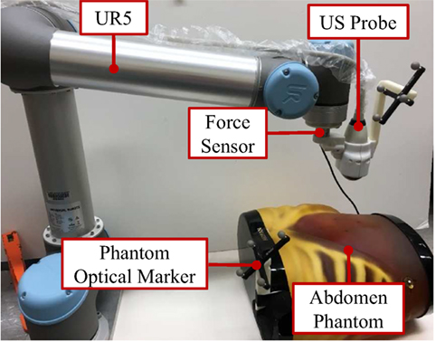
Figure 1. Robot system and experimental setup.
Figure 2 presents an overview of our proposed ultrasound-guided robot-assisted radiotherapy workflow. The workflow is separated into a planning day, where the planning images of the patient are acquired, and multiple (fractionated) treatment days, where the radiation therapy is delivered. A more detailed discussion of this workflow can be found in Bell et al. (2014) and Sen et al. (2015). In this section, we focus on the use of cooperative control within this workflow. This requires the following three forms of cooperative control: (1) unconstrained, (2) with static VFs, and (3) with dynamic VFs updated by US image feedback.
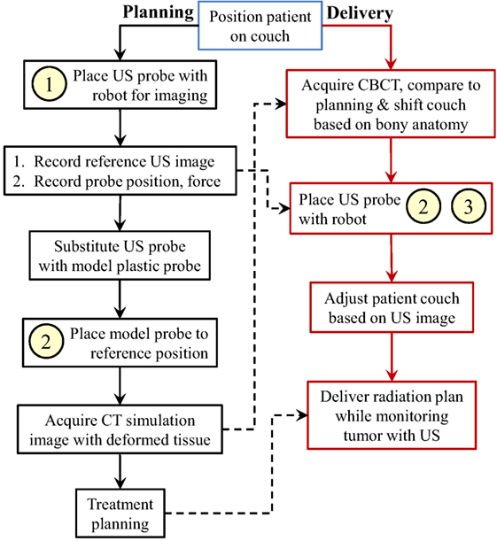
Figure 2. Proposed robotic-assisted ultrasound-guided IGRT workflow, showing use of (1) unconstrained cooperative control, (2) static virtual fixtures, and (3) dynamic virtual fixtures. Box (1) is performed by expert sonographers, and boxes (2) and (3) are performed by therapists. The dashed arrows represent data transferred from the planning day to the delivery day.
Unconstrained cooperative control is the free space manipulation of the US probe. In this mode, the operator holds the US probe and applies a force toward an intended direction of motion. Static VFs impose motion constraints; in our implementation, they are in the form of linear and torsional springs, which provide haptic feedback toward a reference US probe position and orientation, as described in Sen et al. (2013). The fixtures are called static because their parameters do not change over time. The dynamic VFs are created by updating the parameters of the static VFs, based on real-time feedback from the acquired US images. This mode is used to guide the operator to find a previously found US image. Implementation details of the unconstrained cooperative control and the VFs are presented in the next section.
The planning day of the workflow requires the presence of an expert ultrasonographer. On this day, unconstrained cooperative control, which is labeled as “1” in Figure 2, is used when the ultrasonographer tries to localize the tumor area with the US probe. Once the US image that contains the tumor is found, the ultrasonographer records the 3D US volume image that contains the tumor location (the reference US image), the contact force between the US probe and the patient (the reference force), and the position and orientation of the US probe with respect to the room frame (the goal position). Because the US probe creates artifacts in the CT images, before the planning CT scan, the ultrasonographer or the therapist retracts the US probe from the patient skin, replaces it with a geometrically identical plastic model probe, and places it back to the goal position to recreate the tissue deformation caused by the real probe. In this step, the operator utilizes cooperative control with static virtual fixtures to place the model US probe to the goal position, labeled as “2” in the planning day workflow. This procedure assumes that there is negligible motion of the patient during the brief time between the removal of the US probe and the placement of the model probe. Note that the VFs are required because ultrasound image feedback is not available with the model (fake) probe. This step can be skipped if the CT scanner provides effective artifact reduction methods, or if the artifact is not expected to interfere with treatment planning.
On the treatment days, for the beam delivery to be accurate, the placement of the US probe should create the same soft-tissue deformation as in the treatment plan. We assume that in order to achieve consistent deformation, the therapist needs to reproduce the reference US image; however, therapists are not trained for US imaging. Therefore, we propose using static VFs and dynamic VFs updated by US image feedback, labeled as “2” and “3” in the treatment day workflow, to provide the necessary guidance. Specifically, the static VFs are used to guide the therapist to a reasonable starting point (i.e., the probe location, in room coordinates, recorded during planning); then, once US image feedback is available, the system begins to dynamically update the VFs, as described in Section 2.4.
The mathematical formulation of unconstrained cooperative control starts with converting the force sensor measurements into velocity commands via multiplication by admittance gains using equation (1):
where and are the linear and angular velocity vectors in the force sensor frame, G1 … 6 are the elements of the diagonal admittance gain matrix, and and are the linear and torsional force measurements in the force sensor frame. We use non-linear admittance gains to enable fine control for smaller applied forces, while also allowing faster motions for higher applied forces (Kazanzides et al., 1992; Sen et al., 2013). Next, we convert the velocity inputs into the robot frame through the series of transformations shown in Figure 3, in which FR represents the robot frame, FPr represents the US probe tip frame (the frame origin is near the center of the convex probe surface but does not need to be precisely located, as discussed in Section 4), and FF represents the force sensor frame. We define a rotation from frame FA to FB as . Thus, in Figure 3, and represent 3 × 3 rotation matrices from FPr to FR and from FF to FPr, respectively. can be found using the forward kinematics of the robot. can be found based on the mounting of the US probe to the force sensor. Using the coordinate frame transformations in Figure 3, the velocity can be expressed in the robot frame as:
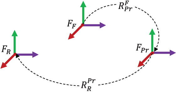
Figure 3. Unconstrained cooperative control coordinate frames.
In equation (2), and are multiplied by a 6 × 6 transformation matrix formed by the multiplication of the rotation matrices and on the diagonal. The resulting velocity vectors in the robot frame are denoted by and .
Finally, the velocity command in the robot frame is converted into angular robot joint velocities using:
where J−1 is the inverse Jacobian matrix that is a function of the robot joint angles and transforms robot frame velocities into joint velocities. The output of equation (3) is the desired joint angular velocity vector, , that is provided to the low-level controller. The dimension of and may vary depending on the number of motorized joints in the robotic system.
The VF forces and torques, and , are computed based on the standard spring model (i.e., Hooke’s Law) given by equation (4):
where Δx and Δy correspond to the linear position differences and Δθx, Δθy, and Δθz correspond to angular orientation differences of the US probe from the goal position and orientation. We do not apply a virtual spring along the Z direction (probe axis) because motion in that direction is either unconstrained during cooperative control or under force control during the final autonomous motion presented in Section 2.4. The diagonal elements, ki, correspond to the stiffnesses of the linear and torsional virtual springs. The directions of the VF forces are always toward the origin of the virtual springs.
In the last step, the VF forces and torques are integrated with the unconstrained cooperative control scheme by setting and in equation (1) as below:
where the VF forces are added to the forces applied by the operator, now called and .
We refer to the dynamic VFs as a human-in-the-loop image servoing co-manipulation strategy because the technical approach requires the same methods as image (or visual) servoing but is implemented within a cooperative control framework. This strategy, shown in Figure 4, assists a radiation therapist, who might not have received ultrasound training, to manipulate the US probe in order to achieve the reference US image. The underlying paradigm is cooperative control, where the robot holds the US probe, but moves it in response to forces exerted on the probe by the therapist. The next control layer provides haptic guidance, within the cooperative control strategy, by creating VFs in the form of linear and torsional springs that guide the therapist to the desired position and orientation, as described in Sen et al. (2013). However, in this application, the correct position and orientation are not precisely known in advance. Therefore, the novelty of our approach is in the higher-level software that dynamically updates the VFs based on real-time US image feedback. This represents an advance over our prior work (Sen et al., 2013), where the VFs were based on the reference position and orientation and were not updated.
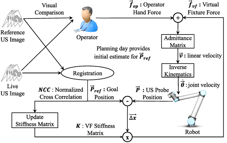
Figure 4. Block diagram of ultrasound-guided co-manipulation strategy.
The above strategy is implemented in a software architecture that consists of five main components. The first component activates the wobbler motor inside the US probe. We collect 11 US image slices with a focus depth of 9 cm and a wobbler step angle of 0.732°. The acquired 2D B-Mode US images are sent to the second software component, ImFusion Suite (ImFusion, Munich, Germany), which is a commercial medical imaging software that provides visualization and processing of medical data sets. It reconstructs the received 2D US images to form a 3D US volume based on the wobbler angle information of each 2D US image (Karamalis et al., 2009). ImFusion registers the live 3D US volume to the reference US volume that was recorded on the planning day, using a GPU-optimized mono-modal intensity-based image registration technique with the similarity measure set to Normalized Cross Correlation (NCC), the reference US volume set as a mask, and the optimization algorithm set to BOBYQA (Powell, 2009) for bound-constrained via quadratic models. The resulting rigid transformation is sent to the third component, Robot Control, which combines this transformation with the optical tracking and force measurements (from the fourth and fifth components) to generate the desired US probe motion commands. The mean update rate of the image feedback is approximately 2.5 Hz. Although the registration method supports all 6 degrees of freedom, for the experiments reported here, we enable only the 3 translation parameters. This is consistent with current practice, where many LINAC couches can only correct for translation errors, and therefore therapists rely on existing patient positioning methods to reproduce orientation. Additionally, the small size of the 3D US volume makes it more difficult to accurately estimate the orientation component; if orientation adjustment is needed, a larger 3D volume should be acquired, at the expense of a slower image update rate.
In order to dynamically update the VFs with US image feedback, the image registration output undergoes a series of transformations between the coordinate frames shown in Figure 5, in which FR is the robot frame, FPr is the US probe tip frame, Fus is the frame attached at the US probe wobbler motor center of rotation, FRef is the reference US image frame, and Freg is the live US image coordinate frame. As with rotations, we define to be a transformation (a rotation and a translation) from coordinate frame FA to FB. Therefore, to express a tumor location in the robot coordinates, FR, the transformation between the US image and the robot coordinates, , is required, and it is calculated using equation (6):
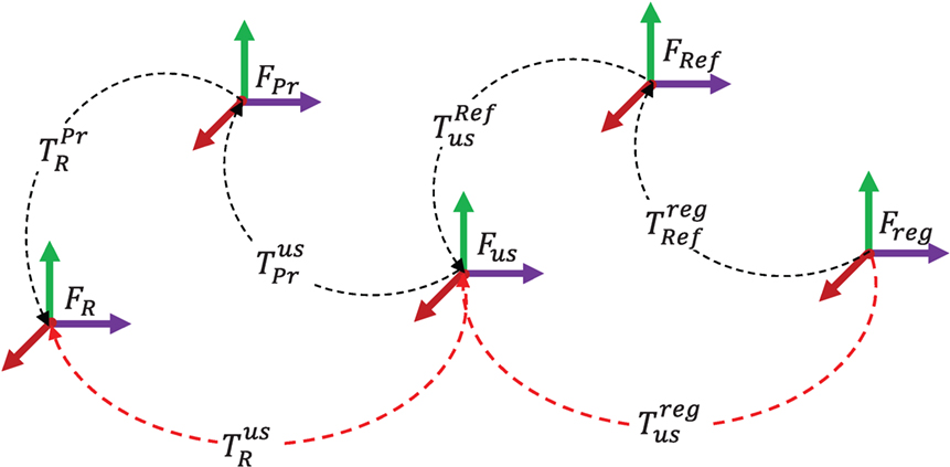
Figure 5. US image feedback coordinate frames. In order to use the US image registration output in the robot control, the transformation between the registered image frame, Freg, and the robot frame, FR, should be found (red dashed lines).
In equation (6), is computed from the forward kinematics of the robot. For a 3D US probe, is a calibration matrix that can be obtained from the probe data sheet. The other transformations in Figure 5 are considered below.
A more detailed flowchart of the co-manipulation strategy is given in Figure 6. The process uses the planning day US probe position as an initial estimate for the goal position (i.e., the origin of the VFs). On each treatment day, the therapist first brings the US probe close to the target organ area using cooperative control with virtual fixtures. Once US images are acquired, the system begins the image registration process to determine (see Figure 5) and, based on the results of the registration, may update the stiffness and/or origin of the virtual springs or make small autonomous motions. This behavior is determined by three different NCC thresholds, NCCl, NCCm, and NCCh. In our experiments, these were heuristically set to 0.65, 0.7, and 0.8, respectively. If the calculated NCC is at least NCCl, the origin of the virtual springs is changed based on the translation component of the registration, , between the current 3D US image and the reference 3D US image, after applying the following coordinate transformations to convert the translation to the robot coordinate system (see Figure 5):
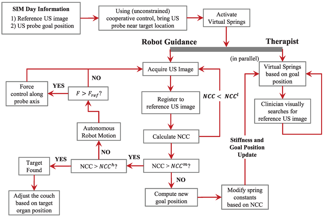
Figure 6. Treatment day US probe placement process.
Here, is given by equation (6), and is the transformation matrix of the reference US volume obtained on the planning day. To avoid an abrupt change to the VF, the translation is first scaled. In our implementation, we used a scale factor of 0.02 (i.e., 2%). Given the relatively slow registration update rate, this scale factor produced a smooth, gradual motion of the virtual spring origin. In addition, the spring stiffnesses are updated as follows:
where and uki are the nominal and updated stiffness values for the ith axis. Essentially, the spring stiffness is increased in proportion to NCC, which provides haptic feedback of the confidence in the registration. The spring stiffnesses are not changed if NCC is greater than NCCm because that is the threshold for the autonomous motion. Specifically, if the calculated NCC is between NCCm and NCCh, the system displays a dialog box on the GUI to prompt the therapist to let go of the US probe and the robot starts to move autonomously to the desired probe position. At this point, since the system has only one force sensor, it is crucial that the therapist releases the US probe because the system begins to compare the measured force to the planning day reference force, Fref; for clinical use, a more reliable transition between cooperative control and autonomous motion would be needed. Finally, the autonomous motion stops when NCC becomes larger than NCCh, implying that the live US volume is close enough to the reference US volume.
We performed six experiments with a single user (graduate student with no US training, but with significant experience with the robotic system) to validate the cooperative control strategy with dynamic VFs in a simulated radiotherapy workflow. The experimental setup, shown in Figure 1, consists of a 6-DOF UR5 robot, an Ultrasonix m4DC7-3/40 Microconvex 4D US probe, an Ultrasonix Sonix CEP US machine, an optical marker frame attached to the US probe, a plastic abdomen phantom that is an US examination training model ABDFAN (Kyoto Kagaku, Japan), an optical marker frame attached to the phantom (only used for data analysis), and a NDI Polaris optical tracker.
The experimental procedure and the data collected during the experiment are illustrated in Figure 7. The experimental procedure consists of a planning workflow, corresponding to the planning day US probe placement process, and a treatment workflow, corresponding to the treatment day US probe placement process. The net result is the computed couch shift, which is compared to the ground truth shift measured by the optical tracker.
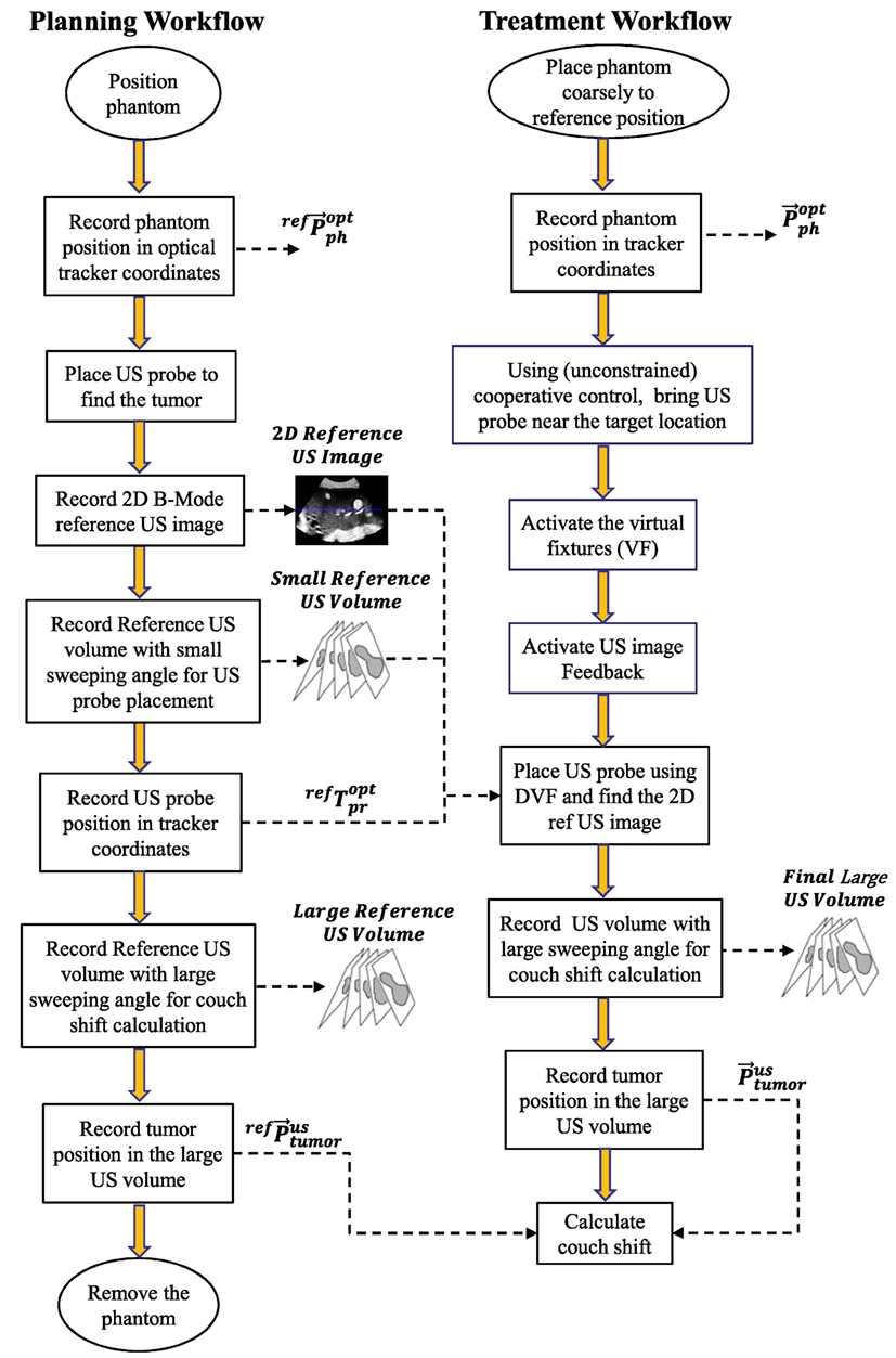
Figure 7. Experiment workflow for testing US image-based patient setup.
The planning workflow starts with positioning the abdomen phantom in the workspace of the UR5. At this point, the optical marker position attached to the phantom is recorded in optical tracker coordinates as the reference phantom position, . The US probe is then positioned to find the tumor, and a 2D B-mode US image and two 3D US images (with different sweep angles) are acquired. The 2D B-mode image will later be used in the treatment workflow for the operator’s visual comparison with the live US image. The larger 3D US volume is reconstructed from 41 2D B-mode US image slices separated by 0.732° increments. It contains the entire tumor, thus enabling accurate identification of the tumor centroid, ; this will later be used to compute the couch shift in the treatment workflow. The smaller reference 3D US volume, reconstructed from 11 2D B-mode US image slices separated by 0.732° angular increments, is registered to the real-time US image feedback during the treatment workflow. The number of slices used in the small and the large US volumes are determined experimentally, taking into account the US image feedback update rate and the wobbler angle range of the US probe. Next, the US probe optical marker position and orientation in the optical tracker coordinates is recorded as a transformation matrix, , and is used as the initial estimate for the VF centers in the treatment workflow. Finally, the phantom is removed from the workspace.
In the treatment workflow, the optical tracker stays at the same position as in the planning workflow to emulate the common room coordinate system between the planning and treatment rooms, each of which has an optical tracker mounted on the ceiling and calibrated to a defined isocenter. The workflow starts with the coarse placement of the phantom near the planning workflow location, and the position of the optical marker attached to the phantom is recorded as . The difference of the phantom position from the planning workflow emulates the patient setup error before each treatment session during radiotherapy. In the experiments, the initial patient setup error was measured as 47.6 ± 26.2 mm in translation and 5.7 6 ± 5.2° in orientation. After that, the operator tries to find the reference 2D B-Mode US image, utilizing dynamic VFs that are updated whenever the NCC between the registered US volume and the reference US volume exceeds the NCCl threshold. The system switches to autonomous motion when the NCC exceeds the NCCm threshold, and the probe placement process ends when the NCC exceeds the high threshold, NCCh, as described in Section 2.4. At this point, a large US volume scan of the target area, with the same scanning parameters as in the planning workflow, is acquired. The tumor centroid is localized in this US volume, and its position is recorded in US image coordinates as ; this is used to compute the couch shift, as described in the next section, which brings the tumor to the isocenter (i.e., in this experiment, the tumor position at which the reference image was acquired). The treatment workflow is repeated for a total of six different trials.
The coordinate systems used in the evaluation of the patient setup accuracy are shown in Figure 8, where FOpt is the optical tracker, FPh is the abdomen phantom optical marker, FPr is the US probe tip, is the US probe optical marker, and Fus is the US image coordinate frame. Note that the US probe “tip” is a point near the center of the convex probe surface but does not correspond to a specific physical feature; it provides a reference for probe position and orientation measurements with respect to the patient, as in equation (13) below. Based on the recorded data, the ground truth for the couch shift is determined by tracking the abdomen phantom position in the planning workflow and in the treatment workflow and taking their difference as in equation (9):
where is the translation component of the transformation matrix .
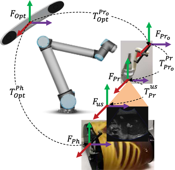
Figure 8. Experimental setup transformation map. During the experiments, the camera frame, FOpt, and the transformations and remained fixed, and the transformations and were moving.
Then, we calculate a couch shift in optical tracker coordinates based on the position differences of the tumor centroids between the reference US volume and the final US volume using:
where the transformations, , , and are shown in Figure 8, and they are the transformations between the optical tracker and the probe optical marker, the probe optical marker and the probe tip, and the probe tip and the US image coordinates, respectively. For a 3D US probe, (the rotation component of ) changes at every wobbler scan angle by a pure rotation around the lateral direction of the US probe, as given in equation (11):
where θw corresponds to the wobbler motor angle.
The transformation between the US probe and the probe optical marker, , is determined by the active echo US probe calibration method described in Guo et al. (2014). Lastly, is provided by the optical tracker.
Next, the patient setup error is found by subtracting the couch shift vectors calculated from equation (9) and (10), and taking the magnitude of the resulting position difference vector as in equation (12):
Additionally, because the phantom has not physically changed, the user’s US probe placement should ideally be the same as the reference probe placement. Thus, we can assess the subject’s probe placement performance by computing the transformation between the US probe tip and the phantom optical marker, , and comparing it to the true (reference) US probe tip transformation, , as follows:
Because the US probe tip is defined as a point near the center of the convex probe surface, intuitive measures of the probe position and orientation differences are calculated from Tdiff by taking the norm of the translation part and by finding the angular rotation from the axis angle representation of the rotation component.
We performed the planning workflow to locate a tumor in the phantom liver; Figure 9 shows the 2D B-mode image that was saved as the reference image. Figure 10 shows the middle slice of the final US volumes acquired during the treatment workflow for experiments 1 through 6. These US image slices are the result of the operator’s attempt to reproduce the reference 2D B-Mode US image shown in Figure 9. Additionally, the US image-based patient setup errors for the experiments are presented in Table 1. It is seen that the overall mean patient setup error of the experiments is less than 1.8 mm. Finally, the US probe placement position and orientation differences are presented in Table 2.
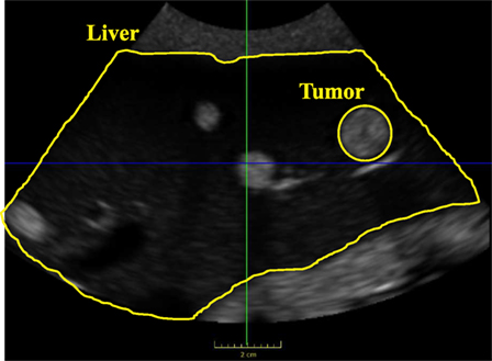
Figure 9. Reference US image used in the experiments.
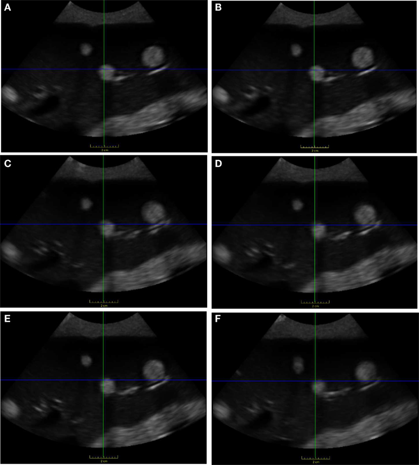
Figure 10. Final US images found after treatment workflow. US images (A–F) correspond to experiments 1–6, which are all similar to the reference US image shown in Figure 9.
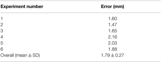
Table 1. US image-based 3D positional patient setup errors for experiments 1 through 6.
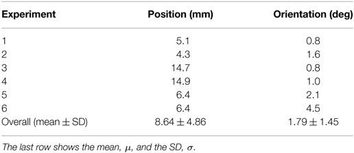
Table 2. US probe placement position and orientation difference.
The performed experiments evaluate the patient setup accuracy of the proposed clinical workflow, which uses US imaging for improved visualization of soft-tissue targets. The results show that the final US volumes acquired at the end of the treatment workflow can be used to accurately place the tumor at the planning day position, which corresponds to the isocenter of the radiotherapy beams. Specifically, the mean US image-based patient setup error, utilizing dynamic virtual fixtures updated by US image feedback, is 1.8 mm. This phantom study does not include the effects of breathing or other physiologic motion, so clinical results are likely to be less accurate.
Possible sources of error in these experiments include US probe calibration (Guo et al., 2014), which is on the order of 1 mm, and manual detection of the tumor centroids. Furthermore, determining couch shift based on the difference in centroids is reasonable for the mostly spherical tumors present in the phantom, but a more sophisticated method is likely to be needed in clinical practice, where tumor shapes may be more complex.
An interesting observation during the experiments is that the proposed co-manipulation strategy truly became a partnership between human and machine. While the machine updated the virtual fixtures to guide the human toward the goal, we also observed cases where the intensity-based registration algorithm got stuck in a local minimum. In those cases, the human could easily detect a poor feature match between the current and reference US images and, by pushing against the virtual springs, was able to dislodge the system from the local minimum.
Lastly, it is seen in Table 2 that the US probe placement difference is 8.64 ± 4.86 mm in translation and 1.79 ± 1.45° in rotation. The rotation difference is lower than the translation difference because the phantom is designed to lay flat on a table and therefore removing and replacing it (to emulate patient setup) does not cause significant orientation changes. The translation and rotation differences may be clinically important, depending on the margin that was assumed around the US probe during planning of the treatment beams. For example, if the treatment plan includes a beam that passes within 5 mm of the US probe, it is necessary for the position difference to be less than 5 mm, and thus the US probe should be moved closer to the reference position and orientation to avoid irradiating the probe. In this case, after applying the couch shift, there would be a second phase of probe positioning where the therapist moves the probe toward the reference pose and attempts to achieve an acceptable compromise between reproducing the reference US image and placing the US probe within the margins specified during treatment planning. This could be implemented with yet another variation of cooperative control; specifically, the probe motion could be constrained by a line VF between the current position and the recorded reference position. Note that it is possible to command the robot to move the US probe to the reference position and orientation, which would achieve a measured placement difference of 0 (of course, there would still be a small placement difference due to calibration errors). The key point is that there may exist a trade-off between reproducing the reference US image and bringing the probe back to the reference position and orientation. This trade-off must be resolved by the therapist based on the treatment requirements, including the positioning of beams with respect to the US probe.
This paper presented a novel cooperative control strategy with US image feedback for the integration of US imaging in the planning and radiation treatment phases of image-guided radiation therapy for soft-tissue targets, especially in the upper abdomen. The novel control algorithm provides real-time guidance to locate soft-tissue targets for radiotherapy, enabling users with minimal US experience to find an US image that was previously found by an expert. The algorithm is intended to provide accurate and repeatable patient setup on each radiotherapy treatment day. The guidance to the users is in the form of haptic feedback, utilizing VFs whose parameters are tuned by real-time US image feedback during the placement of the US probe. After the US probe placement, the US imaging is used to improve the patient setup by visualizing the soft-tissue target, rather than by relying on the bony anatomy that is visible in CBCT images.
The robot control algorithm was validated by performing experiments with a plastic abdomen phantom. Our results show that the US image-based patient setup error utilizing dynamic virtual fixtures updated by US image feedback remains less than 2.2 mm, which is promising as an alternative to current clinical practice with bony anatomy-based patient setup. The results are important because the robotic guidance with US image feedback can eliminate the need for clinicians with US expertise during treatment. Our future work includes performing a multiuser study to compare the performance of the proposed method with dynamic VFs to a baseline case of free-hand probe placement.
JW, PK, and II proposed the initial concept for this project. HS developed the algorithm details, including the update of the virtual fixtures based on the US image registration output, with input from PK, JW, II, and KD. HS and II designed the CAD of the US probe connection mechanism, and II manufactured the components. HS and PK designed the high-level component-based software architecture, and HS implemented the system software. AC and EB provided software assistance for the MUSiiC Toolkit, and AC assisted with the calibration of the US probe. HS and KD prepared the experiment setup under the supervision of PK, II, and JW. Finally, HS performed the analysis of the collected data.
JW received royalty payments from Elekta AB on CBCT image guidance. All other authors declare that the research was conducted in the absence of any commercial or financial relationships that could be construed as a potential conflict of interest.
Wolfgang Wein (ImFusion GmbH) and Bernhard Fuerst provided software assistance for ImFusion Suite. Muyinatu A. Lediju Bell contributed to the development of the workflow and the experiment design, and Russell H. Taylor provided guidance and mentorship for the experiments conducted.
This work was supported in part by NIH R01 CA161613 and in part by Elekta AB.
Abolmaesumi, P., Salcudean, S., and Zhu, W. (2000). “Visual servoing for robot-assisted diagnostic ultrasound,” in Intl. Conf. of IEEE Engineering in Medicine and Biology Society (EMBC), Vol. 4 (Chicago: IEEE), 2532–2535.
Ammann, N. (2012). Robotized 4D Ultrasound for Cardiac Image-Guided Radiation Therapy. Master’s thesis, University of Lüebeck, Lübeck.
Bell, M. A. L., Byram, B. C., Harris, E. J., Evans, P. M., and Bamber, J. C. (2012). In vivo liver tracking with a high volume rate 4D ultrasound scanner and a 2D matrix array probe. Phys. Med. Biol. 57, 1359–1374. doi: 10.1088/0031-9155/57/5/1359
Bell, M. A. L., Sen, H. T., Iordachita, I. I., Kazanzides, P., and Wong, J. (2014). In vivo reproducibility of robotic probe placement for a novel US-CT image-guided radiotherapy system. J. Med. Imaging (Bellingham) 1, 025001.1–025001.9. doi:10.1117/1.JMI.1.2.025001
De Luca, V., Benz, T., Kondo, S., König, L., Lübke, D., Rothlübbers, S., et al. (2015). The 2014 liver ultrasound tracking benchmark. Phy. Med. Biol. 60, 5571–5599. doi:10.1088/0031-9155/60/14/5571
Guo, X., Cheng, A., Zhang, H. K., Kang, H.-J., Etienne-Cummings, R., and Boctor, E. M. (2014). “Active echo: a new paradigm for ultrasound calibration,” in Medical Image Computing and Computer-Assisted Intervention (MICCAI) Springer LNCS 8674, Part II, Boston, eds P. Golland, N. Hata, C. Barillot, J. Hornegger, and R. Howe (Heidelberg: Springer), 397–404.
Harris, E. J., Miller, N. R., Bamber, J. C., Symonds-Tayler, J. R. N., and Evans, P. M. (2010). Speckle tracking in a phantom and feature-based tracking in liver in the presence of respiratory motion using 4D ultrasound. Phys. Med. Biol. 55, 3363–3380. doi:10.1088/0031-9155/55/12/007
Janvier, M.-A., Merouche, S., Allard, L., Soulez, G., and Cloutier, G. (2014). A 3-D ultrasound imaging robotic system to detect and quantify lower limb arterial stenoses: in vivo feasibility. Ultrasound Med. Biol. 40, 232–243. doi:10.1016/j.ultrasmedbio.2013.08.010
Karamalis, A., Wein, W., Kutter, O., and Navab, N. (2009). “Fast hybrid freehand ultrasound volume reconstruction,” in SPIE Proceedings Vol. 7261, Medical Imaging 2009: Visualization, Image-Guided Procedures, and Modeling, eds M. I. Miga and K. H. Wong (Lake Buena Vista, FL), 726114.1–726114.8.
Kazanzides, P., Zuhars, J., Mittelstadt, B., and Taylor, R. (1992). “Force sensing and control for a surgical robot,” in IEEE Intl. Conf. on Robotics and Automation (ICRA) (Nice, France: IEEE), 612–617.
Kuhlemann, I. (2013). Force and Image Adaptive Strategies for Robotised Placement of 4D Ultrasound Probes. Master’s thesis, University of Lübeck, Lübeck.
Mebarki, R., Krupa, A., and Chaumette, F. (2008). “Image moments-based ultrasound visual servoing,” in IEEE Intl. Conf. on Robotics and Automation (ICRA) (Pasadena: IEEE), 113–119.
Mebarki, R., Krupa, A., and Chaumette, F. (2010). 2-D ultrasound probe complete guidance by visual servoing using image moments. IEEE Trans. Robot. 26, 296–306. doi:10.1109/TRO.2010.2042533
Meng, B., and Liu, J. (2015). “Robotic ultrasound scanning for deep venous thrombosis detection using RGB-D sensor,” in IEEE Intl. Conf. on Cyber Technology in Automation, Control, and Intelligent Systems (CYBER) (Shenyang: IEEE), 482–486.
Nadeau, C., and Krupa, A. (2010). “A multi-plane approach for ultrasound visual servoing: application to a registration task,” in IEEE/RSJ Intl. Conf. on Intelligent Robots and Systems (IROS) (Taipei: IEEE), 5706–5711.
Nadeau, C., and Krupa, A. (2013). Intensity-based ultrasound visual servoing: modeling and validation with 2-D and 3-D probes. IEEE Trans. Robot. 29, 1003–1015. doi:10.1109/TRO.2013.2256690
Novotny, P. M., Stoll, J., Dupont, P. E., and Howe, R. D. (2007). “Real-time visual servoing of a robot using three-dimensional ultrasound,” in IEEE Intl. Conf. on Robotics and Automation (ICRA) (Rome: IEEE), 2655–2660.
Pahl, C., and Supriyanto, E. (2015). “Design of automatic transabdominal ultrasound imaging system,” in Intl. Conf. on Methods and Models in Automation and Robotics (MMAR) (Miedzyzdroje: IEEE), 435–440.
Powell, M. J. (2009). The BOBYQA Algorithm for Bound Constrained Optimization without Derivatives. Technical Report DAMTP 2009/NA06, Centre for Mathematical Sciences. Cambridge: University of Cambridge.
Sauvée, M., Poignet, P., and Dombre, E. (2008). Ultrasound image-based visual servoing of a surgical instrument through nonlinear model predictive control. Int. J. Rob. Res. 27, 25–40. doi:10.1177/0278364907082269
Sawada, A., Yoda, K., Kokubo, M., Kunieda, T., Nagata, Y., and Hiraoka, M. (2004). A technique for noninvasive respiratory gated radiation treatment system based on a real time 3D ultrasound image correlation: a phantom study. Med. Phys. 31, 245–250. doi:10.1118/1.1634482
Schlosser, J., Salisbury, K., and Hristov, D. (2010). Telerobotic system concept for real-time soft-tissue imaging during radiotherapy beam delivery. Med. Phys. 37, 6357–6367. doi:10.1118/1.3469027
Schlosser, J., Salisbury, K., and Hristov, D. (2011). Tissue displacement monitoring for prostate and liver IGRT using a robotically controlled ultrasound system. Med. Phys. 38, 3812. doi:10.1118/1.3613355
Sen, H. T. (2016). Robotic System and Co-Manipulation Strategy for Ultrasound Guided Radiotherapy. PhD thesis, The Johns Hopkins University, Baltimore, MD.
Sen, H. T., Bell, M. A. L., Iordachita, I., Wong, J., and Kazanzides, P. (2013). “A cooperatively controlled robot for ultrasound monitoring of radiation therapy,” in IEEE/RSJ Intl. Conf. on Intelligent Robots and Systems (IROS) (Tokyo: IEEE), 3071–3076.
Sen, H. T., Bell, M. A. L., Zhang, Y., Ding, K., Wong, J., Iordachita, I., et al. (2015). “System integration and preliminary in-vivo experiments of a robot for ultrasound guidance and monitoring during radiotherapy,” in IEEE Intl. Conf on Advanced Robotics (ICAR) (Istanbul: IEEE), 53–59.
Stoll, J., Novotny, P., Howe, R., and Dupont, P. (2006). “Real-time 3D ultrasound-based servoing of a surgical instrument,” in IEEE Intl. Conf. on Robotics and Automation (ICRA) (Orlando: IEEE), 613–618.
Trakul, N., Koong, A. C., and Chang, D. T. (2014). Stereotactic body radiotherapy in the treatment of pancreatic cancer. Semin. Radiat. Oncol. 24, 140–147. doi:10.1016/j.semradonc.2013.11.008
Troccaz, J., Menguy, Y., Bolla, M., Cinquin, P., Vassal, P., Laieb, N., et al. (1993). Conformal external radiotherapy of prostatic carcinoma: requirements and experimental results. Radiother. Oncol. 29, 176–183. doi:10.1016/0167-8140(93)90244-3
Vitrani, M.-A., Mitterhofer, H., Morel, G., and Bonnet, N. (2007). “Robust ultrasound-based visual servoing for beating heart intracardiac surgery,” in IEEE Intl. Conf. on Robotics and Automation (ICRA) (Rome: IEEE), 3021–3027.
Vitrani, M.-A., Morel, G., and Ortmaier, T. (2005). “Automatic guidance of a surgical instrument with ultrasound based visual servoing,” in IEEE Intl. Conf. on Robotics and Automation (ICRA) (Barcelona: IEEE), 508–513.
Keywords: cooperative control, virtual fixtures, human-in-the-loop image servoing, robot-assisted radiotherapy, ultrasound-guided radiotherapy
Citation: Şen HT, Cheng A, Ding K, Boctor E, Wong J, Iordachita I and Kazanzides P (2016) Cooperative Control with Ultrasound Guidance for Radiation Therapy. Front. Robot. AI 3:49. doi: 10.3389/frobt.2016.00049
Received: 12 April 2016; Accepted: 28 July 2016;
Published: 15 August 2016
Edited by:
Valentina Vitiello, Imperial College London, UKReviewed by:
Ka-Wai Kwok, University of Hong Kong, Hong KongCopyright: © 2016 Şen, Cheng, Ding, Boctor, Wong, Iordachita and Kazanzides. This is an open-access article distributed under the terms of the Creative Commons Attribution License (CC BY). The use, distribution or reproduction in other forums is permitted, provided the original author(s) or licensor are credited and that the original publication in this journal is cited, in accordance with accepted academic practice. No use, distribution or reproduction is permitted which does not comply with these terms.
*Correspondence: Peter Kazanzides, cGthekBqaHUuZWR1
Disclaimer: All claims expressed in this article are solely those of the authors and do not necessarily represent those of their affiliated organizations, or those of the publisher, the editors and the reviewers. Any product that may be evaluated in this article or claim that may be made by its manufacturer is not guaranteed or endorsed by the publisher.
Research integrity at Frontiers
Learn more about the work of our research integrity team to safeguard the quality of each article we publish.