
95% of researchers rate our articles as excellent or good
Learn more about the work of our research integrity team to safeguard the quality of each article we publish.
Find out more
ORIGINAL RESEARCH article
Front. Robot. AI , 10 August 2016
Sec. Biomedical Robotics
Volume 3 - 2016 | https://doi.org/10.3389/frobt.2016.00048
This article is part of the Research Topic Cooperative Control Techniques in Surgical Robotics View all 5 articles
This work presents a new discrete-time adaptive-predictive control algorithm for a system with force disturbance and input delay. This scenario is representative of a mechatronic device for percutaneous intervention with pneumatic actuation and long supply lines which is controlled remotely in the presence of an unknown external force resulting from needle-tissue interaction or gravity. The ultimate goal of this research is the robotic-assisted percutaneous intervention of the liver under Magnetic Resonance Imaging (MRI) guidance. Since the control algorithm is intended for a digital microcontroller, it is presented in the discrete-time form. The controller design is illustrated for a 1 degree-of-freedom system and is conducted with a modular approach combining position control, adaptive disturbance compensation, and predictive control. The controller stability is analyzed and the effect of the input delay and of the tuning parameters is discussed. The controller performance is assessed with simulations considering a disturbance representative of needle insertion forces. The results indicate that the adaptive-predictive controller is effective in the presence of a variable disturbance and of a known or variable input delay.
Mechatronics instruments for magnetic resonance imaging (MRI)-guided intervention allow conducting complex procedures that would otherwise be very time consuming and error prone (Tse et al., 2012; Yang et al., 2014; Franco et al., 2016). Typically, a specially designed robot operates inside the scanner bore where the patient cannot be easily accessed (Yang et al., 2014). In order to comply with the restrictive safety requirements of the MRI environment, special actuation methods should be employed. Among these, pneumatic actuation represents a clean, affordable, and safe solution. Hence, it has been used in several robots for MRI-guided intervention (Melzer et al., 2008; Stoianovici et al., 2014). In order to minimize image degradation, several systems employ a control unit and a power source located outside the MRI room, supplying the robot through long transmission lines (Yang et al., 2011; Iranpanah et al., 2015; Franco et al., 2016). Simultaneously, the clinicians operate a master unit from the control room, where the intra-operative MR images are displayed for guidance (Franco and Ristic, 2015). Since needle insertions with haptic feedback offer several advantages in terms of faster, more accurate, and potentially safer procedures, master-slave systems are instrumented with sensors to measure the needle insertion forces and reflect them on the operator. In most robots for MRI-guided percutaneous intervention, the needle insertion stage is a 1 degree-of-freedom (DOF) mechanism corresponding to the translation along the needle axis (Melzer et al., 2008; Tse et al., 2012; Li et al., 2014; Stoianovici et al., 2014). While recent research has proposed the use of steerable needles for MRI-guided percutaneous intervention (Comber et al., 2016), more work is required before this solution could become clinically viable.
Notably, pneumatic actuation with long supply lines introduces an input delay in the system, which has typically been disregarded for the purpose of point-to-point positioning tasks (Yang et al., 2011). However, input delay could lead to oscillations in tracking tasks and consequently degrade the haptic feedback to the operator. Additionally, the robot typically operates in an unstructured environment and is subject to force disturbances. The resulting scenario poses remarkable challenges from a control perspective. While several control approaches have been proposed to address these issues individually (Slotine and Li, 1991; Krstic et al., 1995), their intersection is still an active area of research (Monaco and Normand-Cyrot, 2015; Pyrkin and Bobtsov, 2015). Adaptive control methods and robust control techniques have been used for systems with parameter uncertainty (Slotine and Li, 1991). Among the adaptive control methods, Immersion and Invariance (I&I) (Astolfi et al., 2008) has several advantages, such as the reduced number of parameters, which simplifies tuning, and its modularity, which allows higher design flexibility. While classical non-linear adaptive controllers predominantly employ the adaptive Backstepping approach, the I&I method does not rely on linear parameterization, hence the resulting adaptation law can be constructed independently of the control law (Astolfi et al., 2008). Previous research on teleoperation has mostly been concerned with the communication delay between the master and the slave units (Pan et al., 2014), which are typically controlled separately in situ. Instead, addressing the challenge posed by input delay requires a prediction of the system behavior based on a reference model, which can be challenging in the presence of disturbances. Additionally, most research on predictive control has been conducted for continuous-time linear systems (Krstic, 2010). The case of a linear system with unmeasurable states was addressed in Zhou (2014) employing an observer. A hybrid continuous/discrete-time system with input delay was considered in Monaco and Normand-Cyrot (2015), and predictive control was expressed as a special case of I&I adaptation. A continuous-time adaptive algorithm for a linear system with input delay and sinusoidal disturbance was recently proposed in Pyrkin and Bobtsov (2015). Nevertheless, discrete-time implementations are required for digital microcontrollers. A discrete-time predictor was presented in Karafyllis and Krstic (2013), which employed a Lyapunov redesign method in order to address the presence of system uncertainties. However, the control scheme was based on the assumption of bounded disturbances, which might not be realistic in unstructured environments.
The main contribution of this work is the design of a new discrete-time adaptive-predictive control algorithm for a system with force disturbance and input delay. This scenario is relevant to systems in which the controller and the power source are located remotely from the actuator, as in the case of robots for percutaneous intervention under MRI-guidance (Yang et al., 2014; Franco et al., 2016). The proposed control scheme extends the predictive controller in Karafyllis and Krstic (2013) to tracking tasks and removes the assumption of bounded disturbances. This is particularly advantageous in the case of unstructured environments such as percutaneous intervention. To this end, the I&I adaptive method in its discrete-time form (Yalcin and Astolfi, 2011) is implemented for a system with additive disturbance and input delay. The controller design is illustrated following a modular approach and considering a 1 DOF system, which is representative of the needle insertion stage in robotic devices for MRI-guided percutaneous intervention with pneumatic actuation (Yang et al., 2011). The stability of the control scheme is analyzed, and the effects of the input delay are discussed. The performance of the controller is assessed with simulations considering a disturbance representative of typical needle insertion forces. The benefits of the predictive control and of the adaptive disturbance compensation as well as the influence of the parameters are highlighted considering different scenarios.
While input delay is an ubiquitous phenomenon in systems characterized by transportation or transmission, the particular case of a pneumatically actuated master-slave system for percutaneous intervention operating with an impedance-control scheme is considered here as a motivating example for the new adaptive-predictive control algorithm. According to this paradigm, the operator sets the position of the master unit, which becomes the reference for the slave actuator that is powered and controlled from a remote location. Simultaneously, the interaction force between the slave and the environment is measured with a sensor and is reflected on the master actuator in order to provide haptic feedback to the operator (Figure 1). Since the needle insertion forces depend primarily on the insertion depth (van Gerwen et al., 2012), they are closely related to the position of the slave actuator. Consequently, it is essential for a correct haptic feedback that the slave accurately tracks the position of the master. This objective is achieved with a suitable choice of actuators and with performing control algorithms. Robotic devices for percutaneous intervention have employed either non-backdrivable actuators (Tse et al., 2012) or compliant actuators (Iranpanah et al., 2015; Franco et al., 2016). Non-backdrivable actuators can hold their position regardless of the external forces, within their design limits. Compliant actuators allow force transfer between the environment and the actuator itself, and are increasingly employed in human-robot interactions and robotic-assisted surgery due to their inherent safety (Gerboni et al., 2015). However, more advanced control schemes are necessary in order to achieve high position accuracy in the presence of force disturbances.
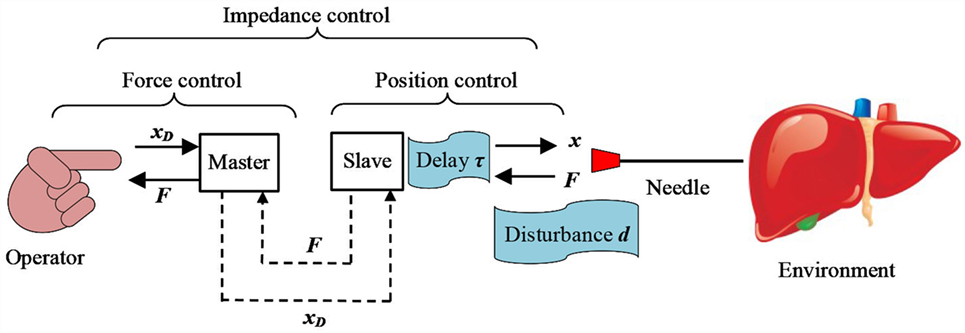
Figure 1. Schematic of a master-slave system for percutaneous intervention. Input delay τ and force disturbance d are highlighted as the two main control challenges for the slave actuator.
This section introduces a compliant pneumatic actuator supplied by proportional pressure regulators (e.g., Tecno Basic, Hoerbiger), which is modeled as a second-order system with mass m and damping coefficient b (Yang et al., 2011).
The control input u corresponds to the pressure relative to atmosphere acting on the cylinder chamber of surface A, while the term d > 0 is the force disturbance, which includes actuator specific un-modeled effects, such as gravity or friction, and interaction forces with the environment (Figure 2). The term p0 is the pressure acting in the opposite cylinder chamber of surface a. In the absence of disturbances, the cylinder extends if uA > p0a and retracts if uA < p0a. The damping coefficient b > 0 is assumed known. The long transmission lines introduce an input delay τ due to the pressure propagation at the speed of sound (Yang et al., 2011). Without loss of generality, the mass m and the area A are assumed unitary and are omitted in the rest of the paper in order to simplify the notation. Furthermore, the pressure p0 is set constant as in Franco et al. (2016) and the force p0a is included in the lumped disturbance d. As a result of these simplifications, the system is presented in a similar form to Karafyllis and Krstic (2013) and Monaco and Normand-Cyrot (2015). While the system (Eq. 1) has a linear structure, the control algorithm presented in the coming sections is designed using a general approach that is valid in principle for a non-linear system. Rewriting Eq. 1 in the state space form and converting it in its discrete-time counterpart with the Euler method we obtain:
The terms x1, x2 are the position and the velocity of the actuator. The input delay τ is assumed to be a multiple of the sampling period T. In the rest of the paper, the time dependency is indicated as follows for brevity:
The following sections present the position control algorithm, the adaptive controller, and the predictive controller, leading to the main contribution represented by the new adaptive-predictive control algorithm.
The aim of the control scheme is having the system (Eq. 2) track a prescribed position x1D. In particular, the following trajectory is considered here, where x2D and x3D represent the prescribed velocity and acceleration:
For better clarity, the control law is initially constructed for the ideal case of known force d* and null input delay τ = 0. According to Slotine and Li (1991), the auxiliary variable S representing the tracking error as a combination of position and velocity errors is introduced:
The term c1 > 0 is the first design parameter in this control scheme. An analogy can be drawn between the structure of Eq. 5 and that of a low-pass filter with the position error (x1D − x1) as input (Slotine and Li, 1991). In this perspective, c1 can be interpreted as the filter bandwidth in Eq. 5 and should be small in comparison to the high-frequency un-modeled system dynamics. In particular, a smaller value of c1 results in a more damped control action (see Results). In order to design a control law that satisfies the tracking condition S = 0, we define the following Lyapunov function candidate:
In the continuous-time situation, the control input should make the derivative of the Lyapunov function candidate negative definite in order to achieve null tracking error. Similarly, in the discrete-time case, the function V1 should decrease at each time step (Karafyllis and Krstic, 2013):
Substituting Eqs 2, 4, and 5 into Eq. 7, we can rewrite it as:
A suitable choice of the control law u that verifies Eq. 7 is:
The term c2 > 0 is the second design parameter. A larger value of c2 results in a more responsive control action. Substituting Eq. 9 into Eq. 8, we obtain:
Since V1 is positive definite and decreasing at each time step, we can conclude that the tracking error converges to 0. A parallel can be drawn between the parameters 1/c1, c2 and the derivative and the proportional gains in a PID controller. Consequently, the tuning methods valid for PID can be used as a reference for Eq. 9. Additionally, in case of a input delay, NT (Slotine and Li, 1991) suggests choosing c1 < 1/(3NT) to reduce oscillations.
In this section, the disturbance d is considered unknown and constant over the sampling interval T, and is estimated adaptively using the I&I method in the discrete-time form (Yalçin and Astolfi, 2012). Differently from robust control schemes (Pan et al., 2014) such as Sliding Mode Control (SMC) (Slotine and Li, 1991), adaptive control does not require assumptions on the bound of the disturbance. This is particular advantageous if the actuator operates in an unstructured environment, as in the case of percutaneous interventions. According to I&I, an unknown parameter ϑ is estimated as the sum of a state-dependent term βϑ and of a state-independent term . The estimation error z, which represents the difference between the estimated parameter and its actual value, is defined for system Eq. 2) as:
The terms , βd are the state-independent part and the state-dependent part of the disturbance estimate. In this case, we can already conclude that βd does not depend on x1 observing that the disturbance d only appears in the second part of Eq. 2, hence Eq. 11 is written as a function of x2. The control objective consists in having the estimation error converge to 0. In the continuous-time situation, this is achieved choosing an appropriate Lyapunov function candidate V2 = z2 and ensuring that the adaptation law makes its derivative negative definite. In the discrete-time case, this condition corresponds to showing that V2 decreases at each time step. Calculating Eq. 11 for the new time step we obtain:
Substituting Eqs 2 and 11 into Eq. 12, the convergence condition can be expressed as:
Exploiting the structure of Eq. 13, the state-independent term + is chosen as:
Substituting Eq. 14 into Eq. 13 we obtain:
A suitable choice of βd that verifies Eq. 15 is βd (x2) = − c3 < 0, where c3 < 1/T is the design parameter responsible for adaptation. Larger values of c3 result in a faster convergence of the parameter estimate to the actual value, which is usually desirable. However, this is not always the case in the presence of input delay, as discussed in Section “Results.”
Since V2 is positive definite and decreases at each time step with the chosen adaptation law, we can conclude that the estimation error z converges to 0. The control law Eq. 9) with the adaptive algorithm (Eq. 14) becomes:
Although the adaptive control law (Eq. 16) is in general non-linear, it can be shown that with appropriate assumptions on the disturbance d it simplifies into an integral term (Franco and Ristic, 2015). Consequently, an analogy can be drawn between the control scheme (Eq. 16) and a PID controller, as previously mentioned in Section “Position Control.”
This section considers a nominal input delay τ in Eq. 2 and presents a discrete-time predictive control algorithm inspired by Karafyllis and Krstic (2013) and designed for a tracking problem. Initially, the case τ = T with known force d* is considered, and the system (Eq. 2) is rewritten introducing the term y1 as:
The baseline control law (Eq. 9) for the un-delayed system corresponding to the first two equations in Eq. 17 is:
The control input is computed rewriting (Eq. 18) for the next time step:
Notably, Eq. 19 contains the future values of the states, which can however be computed form (Eq. 17). The convergence of the closed loop system consisting of Eqs 17–19 to the target dynamics will now be verified based on Lemma 2.1 in Karafyllis and Krstic (2013). Considering that the un-delayed system (Eq. 2) is stabilized by the control law (Eq. 9) according to the Lyapunov function candidate (Eq. 7), the following Lyapunov function candidate is proposed for the generic case τ = NT, where k is an arbitrary positive constant:
Computing Eq. 20 with N = 1 for the new time step we obtain:
Substituting Eqs 4, 5, and 17–19 into Eq. 21, we obtain:
Substituting Eq. 18 in Eq. 20 and comparing it with Eq. 22, the convergence is proved:
System (Eq. 17) can be expressed for the generic case τ = NT as:
The control law for the system (Eq. 24) is based on Eqs 18 and 19, which are expressed recursively for i = 1, … , N + 1:
The control input is obtained at the last step with . Notably, the algorithm (Eq. 25) assumes that the target trajectory (Eq. 4) is known N time steps in advance. The convergence of the closed loop system (Eqs 24 and 25) to the target dynamics can be proved by induction, based on the case τ = T. In particular, condition (Eq. 23) is verified for the Lyapunov function candidate (Eq. 20) with N > 1.
The general case of unknown disturbance d is considered for the system (Eq. 24) and the adaptive control law (Eq. 16) is combined with the predictive control (Eq. 25). The case τ = T is considered first, and the estimation error z is defined as in Eq. 11. The adaptive control law for the un-delayed system is given by Eq. 16, replacing u with y1:
By analogy with Eq. 19, the adaptive-predictive control law for this initial case becomes:
Since by construction, the I&I adaptation law is decoupled from the control law (see Adaptive control), the convergence of the estimation error z to zero for τ = T can be proved similarly to the un-delayed case simply replacing u with y1 in Eqs 13–15.
The effect of the estimation error z on the closed loop system (Eq. 17, 26) will now be assessed reevaluating the Lyapunov function candidate (Eq. 20), where d is considered unknown. Substituting Eqs 17, 26, and 27 into and regrouping the terms we obtain:
Differently from the un-delayed case (Eq. 6), the estimation error appears in the Lyapunov function candidate (Eq. 28). Notably, z converges to 0 due to the adaptation law (Eq. 26), assuming that d remains constant during τ. Computing (Eq. 28) for the new time step, we obtain:
Substituting Eqs 17, 26, and 27 into Eq. 29, we obtain:
Completing the squares and considering that z+ = z (1 − c3T) due to the adaptation law (Eq. 26), Eq. 30 becomes:
At this point, the following inequalities, which hold , are introduced:
Expression (Eq. 31) is then rewritten according to (Eq. 32) as:
Compared to Eq. 28, two additional terms that depend on the estimation error z appear in Eq. 33. Reevaluating the convergence condition (Eq. 23) we obtain:
Completing the squares on the right side of (Eq. 34), introducing the inequality , and comparing the corresponding terms, we obtain:
The first inequality refers to the un-delayed system (Eq. 2) and holds on condition that the estimation error converges to 0. Notably, the factorization in Eq. 35 highlights that a large sampling interval T is detrimental to the convergence, while a small T favors it. The last two inequalities originate in the presence of the input delay τ = T. In particular, the second inequality refers to the tracking condition and depends solely on c2. Instead, the third inequality refers to the estimation error and depends on the sum (c2 + c3). This result shows that, while the control scheme (Eqs 26 and 27) does not introduce additional parameters compared to the un-delayed case (Eq. 16), more limitations arise in the parameter choice. Finally, the presence of the estimation error z in the last inequality suggests that, in accordance with Karafyllis and Krstic (2013), the system becomes more sensitive to uncertainties in the presence of input delays.
The adaptive-predictive control law for the general case τ = NT is derived from Eqs 26 and 27, which are expressed recursively for i = 1, … , N + 1:
Similarly to Eq. 25, the control input corresponds to u = yN+1. Differently from the adaptive controller (Eq. 16), the control algorithm (Eq. 36) is a recursive relation computed over N time steps. In particular, the disturbance, which is estimated adaptively, is assumed constant throughout the input delay τ. This assumption is more stringent than the one made for the adaptive controller (Eq. 16). Notably, the adaptive-predictive control (Eq. 36) also proved effective for a variable input delay τ ≤ NT (see Results). Similarly to the predictive controller (Eq. 25), the convergence of the closed loop system (Eqs 24 and 36) to the target dynamics can be proved by induction based on the case τ = T previously considered (see Predictive Control).
The system (Eq. 2) was modeled in Matlab and the performance of the control algorithm was assessed with simulations. A fix step of 10 μs was employed to simulate the system dynamics while the control input was refreshed every T = 1 ms. This corresponds to a sampling frequency of 1 kHz, which is representative of that typically used in motion control and teleoperation (Pan et al., 2014; Franco et al., 2016). The duration of all simulations was set to 3 s with the reference trajectory starting at 0.5 s.
The nominal values of the damping coefficient b, the disturbance d, and the input delay N are listed in Table 1, together with the control parameters c1, c2, and c3. The parameters c1, c2, and c3 were tuned in order to achieve a rise time shorter than 0.15 s (from 10 to 90% of the step amplitude) and a settling time shorter than 0.2 s (within 5% of the step amplitude) with null steady-state-error and overshoot smaller than 1%. Additionally, different values of c3 were also employed in order to highlight the effects of this parameter on the controller performance. Four different scenarios were considered: the absence of disturbance and of input delay representing the baseline condition, the presence of either disturbance or input delay, and the combination of both. Simulations were conducted for each condition considering a step signal and a ramp as reference trajectories. In particular, the step response is a standard way of comparing control algorithms, while the ramp trajectory is representative of needle insertions. The slope of the ramp is 10 mm/s, corresponding to typical needle insertion speeds in percutaneous interventions.
Initially, the control scheme (Eq. 9) was assessed, assuming null input delay and null force d* = 0 in order to establish a reference condition. The system response for both reference trajectories is depicted in Figure 3. The steady state error, the settling time, and the rise time for the step command and the root-mean-square error (RMSE) for the ramp trajectory are reported in Table 2. These values meet the performance specifications previously defined, confirming that the controller parameters are tuned appropriately.
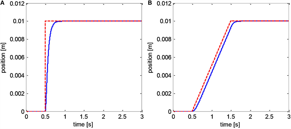
Figure 3. Baseline controller (Eq. 9): step response (A); ramp trajectory (B). Reference position is dashed red, actuator position is solid blue.
The adaptive control scheme (Eq. 16) was then assessed with a disturbance d = 1 + 100x1 + 10x2 sum of a constant term, of a term proportional to the displacement, and of a term proportional to the insertion speed. This disturbance model reflects the fact that needle insertion forces depend primarily on insertion depth and in second instance on the insertion speed, while the magnitude of the disturbance is representative of needle insertion forces in percutaneous interventions (van Gerwen et al., 2012). The step response (Figure 4) shows that the adaptive controller effectively compensating the disturbance. The parameter c3 was chosen in order to achieve a similar settling time, rise time, steady-state error, and overshoot as the reference condition. While the step response does not change noticeably with c3, larger values result in a higher peak in the disturbance estimate. The results for the ramp trajectory are depicted in Figure 5. In this case, the peak in the disturbance estimate is lower due to the more gradual movement of the actuator. As expected, the baseline controller (Eq. 9) results in a noticeable steady-state error for both trajectories, which increases with the magnitude of the disturbance.
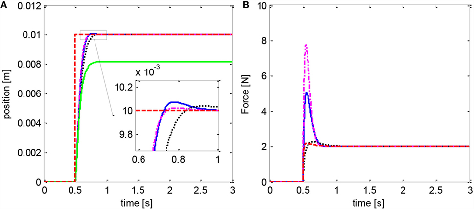
Figure 4. Adaptive controller (Eq. 16): step response (A); disturbance estimate (B). The baseline controller (Eq. 9) fails to reach the setpoint in this case (green line). Blue curve refers to c3 = 30, dotted black to c3 = 10, and centerline magenta to c3 = 50. Reference position and force are in dashed red.
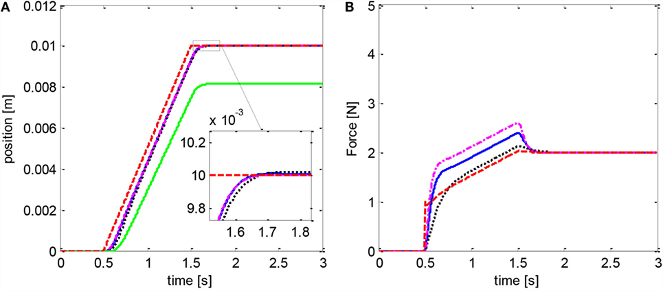
Figure 5. Adaptive controller (Eq. 16): ramp trajectory response (A); disturbance estimate (B). The baseline controller (Eq. 9) fails to reach the setpoint in this case (green line). Blue curve refers to c3 = 30, dotted black to c3 = 10, and centerline magenta to c3 = 50. Reference position and force are in dashed red.
The predictive control scheme (Eq. 25) was tested with null force d* = 0 and with a nominal input delay N = 20. This value is representative of the delay introduced by long supply lines used to power a pneumatic actuator (Yang et al., 2011; Franco et al., 2016). The results show that the predictive control achieves a smooth movement of the actuator (Figure 6). Instead, the baseline controller (Eq. 9) with the original tuning results in oscillations in the step response. Nevertheless, the settling time, the rise time, and the RMSE are larger with the predictive control (Eq. 25) compared to the reference condition. Consequently, the downside of the predictive control is a lower responsiveness. The performance of the baseline controller (Eq. 9) improves if the parameter c1 is tuned considering the input delay (c1 < 1/3NT = 15) and becomes similar to that of the predictive control (Eq. 25). Similarly, a larger delay demands a smaller value of c1 which results in lower responsiveness.
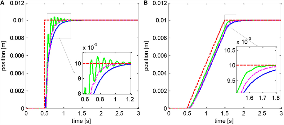
Figure 6. Predictive controller (Eq. 25): step response (A); ramp trajectory (B). The blue line represents the predictive controller. The green solid line represents the baseline controller (Eq. 9) with the original tuning (c1 = 25), while the magenta centerline refers to the baseline controller with the new tuning (c1 = 15). The reference position is in dashed red.
The new adaptive-predictive controller (Eq. 36), representing the main contribution of this work, was then evaluated considering a disturbance d = 1 + 100x1 + 10x2 and an input delay N = 20. The step response is depicted in Figure 7 while the ramp is in Figure 8. The settling time, the rise time, and the overshoot are larger than in the reference condition but smaller compared to the predictive control alone, due to the action of the adaptive algorithm. Tests with larger values of c3 show more pronounced oscillations and suggest that a more gradual estimate of the disturbance can be preferable in the presence of input delay. In this scenario, the controller (Eq. 25) shows a noticeable steady-state error. The controller (Eq. 16) becomes unstable with either c1 = 25 or c1 = 15 and c3 = 30. Setting c1 = 15 and c3 = 10 in Eq. 16 results in a controlled movement but in a larger tracking error [RMSE = 0.77 mm instead of RMSE = 0.65 mm with (Eq. 36)].
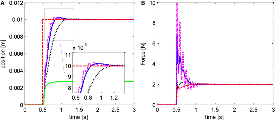
Figure 7. Adaptive-predictive controller (Eq. 36): step response (A); disturbance estimate (B). Blue curve refers to c3 = 30, dotted black to c3 = 10, and centerline magenta to c3 = 50. The adaptive controller (Eq. 16) becomes unstable in this case, while the predictive controller (Eq. 25) fails to reach the setpoint (green line). Reference position and force are in dashed red.
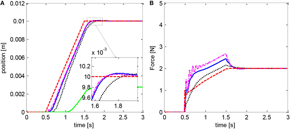
Figure 8. Adaptive-predictive controller (Eq. 36): response to ramp trajectory (A); disturbance estimate (B). Blue curve refers to c3 = 30, dotted black to c3 = 10, and centerline magenta to c3 = 50. The adaptive controller (Eq. 16) becomes unstable in this case, while the predictive controller (Eq. 25) fails to reach the setpoint (green line). Reference position and force are in dashed red.
An additional case was considered for the adaptive-predictive controller (Eq. 36) in order to test its robustness. The ramp trajectory was tested with a larger disturbance including a discontinuous square-wave component [d′ = 1 + 200x1 + 10x2 + 0.1sign(sin(πt))] and with a variable input delay corresponding to a random number between 1 and N (Figure 9). Even in this case, the adaptive-predictive algorithm (Eq. 36) achieves an acceptable tracking accuracy (RMSE = 0.74 mm) considering that the disturbance is larger than in previous simulations, therefore demonstrating remarkable robustness. Finally, the performance of Eq. 36 remains superior to that of (Eq. 16) (RMSE = 0.85 mm with c1 = 15, c3 = 10).
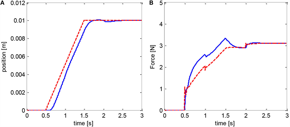
Figure 9. Adaptive-predictive controller (Eq. 36): response to ramp trajectory with larger disturbance including a discontinuous square-wave component, and with randomly variable input delay (A); corresponding disturbance estimate (B). The red dashed line represents the reference, while the blue lines represent the recorded position and the force estimate.
This paper presented a discrete-time control scheme that combines adaptive and predictive algorithms for a system subject to force disturbance and input delay. The controller is expressed in a discrete-time recursive form and, differently from Karafyllis and Krstic (2013), it does not rely on the assumption of bounded disturbances. This is particularly beneficial in unstructured environments, such as percutaneous intervention. Differently from Pyrkin and Bobtsov (2015), the algorithm is applicable to non-linear systems and considers a generic additive disturbance. The stability and convergence of the system to the target dynamics was analyzed discussing the effects of the input delay and of the disturbance, and expressing criteria for the parameter selection.
The simulations show that the adaptive disturbance estimation is essential for compliant actuators in order to achieve high tracking accuracy in the presence of a force disturbance. In the controller design, the disturbance was assumed independent on the system states and constant over the input delay τ. The simulations suggest that the control scheme is also effective for variable disturbances, which could be either due to external forces or that might originate as an effect of model uncertainty. Furthermore, the simulations show that the predictive control scheme (Eq. 25) is effective in reducing the oscillations that would occur in the presence of input delay. This behavior is particularly desirable in the case of teleoperated percutaneous intervention, since oscillations in the actuator position are transferred to the needle insertion force and are then reflected on the operator, degrading the haptic feedback. Notably, tuning the baseline controller for a more damped response can achieve a similar effect to the predictive controller. In both cases, a larger input delay demands a less aggressive control action that results in lower responsiveness and larger tracking error.
The simultaneous presence of disturbance and input delay was addressed with the adaptive-predictive controller (Eq. 36). In this scenario, the adaptive control scheme (Eq. 16) with the original tuning can result in oscillations and instability. This result confirms the conclusions of Karafyllis and Krstic (2013), indicating that parameter uncertainty can have larger effects on the system performance in the presence of input delay. Conversely, the adaptive-predictive controller achieves a satisfactory step response and tracking performance. In general, the simulations indicate that a larger input delay could benefit from a more gradual estimate of the disturbance, while an aggressive tuning results in oscillations and can be detrimental to the performance. Finally, the results show that the adaptive-predictive controller is also effective for a variable discontinuous disturbance and a randomly variable input delay, which is a realistic operating condition for teleoperated percutaneous intervention.
Future work will investigate the adaptive compensation of an unknown input delay. Additionally, an automatic tuning procedure for the controller parameters will be explored. Furthermore, more elaborated models of the interaction forces will be considered. Finally, the adaptive-predictive control algorithm will be implemented on a prototype and will be validated with experiments.
The first author was responsible for the conception of the work, the data analysis and interpretation, drafting the article, reviewing it, and approving the version to be published.
The author declares that the research was conducted in the absence of any commercial or financial relationships that could be construed as a potential conflict of interest.
The reviewer YC and handling Editor declared their shared affiliation, and the handling Editor states that the process nevertheless met the standards of a fair and objective review.
The author is grateful to Prof. Alessandro Astolfi for the several stimulating discussions on control theory.
Astolfi, A., Karagiannis, D., and Ortega, R. (2008). Towards applied nonlinear adaptive control. Annu. Rev. Control 32, 136–148. doi: 10.1016/j.arcontrol.2008.08.003
Comber, D. B., Slightam, J. E., Gervasi, V. R., Neimat, J. S., and Barth, E. J. (2016). Design, additive manufacture, and control of a pneumatic MR-compatible needle driver. IEEE Trans. Robot. 32, 138–149. doi:10.1109/TRO.2015.2504981
Franco, E., Brujic, D., Rea, M., Gedroyc, W. M., and Ristic, M. (2016). Needle-guiding robot for laser ablation of liver tumors under MRI guidance. IEEE/ASME Trans. Mechatron. 21, 931–944. doi:10.1109/TMECH.2015.2476556
Franco, E., and Ristic, M. (2015). “Adaptive control of a master-slave system for teleoperated needle insertion under MRI-guidance,” in 2015 23rd Mediterranean Conference on Control and Automation (MED) (Torremolinos: IEEE), 61–67.
Gerboni, G., Ranzani, T., Diodato, A., Ciuti, G., Cianchetti, M., and Menciassi, A. (2015). Modular soft mechatronic manipulator for minimally invasive surgery (MIS): overall architecture and development of a fully integrated soft module. Meccanica 50, 2865–2878. doi:10.1007/s11012-015-0267-0
Iranpanah, B., Chen, M., Patriciu, A., and Sirouspour, S. (2015). A pneumatically actuated target stabilization device for MRI-guided breast biopsy. IEEE/ASME Trans. Mechatron. 20, 1288–1300. doi:10.1109/TMECH.2014.2341657
Karafyllis, I., and Krstic, M. (2013). Robust predictor feedback for discrete-time systems with input delays. Int. J. Control 86, 1652–1663. doi:10.1080/00207179.2013.792005
Krstic, M. (2010). Input delay compensation for forward complete and strict-feedforward nonlinear systems. IEEE Trans. Automat. Contr. 55, 287–303. doi:10.1109/TAC.2009.2034923
Krstic, M., Kanellakopoulos, I., and Kokotovic, P. (1995). Nonlinear and Adaptive Control Design. Wiley. Available at: http://www.worldcat.org/title/nonlinear-and-adaptive-control-design/oclc/32166728?referer=di&ht=edition
Li, G., Su, H., Cole, G., Shang, W., Harrington, K., Camilo, A., et al. (2014). Robotic system for MRI-guided stereotactic neurosurgery. IEEE Trans. Biomed. Eng. 62, 1077–1088. doi:10.1109/TBME.2014.2367233
Melzer, A., Gutmann, B., Remmele, T., Wolf, R., Lukoscheck, A., Bock, M., et al. (2008). INNOMOTION for percutaneous image-guided interventions. Eng. Med. Biol. Mag. 27, 66–73. doi:10.1109/EMB.2007.910274
Monaco, S., and Normand-Cyrot, D. (2015). “Immersion and invariance in delayed input sampled-data stabilization,” in 2015 European Control Conference (ECC) (Linz: IEEE), 169–174.
Pan, Y.-J., Gu, J., and Chen, Z. (2014). Adaptive robust control of bilateral teleoperation systems with unmeasurable environmental force and arbitrary time delays. IET Control Theory Appl. 8, 1456–1464. doi:10.1049/iet-cta.2014.0179
Pyrkin, A., and Bobtsov, A. (2015). Adaptive controller for linear system with input delay and output disturbance. IEEE Trans. Automat. Contr. PP, 1. doi:10.1109/TAC.2015.2509428
Slotine, J.-J. E., and Li, W. (1991). in Applied Nonlinear Control, ed. J. Wenzel (Englewood Cliffs: Prentice Hall).
Stoianovici, D., Kim, C., Srimathveeravalli, G., Sebrecht, P., Petrisor, D., Coleman, J., et al. (2014). MRI-safe robot for endorectal prostate biopsy. IEEE/ASME Trans. Mechatron. 19, 1289–1299. doi:10.1109/TMECH.2013.2279775
Tse, Z. T. H., Elhawary, H., Rea, M., Davies, B., Young, I., and Lamperth, M. (2012). Haptic needle unit for MR-guided biopsy and its control. IEEE/ASME Trans. Mechatron. 17, 183–187. doi:10.1109/TMECH.2011.2113187
van Gerwen, D. J., Dankelman, J., and van den Dobbelsteen, J. J. (2012). Needle-tissue interaction forces – a survey of experimental data. Med. Eng. Phys. 34, 665–680. doi:10.1016/j.medengphy.2012.04.007
Yalcin, Y., and Astolfi, A. (2011). “Discrete time immersion and invariance adaptive control for systems in strict feedback form,” in IEEE Conference on Decision and Control and European Control Conference (Orlando: IEEE), 343–347.
Yalçin, Y., and Astolfi, A. (2012). Immersion and invariance adaptive control for discrete time systems in strict feedback form. Syst. Control Lett. 61, 1132–1137. doi:10.1016/j.sysconle.2012.09.010
Yang, B., Roys, S., Tan, U.-X., Philip, M., Richard, H., Gullapalli, R., et al. (2014). Design, development, and evaluation of a master-slave surgical system for breast biopsy under continuous MRI. Int. J. Rob. Res. 33, 616–630. doi:10.1177/0278364913500365
Yang, B., Tan, U. X., McMillan, A., Gullapalli, R., and Desai, J. P. (2011). Design and control of a 1-DOF MRI compatible pneumatically actuated robot with long transmission lines. IEEE ASME Trans. Mechatron. 16, 1040–1048. doi:10.1109/tmech.2010.2071393
Keywords: teleoperation, adaptive control, predictive control, input delay, discrete-time
Citation: Franco E (2016) Combined Adaptive and Predictive Control for a Teleoperation System with Force Disturbance and Input Delay. Front. Robot. AI 3:48. doi: 10.3389/frobt.2016.00048
Received: 25 April 2016; Accepted: 28 July 2016;
Published: 10 August 2016
Edited by:
Ka-Wai Kwok, University of Hong Kong, Hong KongReviewed by:
Yue Chen, University of Hong Kong, Hong KongCopyright: © 2016 Franco. This is an open-access article distributed under the terms of the Creative Commons Attribution License (CC BY). The use, distribution or reproduction in other forums is permitted, provided the original author(s) or licensor are credited and that the original publication in this journal is cited, in accordance with accepted academic practice. No use, distribution or reproduction is permitted which does not comply with these terms.
*Correspondence: Enrico Franco, ZWYxMzExQGltcGVyaWFsLmFjLnVr
Disclaimer: All claims expressed in this article are solely those of the authors and do not necessarily represent those of their affiliated organizations, or those of the publisher, the editors and the reviewers. Any product that may be evaluated in this article or claim that may be made by its manufacturer is not guaranteed or endorsed by the publisher.
Research integrity at Frontiers

Learn more about the work of our research integrity team to safeguard the quality of each article we publish.