- 1Simulation, Systems Optimization and Robotics Group, Department of Computer Science, Technische Universität Darmstadt, Darmstadt, Germany
- 2Capable Humanitarian Robotics and Intelligent Systems Laboratory, Department of Physics, Computer Science and Engineering, Christopher Newport University, Newport News, VA, USA
While recent advances in approaches for control of humanoid robot systems show promising results, consideration of fully integrated humanoid systems for solving complex tasks, such as disaster response, has only recently gained focus. In this paper, a software framework for humanoid disaster response robots is introduced. It provides newcomers as well as experienced researchers in humanoid robotics a comprehensive system comprising open source packages for locomotion, manipulation, perception, world modeling, behavior control, and operator interaction. The system uses the Robot Operating System (ROS) as a middleware, which has emerged as a de facto standard in robotics research in recent years. The described architecture and components allow for flexible interaction between operator(s) and robot from teleoperation to remotely supervised autonomous operation while considering bandwidth constraints. The components are self-contained and can be used either in combination with others or standalone. They have been developed and evaluated during participation in the DARPA Robotics Challenge, and their use for different tasks and parts of this competition are described.
1. Introduction
The 2015 DARPA Robotics Challenge (DRC) Finals showed that robotic systems provide promising capabilities for providing assistance in disaster scenarios that necessitate complex locomotion and manipulation abilities (see Figure 1). At the same time, the competition showed that there are still numerous research challenges that have to be solved before robot systems are capable and robust enough for use in real disasters.
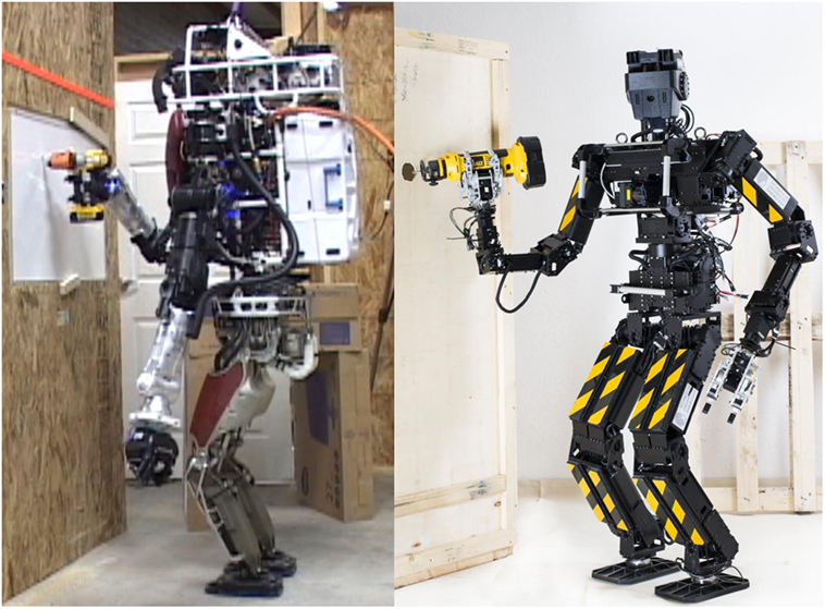
Figure 1. Two of the robot systems used. The Boston Dynamics Inc. (BDI) Atlas robot and the Robotics THOR-MANG robot.
Toward this goal, we present our ROS-based framework for solving complex locomotion and manipulation tasks. To our knowledge, it is the first fully open-sourced framework featuring documentation that allows other researchers to replicate the provided functionality and results in simulation or, after necessary interfacing, on their own robot systems. Our framework is based on ROS (Quigley et al., 2009), which has evolved to be the de facto standard robotics middleware within the robotics research community and parts of the robotics industry.
The contribution of this work is twofold:
• The framework and architecture of our approach for enabling complex humanoid robots to fulfill challenging tasks in disaster environments are detailed.
• We provide a detailed discussion of different components for perception, locomotion, and manipulation contributing to achieve the overall task of flexible disaster response.
2. Related Work
While humanoid robotics is an active research area, the DRC program demonstrated the wealth of open research challenges in areas, such as controls, planning, and human–robot interaction. For the first time, humanoids had to fulfill a variety of tasks in a common competition setup, which shifted focus from concentration on specialized research topics toward the realization of humanoid (and other) systems that provide integrated perception, locomotion, and manipulation capabilities.
After the DRC Trials, publications by multiple teams described their approaches, but the majority of teams did not make their software available as open source that would allow for reproduction of the presented results. The MIT DRC team uses optimization-based planning and control (Fallon et al., 2015), LCM (Huang et al., 2010) as a middleware, and the Matlab-based Drake system as a planning and control backend.1 Team IHMC uses a proprietary middleware based on Java (Johnson et al., 2015). Both teams provide significant parts of their software as open source software, but do not provide instructions and a setup that allows running their full setup as used for the DRC in simulation. We provide an overview of our DRC related research in Kohlbrecher et al. (2015) and detail aspects in separate publications on footstep planning (Stumpf et al., 2014), manipulation (Romay et al., 2014, 2015), and behavior control (Schillinger et al., 2016).
In Du et al. (2014), a manipulation approach used with the BDI Atlas robot is described, focusing on some of the DRC tasks. In Banerjee et al. (2015) another human-supervised manipulation control approach is described with a focus on the door DRC task.
For manipulation, bilateral teleoperation approaches allow teleoperation by the operator, while the robot simultaneously provides force feedback. Although demonstrations show the approach to be highly promising where applicable, there are potential stability issues when using bilateral approaches (Willaert et al., 2012) that make their use infeasible with constrained and significantly varying communications conditions, such as those considered in this work.
A relevant account by various teams of “What happened at the DRC” is available online (DRC-Teams, 2015). This gives a brief summary of issues and results from many teams.
3. Architecture
The goal of this work is to provide a comprehensive and re-usable software ecosystem to enable humanoid robot systems to perform complex locomotion and manipulation tasks. To provide compatibility with a wide range of robot systems and to reduce integration effort with existing open source software, the system uses ROS as middleware.
3.1. Requirements
The ability to leverage existing developments and software in a way that allows users to avoid the duplication of efforts and spending time re-implementing approaches is highly relevant for advancing the field of robotics research. While this requirement is not as relevant for mature commercialized robotic systems, using standard software for functional system components allows new users to reproduce results quickly. This is major driver for accelerating research in robotics and, thus, a key factor for accelerating the development of disaster response robots; that is, developing supervised autonomous systems that are deployable in real disaster situations.
The achievable complexity of robotic system architectures is limited unless the architectural design allows a transparent exchange of functional components (e.g., for manipulation or footstep planning) and also can be extended by additional functional components. Modularity, re-usability, and extensibility are key properties of the architectural design needed to enable sustainable robotic system development.
While robots can be considered expendable in the sense that a loss is acceptable (in contrast to human responders), high reliability and resilience are important aspects that disaster response robotic systems have to provide. Failures in disaster situations can have grave consequences; for instance, when a robot gets stuck or otherwise unresponsive, it can then block future access for responders, or tie up responders that could be required elsewhere.
As communications in disaster environments can be degraded, the possibility of delayed, reduced bandwidth, intermittent, or even completely absent communication has to be considered in the system design. Appropriate measures have to be taken to be tolerant of variations in communication link quality. This also motivates the need for autonomous capabilities. Autonomous performance under ideal (communications) conditions might actually be inferior to a human expert using teleoperation; however, under constrained communication conditions with outages or very high latencies, teleoperation might become impossible to use. In that case, leveraging autonomous functionality, for instance, for motion planning and control, is the only possible way to proceed.
3.2. System Architecture
To achieve high reliability, as discussed for the coactive design concept (Johnson et al., 2014) observability, predictability, and directability of the robotic system are required. When considering the human supervisor and robot as a team, the members, thus, have to allow each other to understand the state of the other side (observability). They also have to be able to predict and understand the intent of the other side (predictability). Lastly, team members have to be able to communicate meaningful and accurate commands (directability).
The capability of informing the operator about the robot state using appropriate information and visualization must be considered (Kohlbrecher et al., 2015). Predictability is achieved by visualizing action outcomes prior to the command being sent to the robot. Achieving directability requires interfaces that allow for efficient and reliable interaction. These concepts will be revisited in following sections.
As noted previously, to achieve high reliability and versatility, the capability to flexibly change control and interaction modes between autonomous and teleoperated operation is crucial. While autonomous and assistive functions promise to reduce workload of operators and in some cases higher reliability, they can be brittle in real-world scenarios, where unexpected situations and failures can foil prior mission plans. In such cases, the capability of flexible switching between modes can significantly improve the reliability of the system, as the human supervisor has a toolbox of options at her disposal and can dynamically switch between them, adapting to the situation.
As the lowest level of interaction between operator and robot, teleoperation should always be available, communication permitting. Bypassing autonomous functions, this interaction mode shifts burden to the operator. Importantly, connectivity between robot and operator has to be sufficient in both directions; otherwise teleoperation becomes slow, unsafe, or even impossible.
With currently fielded robotic systems, these good communications conditions have to be met, as otherwise the robot becomes inoperable. Once autonomous assistance functionality is in more widespread use, the capability to fall back to teleoperation can be impeded by communication constraints, allowing for new applications. As teleoperation is the last fallback mode in case autonomous components fail, availability of it, no matter how limited, is important for overall reliability as it provides the ability to recover from unexpected scenarios.
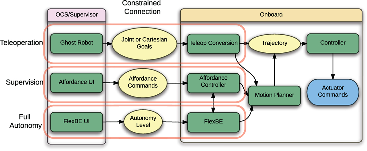
In supervised autonomy mode, the operator provides task-level goals to the robot that are then followed autonomously using onboard systems. The operator observes actions, and generally provides permission to proceed at significant steps. This reduces reliance on connectivity and low latency communication, as the robotic system can follow task-level goals even when communication is intermittent; however, such an approach requires sophisticated sensing and planning capabilities for onboard systems. Using full autonomy, the human operator only specifies the mission and associated tasks and provides a start command, monitors data provided by the robot to maintain situation awareness, and either reacts to requests from the robot or switches to a lower autonomy mode on her own discretion. The clear advantage of full autonomy is that there is no need for communications as long as everything works well. The onboard autonomy system leverages the capabilities for task-solving used in the supervised autonomy mode and also makes use of planning capabilities, either directly or via task-level autonomy functionality.
It is crucial that when using a flexible level of interaction, the system stays in a well-defined state. For instance, when teleoperation commands are sent, autonomous control components have to be notified of the switch in interaction level as to not cause undefined behavior when commands both from the operator and autonomous executive are executed at the same time. This is discussed in Section 6.
3.3. Middleware
Developing a modular system requires a common communication framework, or middleware. To satisfy the research-level requirements on reproducibility and modularity, ROS is chosen as the underlying middleware. The nearly ubiquitous proliferation of ROS in the research community allows for using established standard interfaces and the ROS infrastructure allows for the development of highly modular code. With a large user base, the barrier of entry for other researchers to use open source developments is much lower, which is highly advantageous considering the goal of advancing research for challenging applications, such as versatile disaster response robots.
While ROS provides solutions for many common robotics tasks, there are capabilities that received less attention by the research community than others. This is also true for disaster response using humanoid robots. The following areas were identified as requiring significant contributions to enable robot to perform complex disaster response tasks:
• Communication over constrained connections. ROS does not provide built-in facilities for communication over a degraded link.
• Footstep planning for locomotion in challenging terrain.
• Operator guided manipulation.
In the remainder of this work, components that address these shortcomings are detailed. It should be noted that the focus is not on low-level control of humanoid robots; it is assumed that basic control and locomotion capabilities are provided. The presented contributions leverage and interface with these basic control capabilities to achieve flexible high-level control.
3.4. Constrained Communications
While ROS provides transparent capability for distributing components over different machines by means of the network-based TCP/IP-based transport, communication constraints can impose additional challenges that make using ROS standard transports not feasible in some highly constrained scenarios. For those, specialized communication bridge tools need to be used, separating the ROS networks of the onboard and operator control station OCS sides. Such software has been developed by Team ViGIR during participation in the DRC (Kohlbrecher et al., 2015). In the sections that follow, we reference communications across the comms bridge; therefore, this section provides a basic description of the functionality.
The ROS middleware presumes a connection to a centralized communications manager (ROS master). Furthermore, communication with the ROS master requires a non-trivial amount of communication as modules come on line. As the degraded communications allowed by the DRC rules did not permit such unrestricted communications, Team ViGIR used a dual master setup between the OCS side and the robot onboard side.
The communication bridge system (comms bridge) developed by Team ViGIR uses mirrored components on either side that pass data across dedicated network channels. The components subscribe to messages on one side, compress them using custom encodings, send them across to the other side for uncompressing, and republish them as standard ROS messages. The messages use consistent names on each side to allow the system to also run transparently as a single ROS network without the comms bridge.
As the communication channels and compression are optimized for the specific rules of the DRC, and contain certain proprietary data for the Atlas robot, we have not open sourced the comms bridge and, therefore, it is not the focus of this paper. The general idea of a comms bridge is generally applicable, so that this paper describes several of the approaches to data communication over constrained links in the sections that follow.
4. Perception and State Estimation
The worldmodel system has to provide state estimation and situational awareness (SA) to the supervisor–robot team. To effectively leverage the human supervisor’s cognitive and decision-making capabilities, a state estimate of both the internal and external state of the system has to be made available via the often constrained communication link between robot and operator. With current state of the art sensors often providing sensor data at rates in excess of 100 MB/s, this is both crucial and challenging.
The type of communication constraints under which the perception system has to work depends on used hardware and encountered scenario. They can include limited bandwidth, significant latency, and intermittent communication outages. The worldmodel system is designed to provide situational awareness and state estimation for the operator under all of these conditions. To achieve reliable and efficient manipulation with a remote operator in the loop, obtaining 3D geometry data is crucial. In the following sections, the approach and components for providing SA to both human supervisors and the robot are described.
4.1. Worldmodel Server
The worldmodel server2 component preprocesses, collects, and aggregates sensor data and makes it available to both onboard and OCS system components. Leveraging established open source libraries, such as PCL (Rusu and Cousins, 2011) and octomap (Hornung et al., 2013), the worldmodel server allows queries of information about the environment with flexible level of detail and bandwidth consumption.
Three-dimensional sensing is provided by onboard sensors, providing point cloud data. A frequently used setup used here is a LIDAR and optionally a RGB-D type camera system. As RGB-D sensing generally has a smaller field of view, is sensitive to lighting conditions, and has less consistent measurement accuracy, LIDAR data are used as the default main source for creating a 3D geometry model of the environment onboard the robot. To achieve this, the planar scans of the LIDAR have to be preprocessed and aggregated, so full 3D point clouds can be generated from them. The following preprocessing steps are employed:
First, scan data are filtered for spurious measurements commonly called “mixed pixels” that occur at depth discontinuities (Tuley et al., 2005; Tang et al., 2007), using the shadow point filter available as a ROS package.
The filtered scan is then converted to a point cloud representation. During this process, motion of the LIDAR on the relative to the robot is considered and a high fidelity projection is employed, transforming every scan endpoint separately.
In a last step, parts belonging to the robot have to be filtered out of LIDAR data. To increase robustness against errors in kinematics calibration, a specialized robot geometry model uses simplified and enlarged collision geometries for self-filtering purposes.
LIDAR scans are saved in a ring buffer along with snapshots of coordinate frames used within the system. By employing this method, aggregate point clouds relative to different coordinate frames can be provided on request. A ROS API allows querying the world model via both ROS topics or services and flexibly retrieving region of interest point cloud or octomap data relative to different coordinate frames. This capability can be employed by both onboard and OCS system components.
The primary onboard 3D geometry model is created using octomap, a volumetric, probabilistic approach using an octree as a back-end. Using this approach, the environment representation maintained onboard can be updated efficiently and in a probabilistically sound way. Even in case of changes in the environment or drift in state estimation, the environment model is updated accordingly and maintains a useful representation. The octomap environment model provides the main geometry representation and is used for multiple purposes. Using ray casting, distances to geometry can easily be determined. This feature can be used from within the OCS to perform ray cast distance queries against onboard geometry. In this case, only the ray cast information has to be transmitted to the robot and the distance information is transmitted back, utilizing only very low bandwidth.
The capability to request ROI data of the environment model allows to transfer small ROI geometry over the constrained connection on supervisor demand and also makes geometry available to other modules on request, like the footstep planning system. Similarly, it is possible to request 2D grid map slices of the octomap representation, aggregating 3D data into a 2D grid map. Using compression during transmission, this representation is very compact and often sufficient for supervisors to gain SA.
4.2. LIDAR Data Compression
In case of intermittent communication, the approach for querying the onboard worldmodel for data from the OCS as described in the previous section can fail, as no data can be transmitted in periods of communication loss. Instead, it is desirable to transmit all geometry information available onboard to the OCS side as long as a communication window is available. A mirror of the worldmodel can then be queried on the OCS side instead of relying on a connection to the remote onboard worldmodel. The approach described in the following is available online.3
In case of intermittent communication between supervisors and robot, two instances of the worldmodel server are used: one for the onboard/robot side and one for the OCS side. As direct transmission of point cloud data is error prone when experiencing packet loss, additional processing on LIDAR data is performed to make each packet compact enough to fit within a standard 1500-B UDP packet and compress it as to be able to transmit a maximum of data during a communications burst.
For compression of LIDAR data, the GIS research community developed solutions for large-scale airborne LIDAR datasets (Isenburg, 2013), but these significantly differ in structure from those by small planar scanners. For this reason, an approach leveraging the special structure of data provided by planar scanners is presented here.
Direct transmission of point cloud data generated onboard the robot would cause prohibitive bandwidth cost as a point cloud representation with at least three floating point values for each Cartesian point is not a compact one. For this reason, the natural and compact representation of a laser scan as an array of range values is leveraged and used instead. To fully reconstruct the 3D geometry captured by a single scan, a high fidelity projection of the scan has to be performed, however, taking into account motion of the LIDAR mirror during the data capture process. If this motion is not considered, scan data show visible skew and ghosting (double walls) once it gets converted to a point cloud representation. The following approach is thus utilized:
• Perform a 3D high fidelity projection onboard the robot and perform self-filtering. The onboard octomap and worldmodel are updated simultaneously.
• Compress the scan data by writing the range values to a 2-Byte array representing millimeters and also encoding self-filtering information. Threshold and map intensity information to a single Byte.
• Add information about the scanner transform in world frame, one transform for the start of the scan and one for the end. This information allows performing a high fidelity projection of the scan after unpacking on the OCS side.
• Split the compressed scan into chunks that are small enough to be compressible to <1500 B. A schematic of this approach is available in Figure 2. By using this approach, each compressed scan packet is a self-contained unit and can be unpacked and used on the receiver side without the need for packet reassembly.
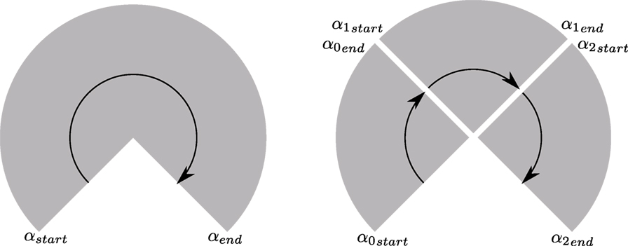
Figure 2. Splitting LIDAR scans for compression. A schematic view from the top is shown here and the rotation direction indicated by an arrow. A LIDAR scan can be described by the start angle αstar and end angle αend. With a known angular resolution, scan points can be projected. To achieve a small packet size, the scan is split and intermediate start and end angles computed.
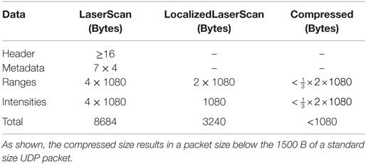
On the OCS side, the compression process is reversed, and resulting scan data are used to update the OCS world model. The size of a LaserScan message is dominated by the range and intensity fields. A typical Hokuyo LIDAR, for instance, provides 1080 measurements per scan. For compression, floating point range values in meters are converted to millimeters and stored in an unsigned 16 bit number. Self-filtering of robot parts from LIDAR data requires knowledge of the whole transform tree of the robot and, thus, has to be performed on the onboard side if transmission of high bandwidth transform data to the OCS side is to be avoided. Per default, self-filtering is, thus, performed onboard and compressed laser scan data are annotated with a single bit per scan point, indicating if the self-filter determined that it belongs to the robot or objects attached to the robot.
Intensity data are converted from a floating point intensity to an unsigned 8 bit number. Here, a loss in fidelity is acceptable as intensity is mainly used for visualization and a range of 28 values is sufficient for presentation to the human supervisors.
Table 1 shows the different scan representation and their relative size. In Figure 3, the setup using one worldmodel instance each on the onboard and OCS sides is visualized. The synchronization is performed using the previously described compressed scan transmission mechanism.
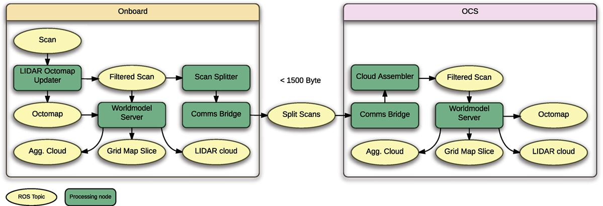
Figure 3. Overview of the Worldmodel server setup. Worldmodel information is synchronized via compressed LIDAR data. One instance of the worldmodel server is running on the onboard and OCS side each.
4.3. Sensor Data Processing for Situation Awareness
To provide the supervisor(s) with the necessary SA for complex manipulation tasks, not only geometry but also image and texture data are crucial. In this section, components allowing for the processing of sensor data to achieve suitable representations and visualizations for obtaining supervisor SA are discussed.
4.3.1. Region of Interest Image Data
As images are readily compressible using standard compression methods, providing such data to the operator is often possible and can be feasible even when bandwidth is constrained. Often, only a limited region of interest in the full image is required. Examples are visually inspecting the quality of a grasp or the accuracy of end-effector positioning. To provide this capability, the operator can request full image and region of interest independently, making it possible to show coarse resolution full images, but high-resolution regions of interest. To minimize communication requirements, an optional video frame-rate is part of the request and images can be sent at a fixed rate without need for bi-directional communication.
4.3.2. Mesh Generation
To provide a high fidelity visualization for 3D geometry data, an infrastructure for generating meshes from both LIDAR point clouds and camera or LIDAR-based depth images was developed.4 Compared to plain point cloud visualization, this approach allows for a clear view of geometry and texturing of mesh surfaces, which allows for easier scene understanding by human supervisors.
Figure 4 shows a schematic of the mesh generation data flow. As indicated by the light blue OR gates, the mesh generation process can be based on different kinds of input data. Based on depth images, a mesh can be generated using a FastMesh (Holz and Behnke, 2013) approach. The depth image can either be provided by a RGB-D type camera or it can be generated from LIDAR data. In the latter case, data have to be aggregated over time, however. Instead of depth images, LIDAR-based point clouds can also be used for mesh generation; in this case, the mesh is generated from LIDAR point cloud data directly. This approach does not have the restricted field of view of the depth image-based one.
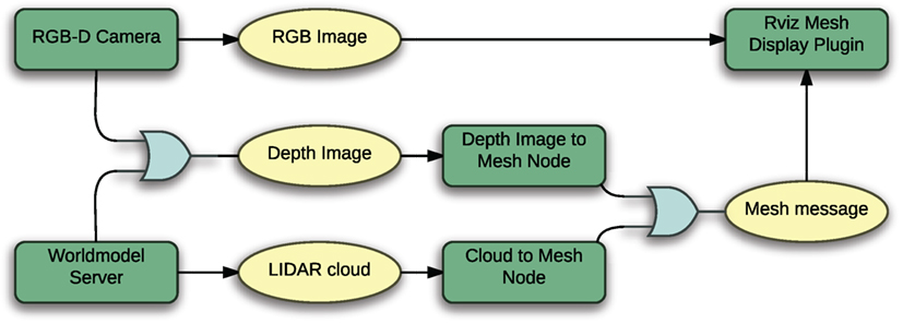
Figure 4. Options for generating a mesh representation of the environment. The RGB camera image gets texture mapped on a mesh generated from LIDAR or depth image data. The depth image is either provided by a camera directly or can be generated from aggregated LIDAR point cloud data.
An example of generating meshes based on stereo camera RGB and depth data is shown in Figure 5. Three novel rendered viewpoints are shown, demonstrating how the approach combines the fidelity of image data with 3D geometry.
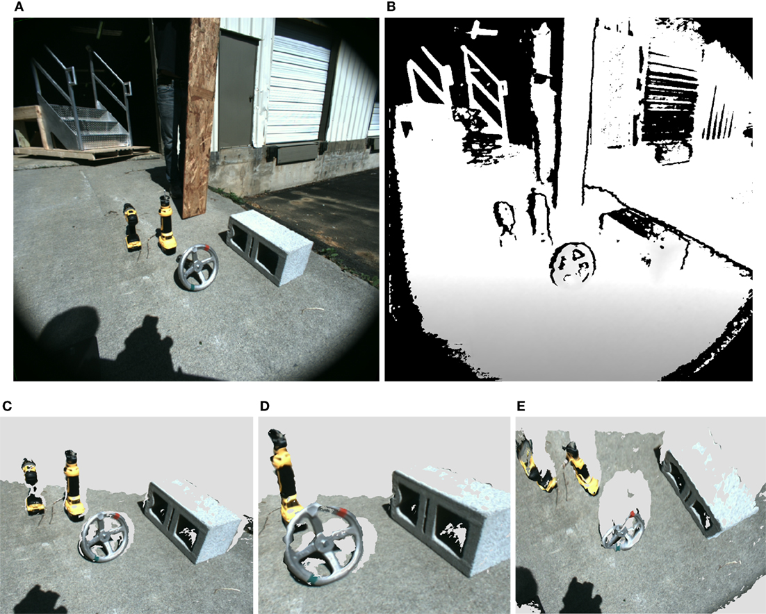
Figure 5. Rendering novel views based on textured mesh data. (A) RGB image, (B) depth image, and (C–E) novel view points rendered based on applying texture to a mesh generated from the depth image.
4.3.3. Fisheye Camera
The Atlas robot could not rotate the Multisense sensor head around the yaw axis, greatly limiting the field of view of the main sensor system. With early versions of the Atlas robot, this was a severe issue, as the volume of good manipulability for the arms was outside the Multisense sensor field of view. To remedy this issue, a system for rectification the Fisheye lenses of the fisheye cameras was developed.5 Using a ROS-integrated version of the OCamLib library (Scaramuzza and Siegwart, 2007), the fisheye distortion is calibrated. This allows generating novel rectified views from fisheye images not exhibiting severe distortion that otherwise makes judging of spatial relations difficult for operators.
Recomputing the rectification online, the system can track arbitrary frames on the robot or in the environment. It is, thus, possible to create a virtual pinhole camera that, for instance, tracks an end effector of the robot.
5. Planning
For manipulation, motions to move manipulators into desired configurations for grasping or other tasks need to be generated. As it can reduce operator workload considerably, a crucial capability is automated collision avoidance, both considering self-collisions of the robot (e.g., arm coming in contact with torso) and collision of robot parts with the environment. When performing manipulation in contact with the environment, motion must not lead to unplanned high internal forces acting on the robot, as these can quickly lead to damage to the robot, especially if it loses balance as a result. While force or admittance control approaches can reduce this risk, they are often difficult to implement due to limited force sensing and control performance on real systems. Preventing unintended contact in the first place thus serves as a risk reduction measure.
As high latency limits the usefulness of otherwise promising approaches for teleoperation of end effectors that rely on real-time feedback (Leeper et al., 2013), direct control is not feasible. Instead, the supervisor(s) specify goal joint configurations or Cartesian goal poses and requests robot onboard systems to reach them.
The system described in this section is available as open source.6
5.1. Previewing Manipulation
As described in Chapter 4, the worldmodel server provides the supervisor(s) with the necessary tools to achieve situational awareness of the environment state in a variety of different bandwidth conditions. To be able to reliably perform manipulation, an approach for predictive visualization of how the robot interacts and likely will interact with the environment in the future is required.
With the high number of DOF of humanoid systems and the challenges of balance control, judging the reachability and manipulability of the robot for a given task can be much more difficult than for more conventional robots. While inverse reachability approaches show promising results in the literature (Vahrenkamp et al., 2013; Burget and Bennewitz, 2015), they do not consider constraints beyond kinematics and self collisions. Such additional constraints are for instance sensor visibility constraints or control-related constraints due to appendage control performing better in some configurations than others. It would be possible to incorporate those into inverse reachability analysis, but this remains a largely unsolved topic for research at this time.
To provide an intuitive interface to human operators, the so called “ghost robot” is used. This is a interactive puppet robot that can be used to predictively simulate the kinematics of manipulation tasks. The state of the ghost robot can be modified in the user interface without effects on the real robotic system. Once the supervisor is satisfied with ghost robot based planning, planning and motion requests can be generated based on the ghost robot state using variety of different options detailed below.
The ghost robot is an essential tool for teleoperation and supervised autonomy and is used for the full range of manipulation and locomotion control. While it remains possible to move the robot by sending joint angles directly, this is discouraged due to the high risk involved in such actions.
As shown in Figure 6 the ghost robot state can be modified based via a ROS API that allows for the following options:
• Joint angles. The ghost robot can externally be set to be in a desired joint angle configuration. Importantly, a subset of joints can be used here.
• Cartesian goals for end effectors. The ghost robot end effectors can be moved to Cartesian goals. In this case, an IK solver is used internally to solve for the joint positions.
• Cartesian goals for the robot pose. The ghost robot root frame (frequently the pelvis in case of a humanoid) can be moved to a desired Cartesian goal pose.
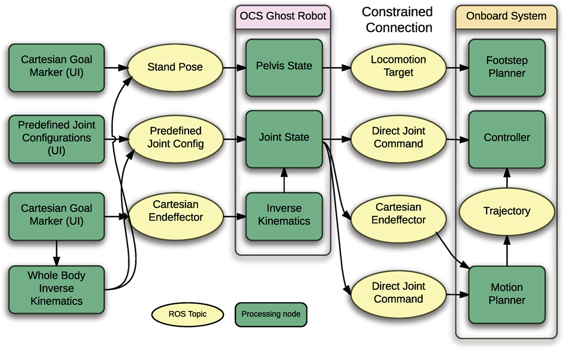
Figure 6. Schematic showing inputs and outputs for the ghost robot that is used for pre-planning manipulation tasks.
If a whole body IK solver is used externally, the ghost can also be set to a desired state by jointly using the joint angle and Cartesian robot pose interfaces simultaneously.
Based on the ghost robot state, the following types of commands can be generated to be executed on the real robot:
• A goal pose for the footstep planner based on the ghost robot pelvis position in the global frame.
• The joint configuration of one of the ghost’s appendage groups can be sent to the onboard controller as a motion target.
• The same joint configuration can be sent to the onboard motion planner, which then generates a collision free trajectory for it.
• The Cartesian end-effector pose can be sent to the onboard motion planner, which then generates a collision free trajectory to reach it.
It should be noted that the last two options are not equivalent on most humanoid robots, as balance control generally will shift the pelvis pose when the arm configuration of the robot changes, resulting in an offset for the first option.
Figure 7 shows use of the ghost robot during the DRC Trials. It is used for determining a stand pose for the robot on the left and for planning manipulation of a valve on the right.
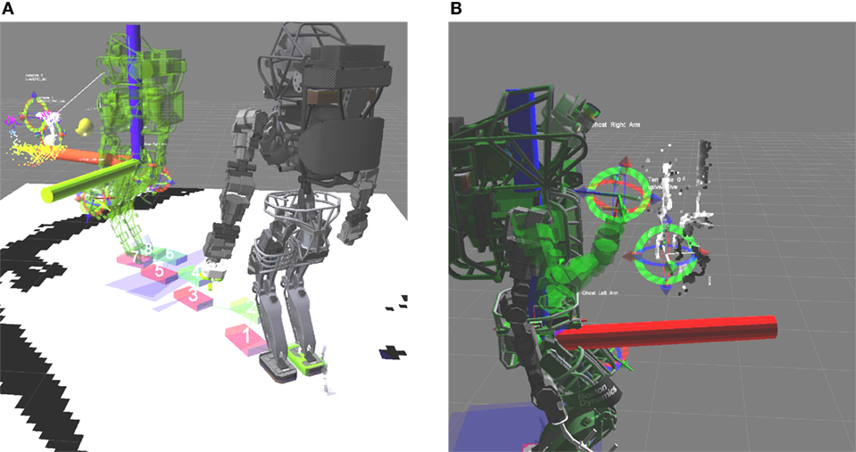
Figure 7. Two examples of using the ghost robot for previewing manipulation. (A) The ghost robot is used to preview the stand pose before performing manipulation. (B) Previewing arm motion during the valve task at the DRC Trials. The solid robot is the current true state, while the translucent green one is the ghost robot.
5.2. Planning System Details
Manipulation for disaster response often incorporates prolonged contact situations, for instance when opening a door or turning a valve. Especially in disaster response applications, cluttered environments present a challenge, as obstacles have to be avoided during motion planning.
The manipulation planning system is based on the MoveIt!7 (Chitta et al., 2012) motion planning framework available for ROS. This framework provides a powerful API for planning and different planning components.
The system enables planning to goal joint configurations and to goal end-effector poses and thus is directly compatible with the ghost robot approach described in the previous section. Two planning modes are available: the default mode is unconstrained planning, with joints free to move between the start and goal joint configurations. The other mode is a constrained motion mode. Here, motion is constrained to follow a Cartesian path between the start and goal end-effector pose. In this case, waypoints are generated based on linear interpolation between start and goal position and orientations for waypoints are generated using slerp (Shoemake, 1985) between start and goal end-effector quaternions. More complex constrained motions such as circular motion for turning a valve are generated by concatenating multiple short linearly interpolated Cartesian paths.
For obstacle avoidance, the volumetric octomap representation as described in Chapter 4 is used. As contact with the environment is required in many manipulation tasks, collision checking between end effectors and the environment can optionally be disabled by the supervisor(s). For instance, collision avoidance is needed to safely bring the robot hand into a position to pick up a drill. In order to grasp the drill, collisions between the palm and fingers of the hand and the drill handle must be allowed, however.
In challenging conditions, noise in sensor data that lead to geometric artifacts, preventing successful planning due to spurious collisions cannot be ruled out completely. To cope with such situations, collision checking against the octomap environment model can also be disabled for the complete robot geometry; in this case, the ghost robot changes color to warn the operator.
For motion planning, the number of joints (DOF) to use can be selected by the supervisor(s). For instance, on Atlas, planning can be performed using either 7 DOF with the arms only, or by including the torso joints and using up to 10 DOF. As the 10 DOF planning mode tends to result in higher control error or oscillation in some joint configurations, the operator can lock a selection of torso joints to restrict the planning space. The same approach can be used on other robotic systems transparently.
To allow for safety and robustness, the ability to select the desired trajectory execution speed with every planning request was introduced. Using standard MoveIt! functionality, trajectories were previously time parameterized according to the velocity limits supplied in the URDF robot model. This approach turned out to be not flexible enough for challenging manipulation in contact that might require moving appendages slow for safety.
5.3. Planning Interface
To implement the described manipulation back-end, the MoveIt! API was used and DRC-specific capabilities were implemented in a separate move_group capability plugin. This offers the advantage of retaining standard MoveIt! library planning features, while simultaneously allowing the development of extended capabilities specific for disaster response manipulation tasks.
As shown in Figure 8, the planning system is exposed via a ROS Action server interface and, thus, provides feedback about the planning and plan execution process. The Action interface is the sole entry point for requesting and executing motion plans and (in order of increasing autonomy) used for teleoperation, affordance-based manipulation planning and for motion plan requests generated by the behavior executive. For teleoperation, an onboard node translates compressed and compact motion requests by the operator into an Action request that then gets forwarded to the planning system.
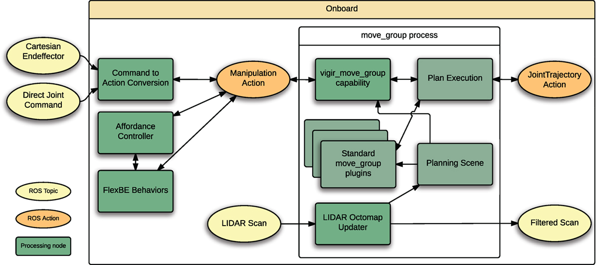
Figure 8. Overview of the planning back-end. Both the planning interface and the LIDAR octomap updater are loaded into the standard MoveIt! move_group process as plugins. Using this approach, existing functionality provided by MoveIt! is kept, but extended.
5.4. Supervised and Autonomous Control
The described planning system offers a powerful API that can be used to plan for complex manipulation tasks. In the preceding sections, both the teleoperation interface and the planning back-end are described.
To achieve both task-level supervised operation and autonomous control, two additional software components for manipulation use the described planning system as a back-end for performing manipulation: an object template framework and the FlexBE behavior engine.
Figure 9 shows an overview of how the different system components interact to achieve the full range of capability from teleoperation to full autonomy in interaction with one or more human supervisors.
5.4.1. Object Templates
Instead of directly controlling appendages, the object template-based approach for manipulation (Romay et al., 2014, 2015) uses models of objects to be manipulated, the so-called object templates. These are placed by the human operator in the virtual environment model where 3D sensor data of the environment are visualized and serve as references to achieve manipulation task at a higher level of abstraction.
Object Templates contain relevant information about the objects they represent, such as physical and abstract information. With this, the operator can provide the robot with potential standing poses, grasp poses, usable parts of the object, and manipulation skills or affordances (Gibson, 1977) to manipulate the object. With each template offering a set of affordances, motion can be specified by the operator on the affordance level. A door opening motion can, for instance, be commanded by using the “open” affordance defined for the door handle and the “push” affordance defined by the door hinge.
The information that object templates provide can also be abstracted by higher system layers, such as autonomous behaviors.
5.4.2. Automatic Behavior Control
For autonomous execution of complex manipulation and locomotion tasks, the Flexible Behavior Engine (FlexBE) has been developed during the DRC. A detailed overview is provided in Section 6. The object template system is also used within FlexBE to represent manipulatable objects. The behavior executable can, thus, take over responsibility for coordinating complex tasks from remote human supervisors where applicable.
5.5. Whole-Body Planning
While the developed motion planning system performs well for many manipulation tasks requiring only upper body motion, sampling-based planning falls short for planning whole-body motions that require the consideration of balance constraints. To also support this, the optimization-based planning approach available as part of the Drake framework (Fallon et al., 2015) has been integrated with the Team ViGIR planning system. Planning using Drake can transparently be used by specifying the plan request. Drake has also been integrated with the ghost robot on the OCS side and the operator can use Drake-based whole-body inverse kinematics to pre-plan tasks, such as reaching toward the ground for picking up objects.
5.6. Footstep Planning
A key challenge of the DRC was enabling the robot be able to tackle locomotion tasks, such as the traversal of sloped stairs, ramps, and rubble. While Team ViGIR depended on a manufacturer supplied footstep controller for stepping and stability, the specification of footstep placements remained a significant challenge; Team ViGIR extended an existing planner for 2D environments to handle this more complex 3D terrain.
The footstep planner has to satisfy two main requirements: the planner has to solve the navigation problem of finding the shortest safe path in a given environment. Second, it has to generate a feasible sequence of footstep placements, which can be executed by the robot with minimal risk of failure. Additionally, the DRC competition discouraged the use of slow footstep planning approaches due to mission time limits. Here, operator performance highly depends on the speed and performance of the used footstep planning system, so planning efficiency becomes important. It is desirable that the planning system provides all parameters of the walking controller for each step, so that the complex low-level walking controller interface is completely hidden from the operator to reduce the chance of operator error. This kind of footstep planning systems has not been applied to human-size real robots in complex terrain scenarios, such as the DRC before.
5.6.1. Overview
Our footstep planning approach satisfies the requirements mentioned above and requires the operator to only provide a goal pose to start planning. During the DRC competition, we have introduced the first search-based footstep planner capable of generating sequences of footstep placements in full 3D under planning time constraints and using an environment model based on online sensor data (Stumpf et al., 2014). The planner solves the navigation problem of finding shortest and collision-free paths in difficult terrain scenarios while simultaneously computing footstep placements appropriate for a given walking controller. A 3D terrain generator allows to generate terrain models for the footstep planning system online. It is able to efficiently compute the full 6 DoF foot pose for foot placements based on 3D scans of the environment. In addition, a novel collision check strategy based on ground contact estimation allows the planner to consider overhanging steps, significantly enhancing performance in rough terrain scenarios.
The described approach has been successfully applied to three different biped humanoid robots during the DRC Finals. As the only team at the DRC Trials, we demonstrated that our approach is able to generate suitable footstep plans over entire obstacles that had been executed without interruptions (see Figure 10).
5.6.2. Terrain Modeling
Planning in difficult terrain scenarios needs a suitable 3D terrain model that can efficiently be generated and utilized by the footstep planner. Therefore, a terrain model generator8 was implemented which analogously to the worldmodel server (see section 4.1) accumulates all incoming LIDAR scans given as point clouds. All data are stored in a discrete octree to reduce the amount of needed memory and enable efficient data fusion.
For each point in an incoming point cloud, a normal estimation9 with respect to the point neighborhood is immediately performed. Afterwards, the octree is updated with this new information. Each node within the octree, thus, provides the 3D position of the scan point and the estimated surface normal. Through the sparse laser scan updates of the spinning LIDAR, this operation can be performed in real-time on a single core of a CPU. In general, performing this operation with stereo vision or RGB-D systems is possible too, but needs further investigation as they generate more noisy data.
The described approach allows to run real-time terrain model generation on a robotic system as long as it is capable of providing point clouds given in an absolute world frame.
5.6.3. Footstep Planning Framework
The main objective is to provide an integrated footstep planning framework that may be deployed easily into an existing ROS setup. Providing a framework, the planner has to be expandable for new features but closed for modifications. Any user of the framework should only have to implement and extend robot-specific elements to use the planning system instead of developing a modified version of an existing planner or even starting from scratch each time. Already implemented and, thus, proven algorithms are kept untouched, reducing the likelihood of errors and saving implementation effort. Although the framework must generalize well, it has to be able to solve difficult terrain task problems and utilize the versatile locomotion capabilities of robot-specific walking controllers.
In order to meet this objective, parameter (vigir_generic_params)10 and plugin (vigir_pluginlib)11 management systems have been implemented.
5.6.3.1. Parameter System
In real-world applications, different terrain scenarios need to be tackled (e.g., flat surface, stairs or sloped terrain). The footstep planner can perform best if an appropriate set of parameters is defined for each kind of terrain scenario. This allows the operator to easily switch between different planning behaviors. Furthermore, it is desirable to be able to modify a parameter set if the situation requires it. In general, these requirements can be solved using the available ROS message infrastructure. Frameworks, such as the presented footstep planner, however, are supposed to be extended with new features. The structure of parameter sets may vary during runtime that is in conflict to ROS messages requiring a static structure. A simple solution would be separate configuration files and well as user interfaces for each plugin. Due to high maintenance effort this, however, is undesirable.
5.6.3.2. Plugin System
The vigir_pluginlib provides the capability to manage versatile plugins that can be also used outside of the footstep planning domain. The approach is based on pluginlib that already allows for dynamically loading plugins using the ROS build infrastructure. We have extended the package into a semantic plugin management system. The practical implementation consists of two parts: the plugin base class and the plugin manager.
5.6.3.3. Framework Overview
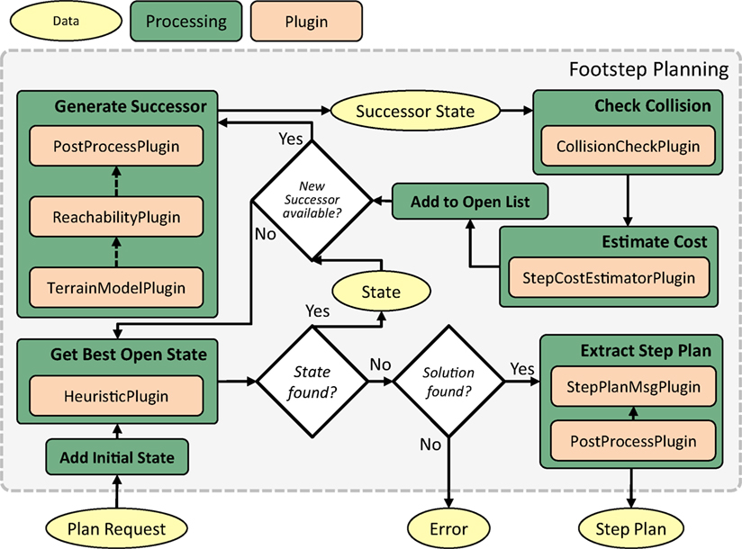
The plugin and parameter management systems form the infrastructure base of the footstep planning framework.12,13,14 The footstep planner pipeline has multiple injection points where a user might want to customize the behavior of the planner. For each of those, a semantic base class has been introduced as follows:
• CollisionCheckPlugin: basic collision check for a given state or transition,
• CollisionCheckGridMapPlugin: specialized CollisionCheckPlugin for occupancy grid maps,
• HeuristicPlugin: computes heuristic value from current state to goal state,
• PostProcessPlugin: allows performing additional computation after each step or step plan has been computed,
• ReachabilityPlugin: check if transition between two states is valid,
• StepCostEstimatorPlugin: estimates cost and risk for given transition,
• StepPlanMsgPlugin (unique): marshaling interface for robot specific data, and
• TerrainModelPlugin (unique): provides 3D model of environment.
The last two semantic base classes are defined to be unique; only a single instance might be running instance at a time. Figure 11 shows the use of plugins within the planner pipeline. For a quick deployment of the framework, concrete plugin implementations for common cases already exist for all semantic-based classes.
A major goal is maintaining footstep planner efficiency. Therefore, the computational overhead of the plugin system must be kept to a minimum. It obviously is inefficient to reload needed plugins in each single iteration of the planning process. For this reason, the planner loads all plugins only once and sets their parameters once before starting planning. Additionally, a mutex locks all critical callback functions of the planning system. The footstep planner is, thus, protected against any changes of the plugin as well as parameter manager during the planning process.
Advanced walking controllers usually need very specific data to allow for performing complex locomotion tasks. For instance, these data could be intermediate trajectory points of the foot or the convex hull of expected ground contact. The framework has been designed to be able to provide this capability. The plugin system allows to inject additional computation needed by the walking controller. Analogously to the parameter management system, all custom data can be carried as a byte stream within regular step plan messages. Marshaling algorithms already available for basic data types can be applied here as well. Marshaling for complex data types has to be implemented as a customized StepPlanMsgPlugin. The framework is, thus, able to pack all custom data into the generic step plan message and send it to the hardware adapter, where it gets unpacked and forwarded to the walking controller. The framework, thus, supports any kind of walking controller via the plugin system without required modifications to the framework code base.
5.6.4. Interactive Footstep Planning
During the DRC Trials, the inability to refine generated footstep plans was identified as a shortcoming. Even though the planner is able to generate feasible plans, the possibility that the resulting plan contains undesirable steps due to noisy sensor data remains. In this case, the operator previously had to request a new step plan in the hope to get a better result. For this reason, the footstep planning system was extended to provide multiple services to manage footstep plans. These services can be used by user interfaces to enable interactive footstep planning, allowing full human in the loop planning. This mode allows for plan stitching, plan revalidation, and editing single steps with assistance of the footstep planner. The operator is able to quickly adjust single steps, while the planner will automatically update the 3D position of the new foot pose if enabled and provides immediate feedback if the modified step sequence is still feasible for the walking controller.
6. Behavior Executive
Combination of multiple, complex software components on a high level is an often underestimated issue when composing robot systems. Existing solutions are often very application specific and require expert developers for implementing mission specifications. Thus, in order to provide a suitable task-level layer of control for full or assisted robot autonomy, the behavior engine FlexBE15 (Schillinger, 2015) has been developed. It is based on SMACH (Bohren and Cousins, 2010) and extends it by several helpful capabilities in order to facilitate both development and execution of high-level behaviors. Furthermore, FlexBE provides an extensive user interface, enabling even non-expert users to compose and execute mission specifications within short time frames. During runtime, execution can be monitored and controlled remotely and the robot autonomy level can be flexibly adjusted.
6.1. Component Interface
FlexBE (standing for “flexible behavior engine”) adapts the concept of hierarchical state machines similar to the implementation in SMACH. Each state corresponds to an action executed by the robot and transitions reflect the possible outcomes of these actions while data gathered during runtime can be passed between states. This approach enables to focus on the internal state of the robot (i.e., the current state of action execution). Knowledge about the external environment is only considered implicitly when designing a behavior, but is not needed to be exactly known during execution. Especially in disaster response, where the environment cannot be precisely modeled and events are typically the result of own actions, this concept helps to effectively define high-level behaviors.
Each action state is given by a class definition implementing a specific interface. Depending on the situation, a state returns one of its outcomes, leading to a transition in the respective containing state machine. Furthermore, states can declare input and output keys for sharing common data during runtime. As depicted by the concept overview in Figure 12, these state implementations form the atomic building blocks from which behaviors are composed. Each action state refers to a well-defined and encapsulated high-level capability of the robot, for example, closing fingers, planning footsteps, or executing a trajectory.
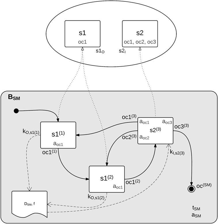
Figure 12. Conceptual overview of a behavior composition. Each behavior is defined by a hierarchical state machine that instantiates and connects (lower part) re-usable state implementations (upper part).
6.2. Behavior Development
In order to support the user in composing state instantiations to a complete behavior, FlexBE provides a comprehensive graphical user interface, including a state machine editor. Figure 13 shows a screenshot of this editor displaying a behavior as used for the DRC task of turning the valve. Yellow boxes denote states, white boxes are embedded state machines, and the boxes in pink refer to other complete stand-alone behaviors, which can be embedded as well. Transitions are given by arrows between the states, where their labels refer to the outcomes of the outgoing states, i.e., under which condition the respective transition is taken. Their color corresponds to the required level of autonomy, which can be selected by the user.
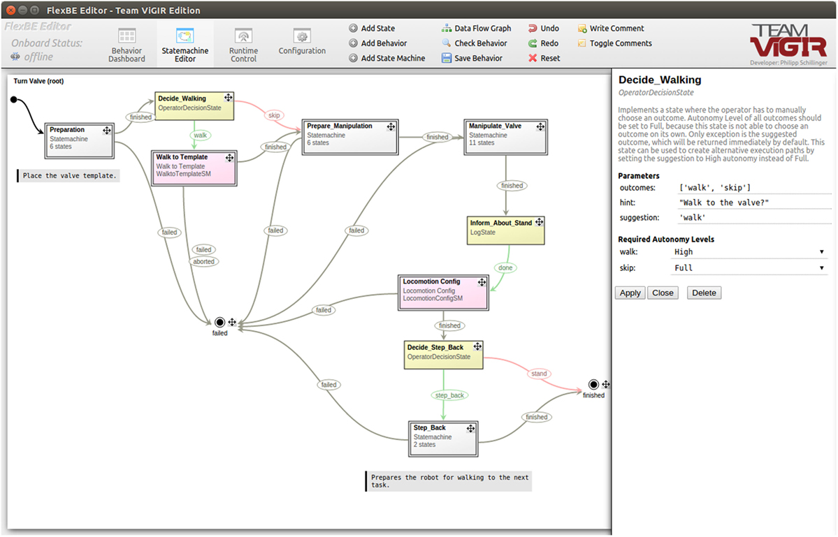
Figure 13. Behavior to solve the DRC task of turning the valve, visualized by FlexBE’s state machine editor. Even during execution, the structure can easily be re-arranged with just a few mouse-clicks and without manually writing code.
The editor also provides a set of useful tools for making sure that states are composed in the correct way. For example, a dataflow graph can be displayed in order to check how data will be accessed and potentially modified by the different robot capabilities during runtime. More importantly, each time a behavior is saved, or on demand, consistency of a behavior is validated. This includes checks such as that each outcome corresponds to a well-defined transition and no runtime data are potentially accessed before being written. FlexBE allows to make behavior modifications even during runtime and for updating behaviors while they are executed. With the static check functionality, the state machine editor ensures that such modifications do not lead to runtime failure.
Experience from designing task-level behaviors for the DRC showed that the usage of these concepts and the related tools not only helped facilitating the definition of complex behaviors since state machines could be modeled graphically instead of manually writing code, but also because a well-defined encapsulation of robot capabilities and the re-usability of all parts encouraged proper software engineering practices, such as modularity and a clear separation of control and data flow. Furthermore, the augmentation of states by detailed documentation was helpful when working with a multitude of different capabilities.
6.3. Behavior Execution
Execution of behaviors is embedded in the graphical user interface as well. During runtime, the currently active state is displayed in the center, with transitions pointing to the possible successor states. While a robot would always proceed to the next state whenever possible in full autonomy, the operator is able to limit the autonomy level of the robot in order to prevent wrong transitions in phases of limited situational awareness. If a transition requires more autonomy than allowed by the operator, this transition will be highlighted in the runtime control user interface and the operator is asked to either confirm or decline this decision. The operator can also force a completely different one at any time.
Although this concept of collaborative autonomy is helpful for the control flow of behaviors, the operator also needs to be able to provide specific data to the robot as required during runtime if the robot fails to retrieve it on its own. For this purpose, an input data server is running as part of the OCS. Whenever requested by the robot, the operator can assist and provide the required data manually, for example, place an object template. This is invoked by using an input state, which is implemented as a robot capability like any other perception state.
In order to account for constrained communication, robot–operator collaboration is carefully designed to be bandwidth efficient. A behavior mirror component runs on the OCS and mimics the onboard behavior, requiring only minimal runtime updates. It is, thus, possible to abstract from the fact that the behavior is not running locally and components, such as the user interface, can work on this mirror in order to retrieve the data they need for monitoring the runtime status.
7. Experiments
7.1. DRC Finals
The DRC Finals took place at Pomona, CA, USA on June 5th and 6th 2015. In the DRC Finals, three teams used the software described in this work, demonstrating the claimed flexibility and modularity.
Unlike in the previously held DRC Trials, tasks were not attempted separately. Instead teams had 60 min time to score as many of the 8 tasks as they could. Each team was allowed two runs in the competition, one on the first and one on the second competition day. The first objective was reaching the door, behind which the other tasks were situated. This could be done either by starting the robot in a Polaris Ranger vehicle and letting the robot drive up to the goal line close to the door, or by starting outside the vehicle and letting the robot walk the whole distance. Scoring awarded 0 points for walking, 1 point for driving, and 1 point for egress from the vehicle. Teams could opt out from performing egress. In this case, a reset had to be called and the robot manually extracted from the vehicle, resulting in a 10 min reset penalty and no point for egress. Traversing the door was the next task, with one point for full traversal through the door frame.
After traversing the door, communication constraints went into effect, meaning that the high bandwidth connection for perception data had pseudo-random dropouts of up to 30 s length, with 1 s windows of communication in-between. Fifteen minutes before run end, the drop outs stopped, allowing for full communication again.
7.1.1. Team Hector
Team Hector used a THOR-MANG robot. While the system showed promising capabilities during the qualification for the DRC Finals and prior to them during testing, slope of the ground at the Trials and hardware problems resulted in the robot falling in both Final runs.
The driving task was performed reliably, but on both days the robot fell while attempting to perform the door task.
7.1.2. Team Valor
Team VALOR used the ESCHER robot in the DRC Finals. The team decided to not attempt the driving task. ESCHER was one of two robots that successfully walked the complete distance from the start point up to the door. The attempt at opening the door was not successful due to encountered hardware issues.
7.1.3. Team ViGIR
Team ViGIR used the most recent, untethered version of the BDI Atlas robot. Originally, the team intended to skip the driving task. When it became clear that it would be allowed to not perform egress, but instead call for a reset, a decision was made to attempt the driving task. The performance for both competition days is briefly described the next two paragraphs.
7.1.3.1. Finals Day One
Starting in the Polaris Ranger vehicle, teleoperation was used to drive the robot down the vehicle course. A worldmodel of the course was obtained through LIDAR and cameras, and it was visualized in the OCS as described in Section 4. With this perception information, operators were able to use a driving controller system that generated the necessary joint motions to actuate the steering wheel and actuate the gas pedal. Details on the driving controller system will be described in Section 7.2. After completing the driving course, an intervention (with an associated 10-min penalty pause as specified in the DRC rules) was then used to manually extract the robot from the car.
After the penalty time, the door task was attempted. During the attempt to perform the door task, the supervisor team noticed that high-level behavior execution did not work as intended. This was later traced back to a faulty setup of the communications bridge system and increased saturation of the wireless links used in the competition. The supervisor team, thus, switched from using assisted autonomy via FlexBE behaviors to using object templates and teleoperation. Operators inserted the door template in the OCS where the sensor data of the door was displayed and commanded the robot to walk to the pre-defined stance pose for opening the door. After locomotion was performed, the operators attempted to open the door using the “open” affordance defined in the door object template. The robot hand slipped away from the door handle and, thus, the autonomous execution of the affordance failed. For this reason, the operators switched to Cartesian-space teleoperation. Using this approach, the door was successfully opened as seen in Figure 14A. After opening the door, the operators manually commanded the robot to walk toward a stance pose to open the valve. The valve task was solved using mainly the affordance-level control provided by the valve object template (see Figure 14B). Finally, before being able to actuate the switch in the surprise task, time ran out, ending the run. A video is available online.16
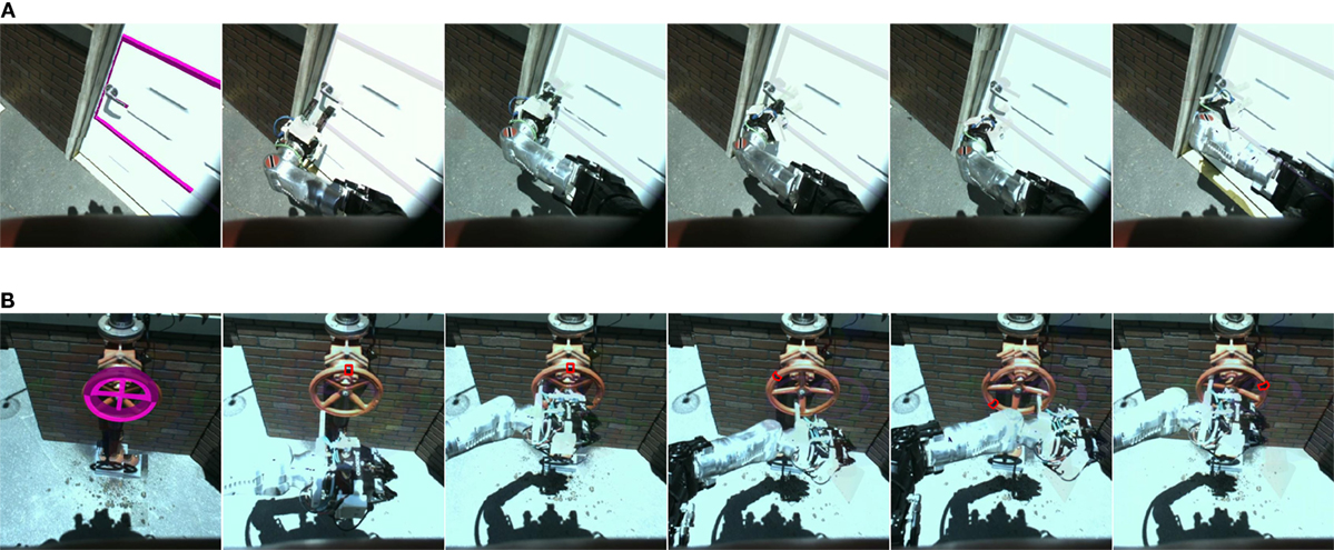
Figure 14. Team ViGIR Atlas robot view of performing tasks at the DRC Finals. (A) Door task. From left to right: Door Template aligned, Pre-grasp, Grasp, Turn Clockwise affordance, Push affordance (fails to open), door opened after Cartesian teleoperation. (B) Valve task. From left to right: Valve Template aligned, Pre-grasp, Grasp, Open affordance 45°, 135°, and 270°. Images courtesy of Alberto Romay.
7.1.3.2. Finals Day Two
The second-day mission again started by the supervisor team using teleoperation for driving the Polaris vehicle. Due to erratic network connectivity and possible operator error, a barrier was touched and a reset had to be called. In the second attempt, the driving task was performed successfully. The door opening task was performed using object template and automated behavior control. After the door was opened, the pump of the robot shut down for unknown reasons and the robot fell. After this forced reset, another attempt at traversing the door was made, resulting in another fall. A video is available online.17
7.1.4. Discussion
The perception system worked as designed during the competition, providing image and full LIDAR-based environment geometry data. It provided the necessary data also under communication constraints after traversing the door only allowed intermittent communication over the 300MBit high data rate connection from the robot.
All three teams using Team ViGIR’s software were able to leverage the contributions described in this work, which enabled them to perform supervised locomotion and manipulation with highly diverse bipedal robot systems. Due to encountered issues, the full potential, however, could not be demonstrated at the DRC Finals. The DRC competition operated on a tight schedule. This meant that delays in hardware availability presented significant challenges, as they would reduce the time available for testing software and training operators. This general constraint is a contributing factor to the issues encountered, such as the communications setup issue experienced, during the first day by Team ViGIR.
Open source whole-body controllers for the ATLAS and Thor-MANG robot were not available; instead manufacturer-provided libraries were used for low-level control of these robots. While capabilities offered by these libraries proved useful, their closed source nature provided little transparency and did not allow for tighter coupling between high-level and low-level control. The fact that ATLAS teams who developed their own controller based on prior research scored higher than those who used the BDI-supplied one supports this assertion.
While using a sliding level of autonomy up to full teleoperation worked well, offloading the task of object perception and pose estimation from supervisors is an aspect that has not been focused on so far. Instead, the described approach relied on providing supervisors with the necessary situational awareness to perform these tasks. Reliable automated solutions have the potential to improve performance and speed at which complex tasks can be performed.
7.2. Driving a Vehicle
Demonstrating the applicability of the framework to different robot systems and tasks, we focus here on the realization of the driving task for both the ATLAS and Thor-MANG robot as an example.
7.2.1. Controlling the Vehicle
To control the vehicle, both the steering wheel and gas pedal have to be actuated. Depending on the robot used, this can be challenging due to factors, such as size, strength, and sensing capabilities. To increase robustness, adapters that can be added to the Polaris Ranger XP900 vehicle were developed. As shown in Figure 15A, a knob attached to the steering wheel with a spring was used for steering control. While allowing for actuation of the steering wheel, the spring adds compliance to the setup and prevents high forces being exerted on either robot or vehicle. For the pedal shown in Figure 15B, an adapter was used that limits pedal travel as to limit the maximum speed of the vehicle. For the ATLAS robot, the adapter also had to mechanically transfer the steering command from the passenger side of the vehicle to the pedal, as the robot was too big to fit at the driver side. As a safety measure, a spring was added to the pedal adapter that always brings the adapter back into the idle position when not pressed down.
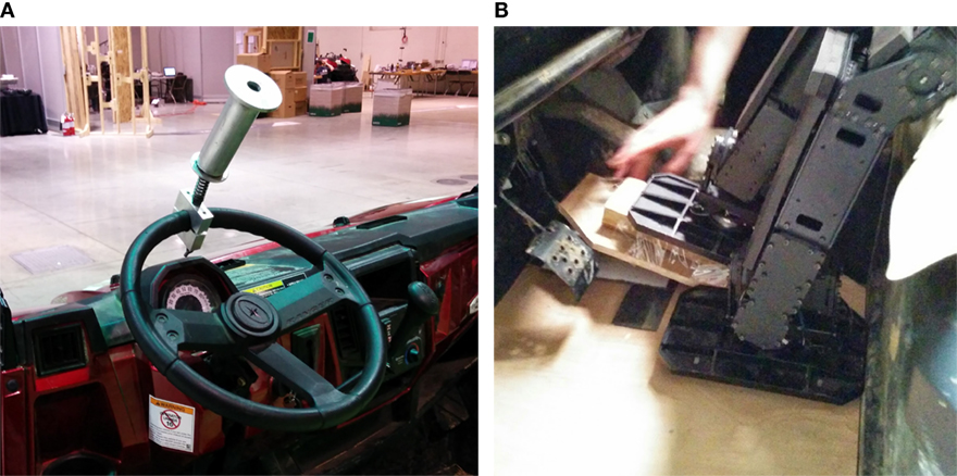
Figure 15. Hardware attachment for driving a car. (A) Compliant steering wheel adapter. (B) Pedal adapter for the Thor-MANG robot.
7.2.2. Perception
As generic and robust ego-motion estimation for humanoid robots placed in vehicles is highly challenging and prone to failure, a teleoperation-based approach was used. Steering angle and gas pedal angle are set by the operator. As a safety measure, the system automatically stops if no commands have been received within a threshold duration.
7.2.3. Results
In the DRC Finals, for both ATLAS and THOR-MANG, the capability to drive a car as required in the DRC Finals rules was demonstrated. A video is available online.18
7.3. Simulation
Due to the high cost of complex humanoid robot systems, it is highly desirable to be able to simulate them. This allows performing research and experiments when real systems are not available.
7.3.1. Simulation of Humanoids
The components described in this work are available as open source software and an example setup using the THOR-MANG robot in Gazebo simulation can be reproduced easily using available install instructions.19 A tutorial video showing the use of the example setup is available online.20
7.3.2. Example of Use with a Non-Biped Robot
Demonstrating the flexibility and modularity of the provided architecture, we show how manipulation capabilities can be added to a robot system that combines the proven mobility of a tracked base with a humanoid upper body.
The robot is capable of fully autonomous exploration of environments using the software components described in Kohlbrecher et al. (2014). In a demonstration video,21 it first explores parts of the environment fully autonomously, with the supervisor observing progress. When the supervisor notices that the closed door prevents the robot from continuing exploration, she uses the manipulation capabilities of the robot to open the door using teleoperation or affordance-level control using the contributions described in this work. Afterwards, the supervisor can command the robot to keep exploring the environment autonomously or continue operating in a lower autonomy mode. Instructions for install and use of the shown system are available online.22
8. Conclusion
This work discusses a comprehensive software framework for performing complex disaster response tasks using humanoid robots with human supervisors in the loop. System architecture design considerations are detailed and comprehensive contributions toward different aspects, such as communication, perception, manipulation and footstep planning, and behavior control, are detailed.
The described contributions are available as open source software23 for ROS. In contrast to other approaches, it has been successfully used on three different highly complex humanoid systems, demonstrating the flexibility and modularity of the system.
As discussed in the Section 7.1.4, while abstraction and decoupling from the low-level control system provided by robot systems can be considered a strength, achieving highest possible performance with a biped robot system requires full integration with and leveraging the capabilities of a whole-body control system. The realization of this is a subject of future work.
Author Contributions
SK: Perception and manipulation; AS: Footstep planner; AR: Object/affordance template approach; PS: FlexBE behavior engine; OS: Advisor, overall design; and DC: Advisor, overall design.
Conflict of Interest Statement
The authors declare that the research was conducted in the absence of any commercial or financial relationships that could be construed as a potential conflict of interest.
Footnotes
- ^https://github.com/RobotLocomotion/drake
- ^https://github.com/team-vigir/vigir_perception/tree/master/vigir_worldmodel_server
- ^https://github.com/team-vigir/vigir_manipulation_planning/tree/master/vigir_lidar_octomap_updater
- ^https://github.com/team-vigir/vigir_perception/tree/master/vigir_point_cloud_proc
- ^https://github.com/team-vigir/vigir_wide_angle_image_proc
- ^https://github.com/team-vigir/vigir_manipulation_planning
- ^http://moveit.ros.org/
- ^see https://github.com/team-vigir/vigir_terrain_classifier
- ^http://pointclouds.org/documentation/tutorials/normal_estimation.php
- ^https://github.com/team-vigir/vigir_generic_params
- ^https://github.com/team-vigir/vigir_pluginlib
- ^https://github.com/team-vigir/vigir_footstep_planning_msgs
- ^https://github.com/team-vigir/vigir_footstep_planning_basics
- ^https://github.com/team-vigir/vigir_footstep_planning_core
- ^http://flexbe.github.io
- ^https://youtu.be/VEsUICAa4rg
- ^https://youtu.be/Whw-tG0Wh9U
- ^https://www.youtube.com/watch?v=noxAK7YdJUE
- ^https://github.com/team-vigir/vigir_install/wiki/Install-thor-mang-vigir-gazebo
- ^https://www.youtube.com/watch?v=6fS89HGPEf4
- ^https://youtu.be/6ko27gKZGdA
- ^https://github.com/tu-darmstadt-ros-pkg/centaur_robot_tutorial
- ^https://github.com/team-vigir/vigir_install
References
Banerjee, N., Long, X., Du, R., Polido, F., Feng, S., Atkeson, C. G., et al. (2015). “Human-supervised control of the atlas humanoid robot for traversing doors,” in 15th IEEE-RAS International Conference on Humanoid Robots (Humanoids). Seoul.
Bohren, J., and Cousins, S. (2010). The SMACH high-level executive [ROS news]. IEEE Robot. Automat. Mag. 17, 18–20. doi:10.1109/MRA.2010.938836
Burget, F., and Bennewitz, M. (2015). “Stance selection for humanoid grasping tasks by inverse reachability maps,” in Robotics and Automation (ICRA), 2015 IEEE International Conference on, Seattle. 5669–5674.
Chitta, S., Sucan, I., and Cousins, S. (2012). MoveIt! IEEE Robot. Automat. Mag. 19, 18–19. doi:10.1109/MRA.2011.2181749
DRC-Teams. (2015). What Happened at the DARPA Robotics Challenge? Available at: http://www.cs.cmu.edu/~cga/drc/events/
Du, C., Lee, K.-H., and Newman, W. (2014). “Manipulation planning for the atlas humanoid robot,” in Robotics and Biomimetics (ROBIO), 2014 IEEE International Conference on, 1118–1123.
Fallon, M., Kuindersma, S., Karumanchi, S., Antone, M., Schneider, T., Dai, H., et al. (2015). An architecture for online affordance-based perception and whole-body planning. J. Field Robot. 32, 229–254. doi:10.1002/rob.21546
Gibson, J. J. (1977). “The theory of affordances,” in Perceiving, Acting, and Knowing, eds R. Shaw and J. Bransford (Madison, WI), 67–82.
Holz, D., and Behnke, S. (2013). “Fast range image segmentation and smoothing using approximate surface reconstruction and region growing,” in Intelligent Autonomous Systems 12, Volume 194 of Advances in Intelligent Systems and Computing, eds S. Lee, H. Cho, K.-J. Yoon, and J. Lee (Berlin, Heidelberg: Springer), 61–73.
Hornung, A., Wurm, K. M., Bennewitz, M., Stachniss, C., and Burgard, W. (2013). Octomap: an efficient probabilistic 3D mapping framework based on octrees. Auton. Robots 34, 189–206. doi:10.1007/s10514-012-9321-0
Huang, A. S., Olson, E., and Moore, D. C. (2010). “LCM: Lightweight communications and marshalling,” in Intelligent Robots and Systems (IROS), 2010 IEEE/RSJ International Conference on. Taipei: IEEE.
Johnson, M., Bradshaw, J. M., Feltovich, P. J., Jonker, C. M., Van Riemsdijk, M. B., and Sierhuis, M. (2014). Coactive design: designing support for interdependence in joint activity. J. Hum. Robot Interact. 3, 2014. doi:10.5898/JHRI.3.1.Johnson
Johnson, M., Shrewsbury, B., Bertrand, S., Wu, T., Duran, D., Floyd, M., et al. (2015). Team IHMC’s lessons learned from the DARPA robotics challenge trials. J. Field Robot. 32, 192–208. doi:10.1002/rob.21571
Kohlbrecher, S., Meyer, J., Graber, T., Petersen, K., Klingauf, U., and von Stryk, O. (2014). “Hector open source modules for autonomous mapping and navigation with rescue robots,” in RoboCup 2013: Robot World Cup XVII, Volume 8371 of Lecture Notes in Computer Science, eds S. Behnke, M. Veloso, A. Visser, and R. Xiong (Berlin, Heidelberg: Springer), 624–631.
Kohlbrecher, S., Romay, A., Stumpf, A., Gupta, A., von Stryk, O., Bacim, F., et al. (2015). Human-robot teaming for rescue missions: team ViGIR’s approach to the 2013 DARPA robotics challenge trials. J. Field Robot. 32, 352–377. doi:10.1002/rob.21558
Leeper, A., Hsiao, K., Ciocarlie, M., Sucan, I., and Salisbury, K. (2013). “Methods for collision-free arm teleoperation in clutter using constraints from 3D sensor data,” in IEEE Intl. Conf. on Humanoid Robots (Atlanta, GA).
Quigley, M., Conley, K., Gerkey, B. P., Faust, J., Foote, T., Leibs, J., et al. (2009). “ROS: an open-source robot operating system,” in ICRA Workshop on Open Source Software. Kobe.
Romay, A., Kohlbrecher, S., Conner, D. C., Stumpf, A., and von Stryk, O. (2014). “Template-based manipulation in unstructured environments for supervised semi-autonomous humanoid robots,” in Humanoid Robots (Humanoids), 2014 14th IEEE-RAS International Conference on (Madrid: IEEE), 979–986.
Romay, A., Kohlbrecher, S., Conner, D. C., and von Stryk, O. (2015). “Achieving versatile manipulation tasks with unknown objects by supervised humanoid robots based on object templates,” in IEEE-RAS Intl. Conf. on Humanoid Robots. Seoul.
Rusu, R. B., and Cousins, S. (2011). “3D is here: point cloud library (PCL),” in Robotics and Automation (ICRA), 2011 IEEE International Conference on (Shanghai: IEEE), 1–4.
Scaramuzza, D., and Siegwart, R. (2007). “A practical toolbox for calibrating omnidirectional cameras,” in Vision Systems Applications. Vienna: I-Tech Education and Publishing.
Schillinger, P. (2015). An Approach for Runtime-Modifiable Behavior Control of Humanoid Rescue Robots. Master’s thesis. Technische Universität Darmstadt, Darmstadt.
Schillinger, P., Kohlbrecher, S., and von Stryk, O. (2016). “Human-robot collaborative high-level control with application to rescue robotics,” in Proc. IEEE Int. Conf. on Robotics and Automation (ICRA).
Shoemake, K. (1985). Animating rotation with quaternion curves. ACM SIGGRAPH Comput. Graph. 19, 245–254. doi:10.1145/325165.325242
Stumpf, A., Kohlbrecher, S., Conner, D. C., and von Stryk, O. (2014). “Supervised footstep planning for humanoid robots in rough terrain tasks using a black box walking controller,” in Humanoid Robots (Humanoids), 2014 14th IEEE-RAS International Conference on (Madrid: IEEE), 287–294.
Tang, P., Huber, D., and Akinci, B. (2007). “A comparative analysis of depth-discontinuity and mixed-pixel detection algorithms,” in D Digital Imaging and Modeling, 2007. 3DIM’07. Sixth International Conference on (Montreal: IEEE), 29–38.
Tuley, J., Vandapel, N., and Hebert, M. (2005). “Analysis and removal of artifacts in 3-D ladder data,” in Robotics and Automation, 2005. ICRA 2005. Proceedings of the 2005 IEEE International Conference on (Barcelona: IEEE), 2203–2210.
Vahrenkamp, N., Asfour, T., and Dillmann, R. (2013). “Robot placement based on reachability inversion,” in Robotics and Automation (ICRA), 2013 IEEE International Conference on (Karlsruhe: IEEE), 1970–1975.
Keywords: urban search and rescue, humanoid robots, mobile manipulation, human–robot interaction, motion planning
Citation: Kohlbrecher S, Stumpf A, Romay A, Schillinger P, von Stryk O and Conner DC (2016) A Comprehensive Software Framework for Complex Locomotion and Manipulation Tasks Applicable to Different Types of Humanoid Robots. Front. Robot. AI 3:31. doi: 10.3389/frobt.2016.00031
Received: 07 December 2015; Accepted: 13 May 2016;
Published: 07 June 2016
Edited by:
Fumio Kanehiro, National Institute of Advanced Industrial Science and Technology, JapanCopyright: © 2016 Kohlbrecher, Stumpf, Romay, Schillinger, von Stryk and Conner. This is an open-access article distributed under the terms of the Creative Commons Attribution License (CC BY). The use, distribution or reproduction in other forums is permitted, provided the original author(s) or licensor are credited and that the original publication in this journal is cited, in accordance with accepted academic practice. No use, distribution or reproduction is permitted which does not comply with these terms.
*Correspondence: Stefan Kohlbrecher, a29obGJyZWNoZXJAc2ltLnR1LWRhcm1zdGFkdC5kZQ==
 Stefan Kohlbrecher
 Alexander Stumpf
 Alberto Romay
 Philipp Schillinger
 Oskar von Stryk
 David C. Conner