 Wenqiang Gao
 Teng Zhang1
 Qinglin Niu
95% of researchers rate our articles as excellent or good
Learn more about the work of our research integrity team to safeguard the quality of each article we publish.
Find out more
BRIEF RESEARCH REPORT article
Front. Phys. , 29 January 2025
Sec. Optics and Photonics
Volume 13 - 2025 | https://doi.org/10.3389/fphy.2025.1546228
This article is part of the Research Topic Advanced Methods in Exploring Light-Matter Interactions and Their Applications View all 7 articles
Infrared imaging is essential for detecting multiple unmanned aerial vehicle (UAV) targets detection to capture flight altitude and behavior. This study focused on a typical stealth UAV formation with a flying-wing configuration. Considering the attenuation effects of clouds and rain on the infrared spectrum, a ground-based infrared imaging algorithm was developed. Infrared radiation imaging was conducted using the apparent ray tracing method and mesh clipping technology. The infrared radiation intensity distribution of the UAV formation target within the 8.0–12.0 μm band was calculated, and infrared thermal images incorporating the occlusion effect were obtained. The results showed that the radiance of the multi-UAV formation was approximately 8.0 × 10⁻⁵ W/Sr, which was 103–104 orders of magnitude lower than that under standard atmospheric conditions under cloudy weather conditions. The infrared radiance was approximately 1.7 × 10⁻⁵ W/Sr, which was 104–105 lower than that under standard atmospheric conditions under rainy weather conditions.
Unmanned aerial vehicles are widely used in military, civil and commercial fields owing to rapid technological developments [1–3]. However, detection methods such as radar and acoustics have several limitations owing to their small size, low flight height, and strong maneuverability [4, 5]. An infrared system uses an infrared sensor to capture the thermal radiation generated by the temperature difference between the UAV and surrounding environment. Infrared detection is highly sensitive and accurate in complex environments, particularly under low-visibility conditions [6].
However, weather conditions such as clouds and rainfall significantly affect infrared detection performance [7, 8]. Clouds and raindrops absorb and scatter infrared radiation, thereby attenuating the signal strength of detection systems, particularly in the mid-wave and long-wave infrared bands. The thickness and type of clouds, along with the intensity of precipitation, directly influence the detection capability of infrared sensors. Infrared signals from UAV can be significantly attenuated under thick clouds or heavy rainfall, thereby complicating detection.
The impact of participatory media on infrared imaging algorithms such as the Monte Carlo method and ray tracing cannot be neglected, particularly for infrared radiation transmission through the atmosphere or clouds. The Monte Carlo method simulates the propagation path of light by random sampling and computes its interaction with the medium, which is suitable for modeling heterogeneous media in complex environments. However, the method is computationally intensive, exhibits low processing speeds, and is often limited by the number of samples and available computing resources [9]. The ray-tracing method enhances computational efficiency while maintaining high accuracy. However, the modeling of complex scattering and absorption processes is less precise than that of the Monte Carlo method [10, 11]. In recent years, scholars have increasingly explored infrared imaging algorithms based on deep neural networks (DNNs) [12], driven by advancements in the combination of deep learning and physical modeling. For example, a convolutional neural network (CNN) based approach was proposed to enhance infrared image clarity and detail in low-light environments [13]. Additionally, to improve both real-time performance and accuracy, time series models, such as long short-term memory (LSTM) networks, and generative adversarial networks (GANs) have been applied to infrared imaging [14, 15]. However, sufficient samples must be generated for model training.
This study focuses on UAV formation targets. The flow field, radiative transfer and infrared imaging computations of multiple targets are required. The complex structure of the targets requires several grids, making batch computation inconvenient. To reduce the computational cost, the apparent ray-tracing method was combined with the mesh clipping technique. Infrared radiation imaging calculations during the target cruise flight were performed under cloudy and rainy atmospheric conditions, and the effect of weather conditions on infrared imaging was systematically examined.
When the target is in flight, a flow field is generated around the body owing to the compression and friction of the surrounding air. This flow field can be described using the compressible Navier-Stokes equations, based on the continuum assumption. The governing conservation equations for mass, momentum, and energy are expressed in Equations 1–3:
where
The Reynolds-averaged method [16] was employed to solve the above equations, while balancing the computational accuracy and cost. The shear stress transport (SST) turbulence model [17] is used to close the system, accounting for the characteristics of the adverse pressure gradient boundary layer. The viscous fluxes were calculated using a second-order central difference scheme, and steady-state solutions were obtained using the time-marching method.
The expression for calculating the wall heat flux of the target during flight is Equation 4:
where the first term on the right represents the convective heat flux, while the second term corresponds to the component diffusion heat flux. Here,
Under the thin-wall approximation, the heat flux balance in the direction perpendicular to the wall can be expressed as Equation 5:
where
The radiation emitted by the aircraft body is detected by the sensor after atmospheric attenuation along its path. The intrinsic radiation is governed by the wall surface temperature, skin emissivity, wavelength range, and effective radiating area. According to Planck’s law of blackbody radiation [19], the radiation emittance of the UAV within the specified band
where
The radiation intensity from the visible area of the UAV in the detection direction can be expressed as Equation 7:
where
For ground-based infrared detection systems, the atmospheric environment absorbs and scatters infrared radiation within different wavelength bands. Radiation emitted from the target surface is inevitably attenuated by the atmosphere before reaching the detector. Atmospheric transmittance along the detection path under cloud and rain conditions is calculated using the MODTRAN software [20].
The relationship between the atmospheric spectral transmittance
where
where
Field-of-view effects occur during detection and imaging by ground-based detection systems. The target surface element grid may have multiple layers stacked on top of each other, which affect the visible area calculation. Meanwhile, the overlap between the target surface element grid and a part of the detector image element grid affects the effective radiation area calculation. However, both affect the calculation accuracy and cause the imaging mottling effect, as shown in Figure 1.
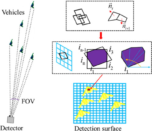
Figure 1. Schematic of detection and mesh clipping.
The mesh clipping technique was employed to calculate the area of overlap between the target mesh and detector pixel grid on the projection plane, as described below.
1) Vertex coordinates of overlapping polygons: The vertex coordinates of the two meshes were directly obtained. For the intersection points, a linear equation was derived for the detector grid boundary using one edge of the target grid as the reference. The intersection points were determined by simultaneously solving Equations. 2) Overlap area calculation: The overlapping polygon was divided into triangles. The vertices were reordered in the clockwise direction based on their cosine values, forming a closed geometric unit. 3) Calculation of effective infrared radiation intensity: The radiation intensity received by the detector pixel was calculated using the effective radiation area obtained from mesh clipping and the spatial relationship between the surface unit and detector pixel, expressed in Equation 10:
where
The UAV formation flew at a cruising speed of 220 m/s at an altitude of 0.7 km. Atmospheric parameters at different altitudes were obtained from the United States Standard Ambient Atmospheric Database [22]. First, the target geometric model was structurally meshed using ANSYS ICEM and the wall temperature was calculated using CFD. The intrinsic radiation of the targets was obtained using Planck’s blackbody radiation law. The radiative transfer problem was solved by reducing the radiative transfer in a three-dimensional inhomogeneous medium to that in a one-dimensional multilayer medium [23]. The detector pupil size was 0.2 m × 0.2 m, with 256 × 256 pixels and a detection distance of 0.7 km. MODTRAN was used to calculate the atmospheric transmittance. The target infrared thermal images were obtained using mesh clipping. The calculation procedure is presented in Figure 2.
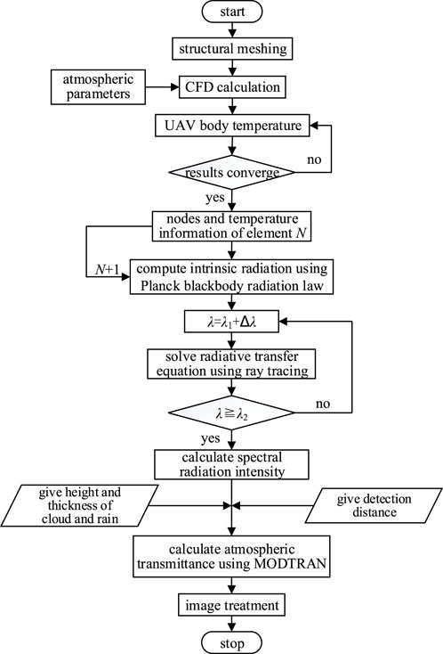
Figure 2. Computational procedure for UAV IR radiation and IR imaging.
To analyze the effect of cloud meteorological conditions on the infrared imaging of the UAV formation, MODTRAN was used to calculate atmospheric transmittance. The cloud meteorological conditions had layer heights of 0.66 km and 3.0 km at the bottom and top of the cloud, respectively. The atmospheric transmittances in the 2.0–14.0 μm band for cumulus clouds and standard atmospheric condition were obtained, as shown in Figure 3A. The transmittance is band-dependent, exhibiting a clear transmittance window. The transmittances in the 2.0–5.6 μm and 8.0–14.0 μm bands are relatively large between the cumulus clouds and standard atmospheric conditions. Within the same band, the atmospheric transmittance of cumulus clouds was 102–103 orders of magnitude lower than that under standard atmospheric conditions.
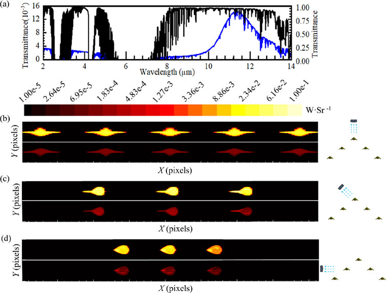
Figure 3. Transmittance profiles and infrared thermographies: (A) atmospheric transmittance profiles in the 2.0–14.0 μm band and infrared thermographies of the multi-UAV formation under (B) front view, (C) oblique view and (D) side view for cumulus cloud and standard atmospheric conditions.
The peak and average temperatures of the UAV wall during cruise flight were approximately 320 K and 280 K, respectively. According to Planck’s law of blackbody radiation, the peak emission shifts to shorter wavelengths with increasing temperature. Infrared thermal images within the 8.0–12.0 μm band of the UAV formation were obtained under standard atmospheric and cumulus conditions using the aforementioned computational method. Thermal images of the UAV formation for three typical detection directions are shown in Figures 3B–D. The top and bottom halves of each thermal image depict the UAV formation under standard atmospheric and cumulus cloud conditions, respectively. Cloudy weather significantly affects the radiance of infrared thermal images. The radiance of the multi-UAV formation was approximately 8.0 × 10⁻⁵ W/Sr under cumulus clouds, which was 103–104 orders of magnitude lower than that under standard atmospheric conditions under different detection views. The maximum visible area of a single UAV was approximately 0.1 m2 while the minimum was 0.07 m2 affected under occlusion. The peak radiance was 0.05 W/Sr and 3.0 × 10⁻⁴ W/Sr for standard atmospheric and cloudy conditions, respectively. However, the peak radiance remained almost unchanged at different observation angles.
This section describes the use of MODTRAN to calculate the atmospheric transmittance under heavy rainfall. These conditions correspond to rainfall of 250 mm/h and 0.2 mm/h at ground level and 3.0 km, respectively. The atmospheric transmittance within the 2.0–14.0 μm band under heavy rain conditions is shown in Figure 4A. Similar to the cumulus cloud conditions, transmittance windows are observed under heavy rain within the 2.0–5.6 μm and 10.0–14.0 μm bands. The atmospheric transmittance under heavy rain is lower than the standard atmospheric transmittance by 103 orders of magnitude.
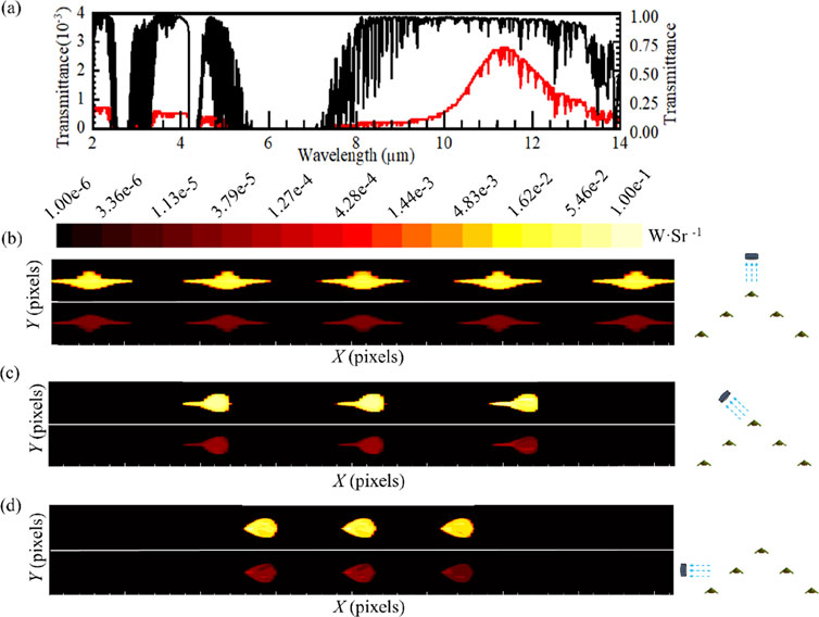
Figure 4. Transmittance profiles and infrared thermographies: (A) atmospheric transmittance profiles in the 2.0–14.0 μm band and infrared thermographies of the multi-UAV formation under (B) front view, (C) oblique view and (D) side view for heavy rain and standard atmospheric conditions.
Infrared thermal images of the UAV formation within the 8.0–12.0 μm band under standard atmospheric and heavy rain conditions are shown in Figures 4B–D. The top and bottom halves of each thermal image show the UAV formation under standard atmospheric and heavy rain conditions, respectively. Heavy rain primarily affects the radiant intensity values in infrared thermal images. The average infrared radiance is approximately 1.7 × 10⁻⁵ W/Sr under rainy weather conditions. Under heavy rainfall, the radiance is approximately 104–105 orders of magnitude lower than that under standard atmospheric conditions. The maximum effective radiant area of a single UAV was approximately 0.1 m2, while the minimum was 0.06 m2 under occlusion. The peak radiance values were 0.05 W/Sr and 6.0 × 10⁻⁵ W/Sr for standard atmospheric and for cloudy conditions, respectively. The peak radiance remained unchanged at different observation angles.
This study investigated infrared radiation imaging of a multi-UAV formation with a flying-wing configuration under cloudy and rainy conditions. The infrared radiance emitted by the multi-UAV formation was computed using flow calculation methods and Planck blackbody radiation law. Infrared imaging was performed using mesh clipping technique. The main conclusions are as follows.
(1) The impact of cloud-atmosphere conditions on infrared thermal images was primarily reflected in the radiance. The radiance of the UAV formation within the 8.0–12.0 μm band was approximately 8.0 × 10⁻⁵ W/Sr under cumulus conditions, which was 103–104 orders of magnitude lower than that under standard atmospheric conditions.
(2) The variation in radiance primarily indicated the influence of rainy conditions on infrared thermal images. Within the 8.0–12.0 μm band and under heavy rain conditions, the radiance of the infrared radiation of the UAV formation was approximately 1.7 × 10⁻⁵ W/Sr, which was 104–105 orders of magnitude lower by than that under standard atmospheric conditions.
The original contributions presented in the study are included in the article/supplementary material, further inquiries can be directed to the corresponding author.
WG: Data curation, Writing–original draft. TZ: Data curation, Writing–review and editing. ET: Supervision, Writing–review and editing. PZ: Writing–review and editing. QN: Methodology, Writing–review and editing.
The author(s) declare that financial support was received for the research, authorship, and/or publication of this article. This research was funded by the National Nature Science Foundation of China (No. U22B2045), the Fundamental Research Program of Shanxi Province (No. 202403021211078).
The authors declare that the research was conducted in the absence of any commercial or financial relationships that could be construed as a potential conflict of interest.
The authors declare that no Generative AI was used in the creation of this manuscript.
All claims expressed in this article are solely those of the authors and do not necessarily represent those of their affiliated organizations, or those of the publisher, the editors and the reviewers. Any product that may be evaluated in this article, or claim that may be made by its manufacturer, is not guaranteed or endorsed by the publisher.
1. Mohsan SAH, Othman NQH, Li Y, Alsharif MH, Khan MA. Unmanned aerial vehicles (UAVs): practical aspects, applications, open challenges, security issues, and future trends. Intell Serv Robotics (2023) 16(1):109–37. doi:10.1007/s11370-022-00452-4
2. Criollo L, Mena-Arciniega C, Xing S. Classification, military applications, and opportunities of unmanned aerial vehicles. Aviation (2024) 28(2):115–27. doi:10.3846/aviation.2024.21672
3. Shakhatreh H, Sawalmeh AH, Al-Fuqaha A, Dou ZC, Almaita E, Khalil I, et al. Unmanned aerial vehicles (UAVs): a survey on civil applications and key research challenges. Ieee Access (2019) 7:48572–634. doi:10.1109/access.2019.2909530
4. Semenyuk V, Kurmashev I, Lupidi A, Alyoshin D, Kurmasheva L, Cantelli-Forti A. Advance and refinement: the evolution of UAV detection and classification technologies (2024). p. 05985. arXiv preprint arXiv, 2409.
5. Brown AD. Radar challenges, current solutions, and future advancements for the counter unmanned aerial systems mission. IEEE Aerospace Electron Syst Mag (2023) 38(9):34–50. doi:10.1109/maes.2023.3289928
6. Andraši P, Radišić T, Muštra M, Ivošević J. Night-time detection of UAVs using thermal infrared camera. Transportation Res Proced (2017) 28:183–90. doi:10.1016/j.trpro.2017.12.184
7. Zhang YN, Zhang HC, Ma R, Song NQ, Wei YQ. Evaluation of infrared thermal in different cloud imaging system detection distance and rain conditions. J Appl Opt (2016) 37(2):288–96. doi:10.5768/JAO201637.0206001
8. Raheem AFA, Raheem AA, Fuliful FK. Investigation of thermal imaging under bad weather conditions. AIP Conf Proc (2022) 2386(1):070004. doi:10.1063/5.0067096
9. Howell JR, Daun KJ. The past and future of the Monte Carlo method in thermal radiation transfer. J Heat Transfer (2021) 143(10):100801. doi:10.1115/1.4050719
10. Chang PC, Walker JG, Hopcraft KI. Ray tracing in absorbing media. J quantitative Spectrosc radiative transfer (2005) 96(3-4):327–41. doi:10.1016/j.jqsrt.2005.01.001
11. Tan HP, Lallemand M. Transient radiative-conductive heat transfer in flat glasses submitted to temperature, flux and mixed boundary conditions. Int J Heat Mass Transfer (1989) 32(5):795–810. doi:10.1016/0017-9310(89)90229-9
12. He Y, Deng B, Wang H, Cheng L, Zhou K, Cai S, et al. Infrared machine vision and infrared thermography with deep learning: a review. Infrared Phys and Technol (2021) 116:103754. doi:10.1016/j.infrared.2021.103754
13. Kuang X, Sui X, Liu Y, Chen Q, Gu G. Single infrared image enhancement using a deep convolutional neural network. Neurocomputing (2019) 332:119–28. doi:10.1016/j.neucom.2018.11.081
14. Mei S, Li X, Liu X, Cai H, Du Q. Hyperspectral image classification using attention-based bidirectional long short-term memory network. IEEE Trans Geosci Remote Sensing (2021) 60:1–12. doi:10.1109/tgrs.2021.3102034
15. Lyu X, Jia T, Liu Y, Shan P, Li L, Zhao Y. An improved infrared simulation method based on generative adversarial networks. Infrared Phys and Technology (2024) 140:105424. doi:10.1016/j.infrared.2024.105424
16. Yakhot V, Orszag SA. Renormalization group analysis of turbulence. I. Basic theory. J Scientific Comput (1986) 1(1):3–51. doi:10.1007/bf01061452
17. Menter FR. Two-equation eddy-viscosity turbulence models for engineering applications. AIAA J (1994) 32(8):1598–605. doi:10.2514/3.12149
18. Boltzmann L (1884). Über die Beziehung zwischen dem zweiten Hauptsatz der Mechanik und der Wärmelehre. Sitzungsberichte der Akademie der Wissenschaften in Wien, 93, 408–48.
19. Planck M. On the law of distribution of energy in the normal spectrum. Annalen der Physik, 4th Ser (1901) 309(3):553–63.
21. Mayerhöfer TG, Pahlow S, Popp J. The bouguer-beer-lambert law: shining light on the obscure. ChemPhysChem (2020) 21(18):2029–46. doi:10.1002/cphc.202000464
22. Atmosphere US. US standard atmosphere. Washington, DC: National Oceanic and Atmospheric Administration (1976).
Keywords: ground-based infrared thermography, UAV formation, cloud and rain weather, atmospheric transmittance, mesh clipping
Citation: Gao W, Zhang T, Tang E, Zhang P and Niu Q (2025) Numerical investigation of infrared imaging of multi-UAV formation under cloud and rain weather conditions. Front. Phys. 13:1546228. doi: 10.3389/fphy.2025.1546228
Received: 16 December 2024; Accepted: 06 January 2025;
Published: 29 January 2025.
Edited by:
Zhaohong Liu, Hebei University of Technology, ChinaReviewed by:
Linyang Wei, Northeastern University, ChinaCopyright © 2025 Gao, Zhang, Tang, Zhang and Niu. This is an open-access article distributed under the terms of the Creative Commons Attribution License (CC BY). The use, distribution or reproduction in other forums is permitted, provided the original author(s) and the copyright owner(s) are credited and that the original publication in this journal is cited, in accordance with accepted academic practice. No use, distribution or reproduction is permitted which does not comply with these terms.
*Correspondence: Enling Tang, dGFuZ2VubGluZ0AxMjYuY29t
Disclaimer: All claims expressed in this article are solely those of the authors and do not necessarily represent those of their affiliated organizations, or those of the publisher, the editors and the reviewers. Any product that may be evaluated in this article or claim that may be made by its manufacturer is not guaranteed or endorsed by the publisher.
Research integrity at Frontiers
Learn more about the work of our research integrity team to safeguard the quality of each article we publish.