- College of Mechatronic Engineering, North University of China, Taiyuan, China
Measuring the bore of artillery barrels is often a challenging task due to limited automation, inaccuracies in measurement, and the need to process large volumes of test data. To tackle these issues, research has focused on utilizing high-precision laser technology for scanning and detecting barrel bores. This process involves creating a three-dimensional (3D) reconstruction of the bore morphology based on the collected test data. This work addresses the problem of eccentricity error during detection by developing a rotational model of the robot within the bore. The model aids in analyzing errors and introduces a position calibration method that utilizes a double Position Sensitive Detector (PSD). The bore of the barrel has been reconstructed using the Delaunay triangular section interpolation algorithm, resulting in a 3D contour structure of the artillery barrel bore. Experimental results demonstrate that the profile curve of the artillery barrel bore exhibits significant fluctuations before calibration, but becomes much more stable afterward. The maximum degree of calibration achieved was up to 40%. The 3D reconstructed model displays robust structural integrity and offers compelling visual corroboration for the test data. Furthermore, the recti-linearity of the corrected 3D model of the artillery barrel has been significantly improved in this work.
1 Introduction
Artillery plays a pivotal role in modern warfare. The barrel is a core component of artillery that is directly in contact with the shell, and the quality of its bore surface significantly affects the initial velocity of the shell, the operational lifespan of the artillery, and the precision of the strike [1, 2]. Throughout its lifespan, the rifling inside the barrel experiences considerable wear and tear due to exposure to high temperatures and pressures, which ultimately impacts the performance of the firearm [3]. Therefore, it is essential to realize automatic, rapid, and accurate measurements of the inner chamber of the artillery barrel. This will aid in determining the technical status of the barrel, assessing the condition of its inner chamber, and developing effective maintenance and service plans.
In both domestic and international contexts, the methods used to detect bore measurements in artillery barrels can be broadly categorized into two main types: contact detection and non-contact detection [4, 5]. Contact measurement methods primarily utilize mechanical instruments [6], including mechanical star calibrators, optical star calibrators, grating electronic calibrators, inductance calibrators, and deep hole internal diameter percentage tables. However, this method is time-consuming and labour-intensive, often resulting in low precision, reliability, and automation levels. Generally, operators are required to possess specific technical skills, leading to a higher likelihood of subjective errors. Additionally, the measuring head of the instrument may cause secondary damage to the inner wall of the barrel, and the overall accuracy and efficiency of the detection method are limited [7].
With the advancement of laser technology, image processing, computer technology, and electrical control technology, the application of photoelectric detection methods has rapidly developed. Various detection methods have emerged, including the charge-coupled device (CCD) spectroscopic method, laser triangulation technique, and laser light source projection imaging method [8, 9]. Sadique and Mohammad proposed a CCD image detection method that extracted texture features—such as histograms and grey-level co-occurrence moments—through image segmentation [10]. This method was combined with a Support Vector Machine (SVM) classifier to detect defects in artillery barrels, and experimental results showed promising outcomes. M. Ritter et al. developed a novel rotating optical ensemble controller for pipeline inspection, addressing the need for a high-resolution camera and fast response system [11]. This controller accurately measured the shape of the internal pipeline and included a practical calibration method to ensure the identification of multiple internal sensor parameters. Long Xulin incorporated laser scanning to measure the bore of artillery barrels, designing a specialized inspection system based on laser triangulation [12]. This system collected bore contour point cloud data, reconstructed the bore surface in three dimensions, and generated a panoramic three-dimensional (3D) contour image of the barrel bore, providing quantitative information about the bore parameters.
Roberto Medina et al. developed an automated vision inspection system to identify defects on the surfaces of steel products [13]. Such a system employed software development, architectural design, and data transmission and synchronization to accurately detect surface defects such as weld seams, pitting, spikes, and roll marks.
The use of non-contact measurement techniques can circumvent the necessity for direct contact with the bore of the artillery barrel. However, measuring the bore is a complex process [14], highlighted by the limited studies addressing the eccentricity issues that often arise in measurement robots. Such eccentricity can lead to deviations in the bore profile data, significantly impacting measurement accuracy.
The objective of this research is to develop an artillery barrel bore measurement system based on multi-laser sensor fusion. The system integrates a high-precision laser displacement sensor and laser range finder with an automatic feeding device. Experiments performed on an artillery barrel bore included an analysis and compensation for the eccentricity error of the measurement robot. The profile curve of the bore has been evaluated before and after calibration to assess structural strength which is conducive for performing correction analyses of eccentricity error.
2 Artillery barrel bore measurement system
2.1 Measurement system architecture
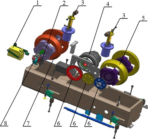
The barrel bore measurement system consists mainly of a signal control box, a bore measurement robot, a computer, and other essential components. The bore measurement robot includes a straight-line power component, a rotary scanning component, and additional necessary elements, as illustrated in Figure 1. The scanning component features a stepping motor and a laser displacement sensor, which are used to collect axial data on the internal bore of the barrel. After the scanning system completes data acquisition for a specific cross-section of the barrel, the straight-line power system drives the robot to move forward or backward, thereby facilitating the acquisition of data for the subsequent cross-section analysis.

Figure 1. Bore measurement robot composition diagram. 1) Laser displacement sensor; 2) Stepper motor; 3) Vertical positioning spring cylinder; 4) Disc motor; 5) Driving wheel; 6) Gear; 7) Driven wheel; 8) Collector ring.
2.2 Laser test principle
Laser triangulation is a measurement method that utilizes the stability of the laser source and the propagation properties of the laser beam [15]. This technique is fundamentally based on the law of optical reflection during the spatial propagation of the beam and the principle of similar triangles, which relies on the geometric relationships formed by triangles. In this method, a laser beam is directed at the target object. When the laser beam strikes the object’s surface, the point of irradiation reflects the laser beam [16].
The laser is positioned in front of the object being measured, and the emitted beam passes through a condenser lens to focus on the surface of the object. However, due to an inherent difficulty in achieving a smooth surface on the object, some of the incident laser beams induce diffuse reflections. The condenser lens helps to concentrate the diffuse reflection onto a single point on an optical sensor. As the measured object’s position changes, the location of the light spot on the sensor also shifts [17, 18]. By analyzing various parameters—such as the angle between the incident and reflected laser beams, the displacement of the light spot, and the distance between the lens and the object—it is possible to calculate the displacement of the object’s surface with a high degree of accuracy.
3 Eccentricity error analysis and calibration model
3.1 Eccentricity error
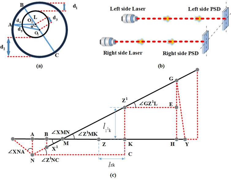
Eccentricity between the center of rotation of the bore inspection robot and the center of the body tube can occur during the testing process due to several factors, such as machining errors, installation errors, and system errors. Figure 2A illustrates how this eccentricity can significantly affect the accuracy of the testing procedure.

Figure 2. Eccentricity error and position calibration model. (A) Eccentricity error, (B) Positional calibration of the dual PSD, (C) Eccentricity error calibration model.
In this setup, the robot is placed in the bore of a standard barrel. The center of the barrel is represented by O1, while the center of rotation of the robot is denoted by O2. Point C marks the furthest distance from the center of rotation O2 to the cross section of the barrel, and point B indicates the nearest distance. The farthest and nearest distances of the sensor’s laser emission port from the barrel are denoted as d1 and d2, respectively. Assuming these locations as the starting points, the distance d3 from O1 to O2 is expressed as Equation 1:
The sensor is connected to the rotating center axis by a mounting bracket. The measurement reference of the sensor is 60 mm, and L denotes the distance from the laser emitting end to the circle centered at O2. With the measured value of the sensor as x, d4 can be expressed as Equation 2:
The cosine theorem can be used to evaluate the distance d5 from the center of the section to a point on the section, which can be expressed as Equation 3:
3.2 Dual PSD-based position calibration model
A Position Sensitive Detector (PSD) is a type of photoelectric distance measuring sensor that employs a light-sensitive element for photoelectric conversion [19]. The fundamental principle behind its operation is as follows: when a beam of light strikes the PSD, a charge is generated at the point of incidence that corresponds to the light energy. The P-type layer is a uniformly integrated resistive layer, and the charge is collected by an electrode through this P-layer. The photocurrent collected by the electrode is inversely proportional to both the point of incidence and the spacing between the electrodes. The schematic diagram of the positional calibration of the dual PSD is shown in Figure 2B.
When the bore measurement robot is properly aligned within the bore, the laser beam strikes the centers of the two PSD target surfaces. The distance between the centers of the two PSDs is denoted as L. The center of the left and the right PSDs are the X-point and Y-point, respectively, with the Z-point as the center of L.
When the bore measurement robot is deflected in the bore, the lateral deflection of the robot’s attitude with respect to the barrel axis can be measured as
Let the position of the laser point on the left PSD be (a1,b1), and the position of the laser point on the right PSD be (a2,b2), then:
In △
In △
In △GMH, we have GH
In △XNA, we have AN
Since:
Therefore, previous equations can be formulated as Equations 5, 6:
where:
In the coordinate system with point X as the origin, let the coordinates of
For a point
4 Three-dimensional reconstruction based on Delaunay's triangular dissection method
The mesh surface reconstruction method offers excellent flexibility, allowing it to effectively handle both simple and complex surfaces. It can be triangulated to meet various fitting requirements, making it a widely used approach in 3D surface reconstruction [20, 21]. One of the techniques employed in this method is Delaunay triangulation [22], which has triangular sections that correspond to a Voronoi diagram.
Let P =
where
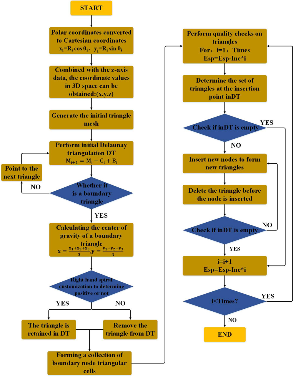
In this paper, a laser displacement sensor is used to scan the bore of a barrel in order to obtain data on the bore profile at a specific cross-section. The scanning process is repeated for multiple cross-sections in the radial direction. Furthermore, the Bowyer-Waston algorithm has been used to perform Delaunay triangulation on the collected data, the schematic is shown in Figure 3.
where Esp is a dynamic variable with an initial value generally slightly larger than the longest side of all current triangles;
Inc denotes: the increment of Esp for a single quality check;
Times represents: the number of times the triangle is quality checked, i.e.,
Times = Int (Esp-Grid_size)/Inc.
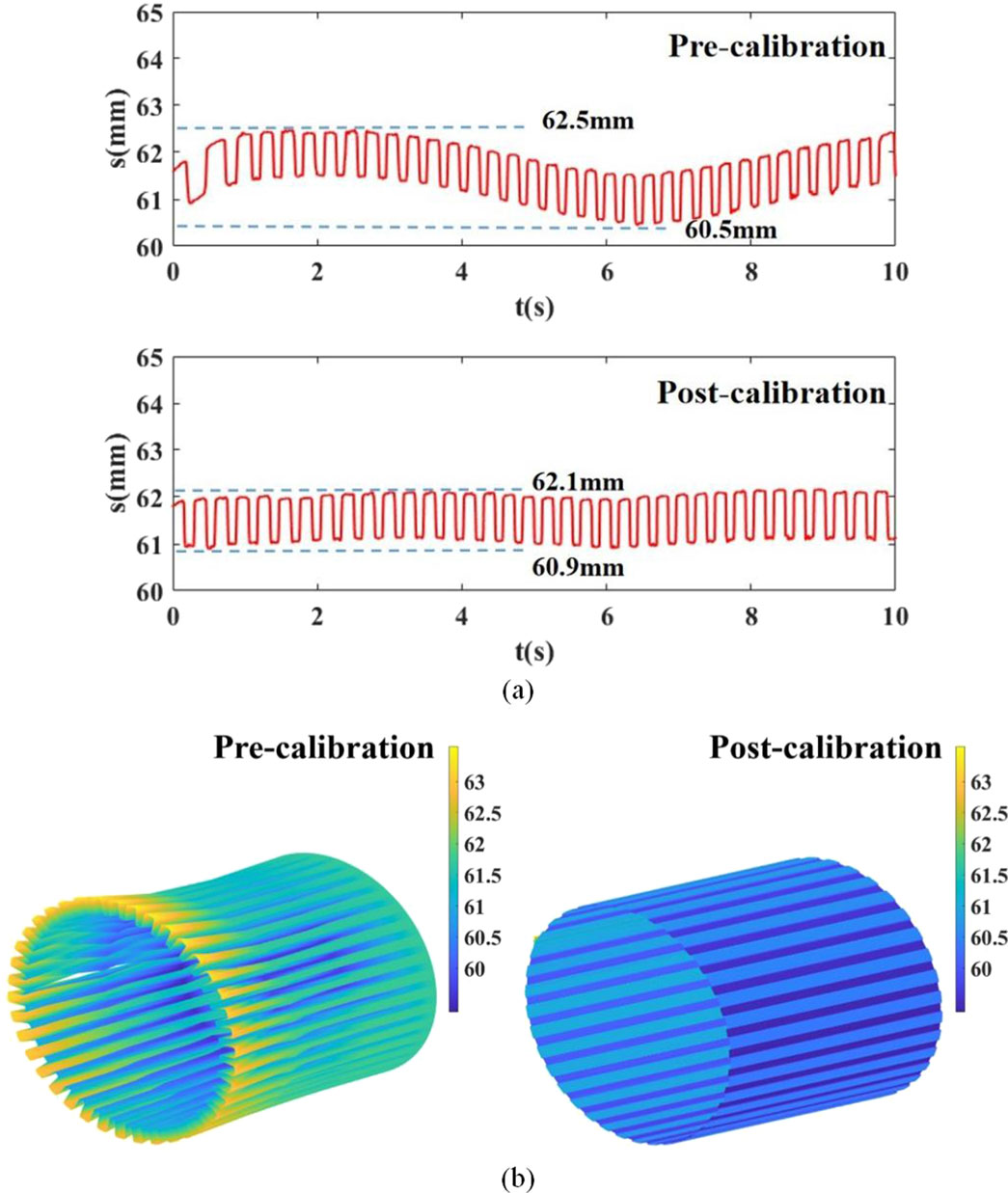
The barrel bore profile curves before and after correction were reconstructed in three dimensions, as shown in Figure 4.

Figure 4. Barrel profile pre and post calibration: (A) Bore profile curve of barrel pre and post calibration, (B) Three-dimensional reconfiguration of the barrel profile of the barrel pre and post Delaunay-based calibration.
As illustrated in Figure 4, the contour curve of the uncorrected barrel exhibited significant irregularities, while the corrected curve demonstrated a notable smoothness. The maximum deviation observed after calibration, compared to the pre calibration measurement, was 0.4 mm. The calibration for the eccentricity error was estimated to be as high as 40%. Utilizing a 3D reconstruction of the barrel bore based on the Delaunay triangular section, it is possible to create a surface model of the bore. The corrected 3D reconstructed model of the bore exhibited significant improvement in its recti-linearity which may bode well for the effective design of artillery barrels.
5 Conclusion
This paper presented a study on measuring and correcting errors in the bore of artillery barrels using laser displacement sensors. The main findings of this study are as follows:
1. This paper employs the laser triangulation testing principle, which is based on a high-precision laser displacement sensor testing method. It presents an analysis of the testing process for the parameters of artillery barrel bores, including the measurement robot testing process, which is susceptible to errors of eccentricity. A rotational model of the robot within the bore of the barrel, along with a dual PSD-based positional compensation model, were developed.
2. The Delaunay triangulation method was utilized to process multiple contour data, enabling the reconstruction of the barrel bore surface into a 3D shape. This technique provided an intuitive representation of the barrel bore’s structure. The contour curve of a barrel was compared pre and post calibration, revealing a smooth contour curve with a maximum calibration degree of 40%. Furthermore, the straightness of the 3D reconstructed model of the barrel bore was significantly improved post calibration. It is expected that the proposed work could harbinger the development of effective bore measurement for artillery barrels, leading to an enhanced performance of the firearm.
Data availability statement
The original contributions presented in the study are included in the article/supplementary material, further inquiries can be directed to the corresponding author.
Author contributions
WJ: Writing–original draft, Methodology. PZ: Conceptualization, Writing–review and editing. XZ: Data curation, Validation, Writing–original draft. ZS: Methodology, Writing–review and editing.
Funding
The author(s) declare that financial support was received for the research, authorship, and/or publication of this article. This research was funded by the Science and Technology on Transient Impact Laboratory (JCKY2023209C003).
Conflict of interest
The authors declare that the research was conducted in the absence of any commercial or financial relationships that could be construed as a potential conflict of interest.
Generative AI statement
The author(s) declare that no Generative AI was used in the creation of this manuscript.
Publisher’s note
All claims expressed in this article are solely those of the authors and do not necessarily represent those of their affiliated organizations, or those of the publisher, the editors and the reviewers. Any product that may be evaluated in this article, or claim that may be made by its manufacturer, is not guaranteed or endorsed by the publisher.
References
1. Wu B, Liu B-j., Zheng J, Wang T, Chen R-g., Chen X-l., et al. Strainbased health monitoring and remaining life prediction of large caliber gun barrel. Measurement (2018) 122:297–311. doi:10.1016/j.measurement.2018.02.040
2. Li B, Quan S, Jin W, Han L, Liu J, He A. Identification of clearance and contact stiffness in a simplified barrel-cradle structure of artillery system. Adv Mech Eng (2015) 7(2):745268. doi:10.1155/2014/745268
3. Li S, Wang L, Yang G. Surface damage evolution of artillery barrel under high-temperature erosion and high-speed impact. Case Stud Therm Eng (2023) 42:102762. doi:10.1016/j.csite.2023.102762
4. Shanmugamani R, Sadique M, Ramamoorthy B. Detection and classification of surface defects of gun barrels using computer vision and machine learning. Measurement (2015) 60:222–30. doi:10.1016/j.measurement.2014.10.009
5. Liu Z, Ma Z, Tu Q, Sun S, Xu L, Ge R, et al. On-line monitoring of flow process in a spout-fluid bed by combining electrical tomography and high-speed CCD camera. Chem Eng Sci (2022) 267:118332. doi:10.1016/j.ces.2022.118332
6. Fu X, Zhang Y, Zhang W, Li Q, Kong T. Research on the size of ring forgings based on image detection and point cloud data matching method. Int J Adv Manufacturing Technology (2022) 119(3):1725–35. doi:10.1007/s00170-021-08268-9
7. Medina R, Gayubo F, González-Rodrigo LM, Olmedo D, Gómez-García-Bermejo J, Zalama E, et al. Automated visual classification of frequent defects in flat steel coils. Int J Adv Manufacturing Technology (2011) 57(9-12):1087–97. doi:10.1007/s00170-011-3352-0
8. Huang FS, Chen L. CCD camera calibration technology based on the translation of coordinate measuring machine. Appl Mech Mater (2014) 3252(568). doi:10.4028/www.scientific.net/AMM.568-570.320
9. Bracun D, Selak L, Klobcar D, Markucic D. Intrusive laser triangulation method for non-contact detection of voids in translucent composites. NDT and E Int Independent Nondestructive Test Eval (2024) 145. doi:10.1016/j.ndteint.2024.103143
10. Shanmugamani R, Sadique M, Ramamoorthy B. Detection and classification of surface defects of gun barrels using computer visionand machine learning. Measurement (2015) 60:222–30. doi:10.1016/j.measurement.2014.10.009
11. Moritz R, rnChristian W. Frey. Rotating optical geometry sensor for inner pipesurface reconstruction Image processing. In: Machine vision applications III (2010).
12. Long X, Chen Q, Gao X, Chen S. Improvement of SURF feature image registration algorithm based on cluster analysis. (2014).
13. Medina R, Gayubo F, González-Rodrigo LM, Olmedo D, Gómez-García-Bermejo J, Zalama E, et al. Automated visual classification of frequent defects in flat steel coils. Int J Adv Manufacturing Technology (2011) 57(9-12):1087–97. doi:10.1007/s00170-011-3352-0
14. Shen C, Zhou K-dong, Lu Y, Jun-song L. Modeling and simulation of bullet-barrel interaction process for the damaged gun barrel. Defence Technology (2019) 15:972–86. doi:10.1016/j.dt.2019.07.009
15. Wang Y, Zhou P, Yao CW, Wang HY, Lin B. Development of a novel multi-line laser triangulation scanning system based on the rotary diffraction grating. Measurement (2024) 225. doi:10.1016/j.measurement.2023.113988
16. Wu C, Chen B. An automatic measurement system for the wall thickness of corrugated plate based on laser triangulation method. Adv Eng Inform (2023) 55:101814. doi:10.1016/j.aei.2022.101814
17. Hua L, Lu Y, Deng J, Shi Z, Shen D. 3D reconstruction of concrete defects using optical laser triangulation and modified spacetime analysis. Automation in Construction (2022) 142:104469. doi:10.1016/j.autcon.2022.104469
18. Nan Z, Tao W, Zhao H, Lv N. A fast laser adjustment-based laser triangulation displacement sensor for dynamic measurement of a dispensing robot. Appl Sci (2020) 10(21):7412. doi:10.3390/app10217412
19. David R-N, José L-G, Ignacio BM, Gardel-Vicente A, Tsirigotis G. Analysis and calibration of sources of electronic error in PSD sensor response. Sensors (2016) 16(5):619. doi:10.3390/s16050619
20. Jung S, Lee Y-S, Lee Y, Lee K. 3D reconstruction using 3D registration-based ToF-stereo fusion. Sensors (2022) 22:8369. doi:10.3390/s22218369
21. Sun H, Wang S, Bai J, Zhang J, Huang J, Zhou X, et al. Confocal laser scanning and 3D reconstruction methods for the subsurface damage of polished optics. Opt Lasers Eng (2021) 136:106315. doi:10.1016/j.optlaseng.2020.106315
Keywords: high precision laser, barrel bore measurement, eccentricity error calibration, 3D reconstruction, delaunay triangular sectional interpolation
Citation: Jin W, Zhang P, Zhang X and Shi Z (2025) On the measurement of the barrel bore based on laser scanning and eccentricity correction. Front. Phys. 13:1545456. doi: 10.3389/fphy.2025.1545456
Received: 15 December 2024; Accepted: 06 January 2025;
Published: 22 January 2025.
Edited by:
Zhaohong Liu, Hebei University of Technology, ChinaReviewed by:
Jinxiang Wang, Nanjing University of Science and Technology, ChinaHuilong Pi, Hunan University, China
Guohua Wei, Beijing Institute of Technology, China
Copyright © 2025 Jin, Zhang, Zhang and Shi. This is an open-access article distributed under the terms of the Creative Commons Attribution License (CC BY). The use, distribution or reproduction in other forums is permitted, provided the original author(s) and the copyright owner(s) are credited and that the original publication in this journal is cited, in accordance with accepted academic practice. No use, distribution or reproduction is permitted which does not comply with these terms.
*Correspondence: Wei Jin, YjIwMjMwMTE2QHN0Lm51Yy5lZHUuY24=
 Wei Jin
 Pengjun Zhang
 Xinyi Zhang