 Tianyang Xu
 Hongjian Jia1
95% of researchers rate our articles as excellent or good
Learn more about the work of our research integrity team to safeguard the quality of each article we publish.
Find out more
ORIGINAL RESEARCH article
Front. Phys. , 06 February 2025
Sec. Physical Acoustics and Ultrasonics
Volume 13 - 2025 | https://doi.org/10.3389/fphy.2025.1541799
Underwater small targets typically exhibit non-centrosymmetric geometries, resulting in a highly spatially inhomogeneous acoustic scattering field under active sonar detection. Addressing these challenges, this paper takes the hemispherical cylindrical shell as the research object, considers the angle continuity implied in the echo characteristics, and proposes a cluster-driven research method for the non-uniform characteristics of the target echo angles. First, the target echo features are extracted and feature vectors are constructed. Secondly, the t-distributed stochastic neighbor embedding algorithm is employed to improve the internal connection of the feature vector in the low-dimensional feature space and to construct the visualized feature space. Finally, the implicit angular relationship between echo features is extracted under unsupervised conditions by cluster analysis. The reconstructed local geometric structures corresponding to different categories demonstrate that the method effectively segments the angular intervals of local target structures based on their natural acoustic scattering characteristics. The study overcomes the inherent subjectivity of traditional methods for dividing angular intervals of target echoes, providing a more objective foundation for segmenting and analyzing the target’s geometrical structure.
Underwater target detection and recognition technology is currently one of the hotspots in marine acoustics research both domestically and internationally, as well as a recognized challenge in the academic community [1]. When underwater targets are acoustically passive, active sonar detection methods are effective means for detecting stealthy targets. However, the small size, weak acoustic signatures, and high level of sophistication of underwater small targets present numerous challenges for detection efforts. The acoustic scattering echoes of underwater targets are the main source of information for active sonar [2]. The scattering characteristics of targets are influenced by various factors such as target structure, size, material, and external environment, which serve as effective bases for underwater target detection and recognition. Underwater small targets generally have non-centrally symmetric geometric shapes, thus, the target acoustic scattering field exhibits high spatial non-uniformity under active sonar detection conditions. With the improvement of computational performance and experimental capabilities, calculating and collecting target scattering signals at different angles of sound wave incidence have become essential methods for studying the omnidirectional acoustic scattering characteristics of targets [3, 4].
The target scattering characteristics serve as important foundations for marine active sonar detection of underwater targets, acting as a bridge between scattering theory and echo signal characteristics [5]. Exploring the physical mechanisms behind target scattering formation and identifying the relationship between scattering signal characteristics and target physical properties are crucial for classifying and identifying underwater targets of different states and categories. Target scattering theory mainly discusses the scattering acoustic field generated by the interaction between sound waves and targets, essentially involving all physical phenomena related to fluid and solid interface surface wave motion, vibration, and sound coupling [6]. The motion of sound waves in the physical field can be summarized by mathematical physics problems described by wave equations and boundary conditions [7]. Rigorous solutions of scattering theory provide the physical meaning of target scattering and its causes, serving as the theoretical basis for the numerical calculation of scattering fields. Based on scattering theory, the scattering components of cylindrical shell target models exhibit interference in the frequency domain. Since these components vary continuously with the incident angle of sound waves, the frequency domain interference patterns are correlated with the incidence angle. Therefore, a method utilizing relatively low-frequency acoustic signals for structural acoustic discrimination is proposed. This method involves analyzing the variation characteristics of target echo components in the angle-frequency spectrum, enabling the intuitive identification of different signal components [8,9]. Houston [10] studied the relationship between the acoustic scattering characteristics of cylindrical targets such as gas cylinders and water-filled oil barrels and the angle change. Structural information of targets can be observed in the low-frequency range, providing a new research mechanism for marine target acoustic structure identification.
The US Underwater Target Structure Laboratory conducted the UXO (Unexploded Ordnance) project targeting marine unexploded ordnance, precisely measuring the acoustic structure of marine targets and obtaining comprehensive acoustic scattering characteristics, which provides important foundations for marine target classification and identification. Bucaro [11] conducted 360° omnidirectional broadband signal acoustic scattering measurements on two types of mortar shells, shells, and rockets, comparing them with the acoustic characteristics of non-artificial targets such as stones. The transmitted signal frequency band adapted was 1 kHz–140 kHz, covering the acoustic frequency range with wavelengths comparable to the target size. Researchers mounted transducers on a circular track, placing targets at the center of the circular track, and realized omnidirectional target structural acoustic measurements by moving the transducer position. Researchers plotted angle-frequency spectra of target echoes, intuitively describing the relationship between frequency domain scattering characteristics and the incident angle of sound waves. Additionally, the technique of forward scattering for underwater target detection was investigated [12]. Experimental designs obtained comprehensive acoustic scattering characteristics of targets under different environments. Measurements of the frequency characteristics of target scattering signals under different incident angles were conducted in free-field, seabed, and semi-buried environments. Results indicated that forward scattering waves exhibited higher energy levels than backward scattering echoes, and the attenuation in the semi-buried condition was weaker than that of backward scattering echoes, aligning with the radar target detection. This method can effectively facilitate target detection in complex marine environments.
Fan [13, 14] utilized a high-resolution broadband transceiver array system to extract the resonance frequency range of targets based on numerical simulation results and measured the acoustic scattering characteristics of hemispherical finite cylindrical shell targets under free-field conditions using single-frequency pulses and broadband linear frequency modulation pulses. The measurement results were highly consistent with theoretical calculations, explaining the formation of bowl-shaped stripes in the angle-frequency spectrum. For internally ribbed cylindrical shell targets, the study combined experiments to investigate the backward scattering characteristics elucidated the features observed in the angle-frequency spectrum through the interaction between shell resonances and scattering waves. Additionally, it provided a theoretical analysis of interference fringes resulting from specular reflection and shell structure scattering. Li [15] conducted a study on the acoustic scattering characteristics of hemispherical cylindrical target models. They comprehensively measured the acoustic scattering characteristics of targets in free-field experimental environments using broadband-modulated signals and investigated the correlation between target acoustic scattering characteristics and the incident angle of sound waves. By employing the target echo highlight model, they separated echo signals under conditions of linear frequency modulation transmission, extracted the elastic scattering components of targets, and applied them to target identification. Additionally, for locally filled hemispherical cylinders, experiments were conducted to perform 360° acoustic scattering measurements under transceiver conditions. The mechanisms of geometric echoes and various elastic wave components in target scattering signals were elucidated using numerical calculation methods [16].
Existing research on the omnidirectional acoustic scattering characteristics of hemispherical cylindrical shell targets reveals that both geometric and elastic acoustic scattering features exhibit non-uniform variations with the incident angle of sound waves. Geometric scattering echoes are directly influenced by the external geometric contour structure of the target. Components such as the cylinder body, edges, and crown impact the distribution range and variation pattern of echoes with angle, while elastic scattering echoes are closely related to the material properties of the target [17]. In the frequency domain, the influence of cylinder length and shell thickness ratio on the interval of elastic resonance peaks is relatively weak, serving as effective features for identifying target materials. However, the resonance peak interval is also related to the incident angle, and different materials may have the same resonance peak interval at different angles [18]. Therefore, for the studied target models, the echo feature information obtained at different detection angles is different, and relying solely on echo information collected at a single incident angle is not reliable. It is necessary to comprehensively process the omnidirectional acoustic scattering characteristics of targets. Xu [19] employed the WVD-Hough transform to extract the number, strength, and phase difference of target highlights at different angles, studying the angle variation characteristics of geometric acoustic scattering of marine targets. However, the analysis did not consider the impact of elastic acoustic scattering echoes. Li [20] investigated a deep learning-driven angle recognition model for marine target echoes, which is capable of identifying target poses under different angles of sound wave incidence. However, the aforementioned research framework constructs a deep neural network under supervised conditions and employs a uniform segmentation method to partition the whole echo feature set. Nevertheless, for non-centrally symmetric underwater targets, the echo features vary non-uniformly with angle. Thus, the uniform segmentation of the omnidirectional target echo dataset lacks a physical basis and fails to reflect the local geometric shape variation characteristics of the targets.
To address the spatial non-uniformity issue of the acoustic scattering field of underwater non-centrally symmetric targets, this paper will establish a feature space based on the relationship between target acoustic scattering characteristics and incident angles of sound waves. We will investigate the clustering properties of echo features at different angles in the feature space. Clustering [21], a classic unsupervised learning algorithm, fundamentally organizes sample data into categories by exploring and inducing the intrinsic structure of the data by utilizing similarities among samples. The ultimate goal of clustering is to make objects in the same category similar and objects in different categories different. The greater the similarity of sample points within the same category, the smaller the similarity between different categories, and the better the clustering effect. At present, the widely studied clustering algorithms can be roughly divided into the following categories [22]: hierarchical clustering, density-based clustering, prototype-based clustering and partition-based clustering. Among these, K-means clustering, a widely used partition-based clustering method, is selected for its simplicity, efficiency, and effectiveness in handling large datasets and well-defined categories. It is an iterative clustering analysis algorithm that initially partitions sample data into K groups and randomly selects corresponding cluster centers as the centroids of each subgroup. Subsequently, it calculates the distance between each sample and these subgroup centroids, assigning samples to the nearest centroid and forming clusters. Throughout the iterative process, centroids are recalculated based on existing objects in the cluster until termination conditions are met. The choice of K-means clustering in this study is motivated by its ability to partition data into distinct clusters based on feature similarity, which is crucial for analyzing the angular clustering characteristics of echo features. Additionally, K-means allows iterative refinement of cluster assignments, making it suitable for observing and adjusting the angular intervals associated with the target’s geometric structures. In this paper, the clustering approach is utilized as a technology tool to analyze the angular clustering characteristics of echo features in feature space. K-means clustering will be employed to extract the implicit angular continuity rules among target echo features, and we will non-uniformly partition the omnidirectional target echoes based on the clustering results. The primary aim of this study is to address the subjectivity inherent in existing methods for dividing the angular intervals of target echoes. By leveraging the implicit angular relationships between echo features, the study provides a more objective basis for segmenting the target’s structural components.
A finite element numerical simulation model was developed to explore the scattering characteristics of a stainless steel hemispherical cylindrical shell target filled with air, aiming for a deeper understanding of its scattering characteristics. This model computed the omnidirectional backscattering field of the target, as depicted in Figure 1. The hemispherical cylindrical shell structure was constructed by incorporating a hemispherical shell into the finite cylindrical shell. The total length of the target is 2.1 m, with an outer diameter of the hemispherical part measuring 0.53 m and a shell thickness of 8 mm. Both the target shell and the surrounding water body are discretized using free triangular meshes. Both the target shell and the surrounding water body are discretized using free triangular meshes. The maximum element size is set to 0.003 m, which ensures it is less than one-sixth of the wavelength corresponding to the highest calculation frequency of 40 kHz
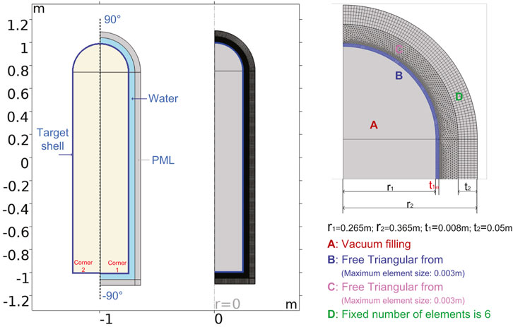
Figure 1. The finite element model of hemispherical cylindrical shell.
To comprehensively investigate the scattering characteristics of the target model across the mid-to-high frequency range, the simulation frequency range was set from 10 kHz to 40 kHz, with a frequency interval of 50 Hz. Unlike the fully symmetric properties of spherical targets, the backscattering characteristics of hemispherical cylindrical shell targets exhibit variability with the incident angle of sound waves, indicating a notable spatial non-uniformity with angle variation. Hence, computing the omnidirectional scattering field of the target model becomes imperative. Given that the hemispherical cylindrical shell target represents an axially symmetric structure, the incident plane wave angle was set within the range from −90° to 90°, covering the omnidirectional scattering field. The incident sound wave was configured as a plane wave, with the receiver position placed at 50 m to ensure the far-field conditions. Figure 2 illustrates the angle-delay structure of the target scattering echoes within the range from −90° to 90°.
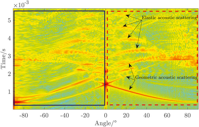
Figure 2. The angle-time delay structure of the hemispherical cylindrical shell.
The calculation results indicate that the spatial distribution of the target acoustic scattering field varies with the incident angle of sound waves, owing to the non-centrally symmetric characteristics of the target’s geometric shape. In the time domain, the initial echo component is geometric scattering generated from the target’s outer surface, succeeded by elastic scattering echoes resulting from the target’s elastic response. Geometric scattering echoes span the entire observed angle range, whereas elastic scattering echoes appear within a specific angle span. Within the range of −90°–0° (solid rectangular box), the first arriving echo emerges from edge and corner scattering, generated by the edges of the cylinder base. Conversely, within the 0°–90° range (dashed rectangular box), the initial geometric scattering echo arises from the specular reflection echo generated by the hemispherical shell part, exhibiting markedly higher echo intensity than the edge scattering echo. Subsequent echoes following the geometric scattering echoes comprise elastic scattering echoes, predominantly distributed within the −56°–52° range. The angle span of elastic scattering echoes gradually diminishes with increasing circumferential turns, accompanied by a gradual energy attenuation. Due to the elastic properties of the target material, different frequency components of elastic scattering echoes propagate at varying phase velocities, resulting in a degree of dispersion. Consequently, compared to geometric scattering echoes, the duration of elastic scattering echoes is broadened to some extent. The hemispherical shell introduces a certain asymmetry in the omnidirectional backscattering angle-delay structure. However, due to the relatively small radius of the spherical shell part compared to the length of the cylindrical body
For underwater target echo scattering, the geometric scattering components primarily hinge on the target shape. Leveraging geometric scattering components can estimate the target shape and size. Specifically, specular reflection echoes can be approximated as delayed replicas relative to the transmitted signal, thereby preserving consistency with the signal properties of the transmitted signal. Therefore, emphasis is commonly placed on the temporal structure of echo components in the study of geometric scattering echoes, with subsequent focus directed toward reconstructing the target geometric shape through the temporal structure.
The highlight model is an engineering approximation model that describes the distribution of real geometric echo highlights on the target, and effective geometric highlight components present on the target can be identified through the highlight model. Based on the target geometric structural parameters, the temporal structure of the geometric scattering echoes within the range of −90°–90° is calculated, and compared with the results from the finite element calculation. The comparative result is illustrated in Figure 3.
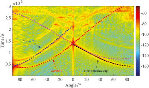
Figure 3. The angle-time delay structure of geometric acoustic scattering of the hemispherical cylindrical shell.
When the incident angle of the sound wave is 0°, the first echo detected by the hydrophone is the reflection echo generated by the cylindrical body, characterized by its robust amplitude owing to its expansive effective radiation area. Within the incident angle range of 0°–90°, the echo reaching the hydrophone is the specular reflection echo produced by the hemispherical cap highlight of the target. This specular reflection echo can be explained by the concept of “Fresnel zones” in geometric optics. These reflection waves originating from discontinuously smooth surfaces constitute the sum of reflections from all “First Fresnel” zones (highlight zones) situated at a radial distance of 1/4 wavelength from the normal direction and the incident direction, with the intensity of each highlight contingent upon the surface curvature at that point. Based on the target geometric parameters, where the radius
According to the temporal structure of target geometric echoes, tomographic imaging techniques can be adopted to reconstruct the geometric profile of the target model. Tomographic imaging [23, 24], also referred to as computer-assisted tomography, operates by reconstructing the two-dimensional geometric shape and internal structural features of a three-dimensional object through the one-dimensional projection data processing collected from various angles. Marine acoustic imaging mainly relies on high-resolution sonar imaging systems, which typically consist of wideband beamforming transducers and two-dimensional receiving hydrophone arrays. These systems can generate high-resolution three-dimensional sonar images from a single received echo through near-field focused beamforming. This section will apply tomographic imaging techniques for marine active sonar detection and echo imaging based on a transceiver sonar system.
In a transceiver sonar system where the transmitted and received transducers are colocated, echoes are generated when the transmitted sound wave illuminates the target object and some of these echoes are reflected to the received transducer. Assuming an ideal scenario where the incident sound wave behaves like a
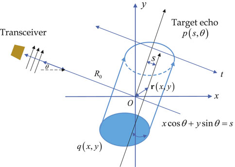
Figure 4. Schematic diagram of echo tomography reconstruction of underwater targets geometric features.
Through Eqaution 1, a mathematical correlation between the object echo, represented by
Where
Performing a two-dimensional spatial Fourier transform on
Let
Equation 5 represents the Fourier central slice theorem.
Based on the analysis of the temporal structure of geometric acoustic scattering, the omnidirectional geometric structure of the studied hemispherical cylinder shell is successfully reconstructed, as depicted in Figure 5. The result indicates that both the hemispherical and cylindrical components of the target are accurately reconstructed, aligning well with the specified dimensions we set. However, certain disturbances are evident beyond the geometric boundaries of the object, particularly noticeable at the bottom edges and the junction between the hemispherical crown and the cylindrical body. It is noteworthy that the reconstruction quality of the target structure, which generates specular reflection echoes, is superior, whereas the results for edges and junctions exhibit certain discrepancies. This discrepancy can be attributed to the smaller curvature radius at the edges, leading to rapid surface changes that cause scattering waves to diverge more, thereby affecting the reconstruction process to some degree. Nevertheless, overall, the omnidirectional geometric outer structure of the target is satisfactorily reconstructed.
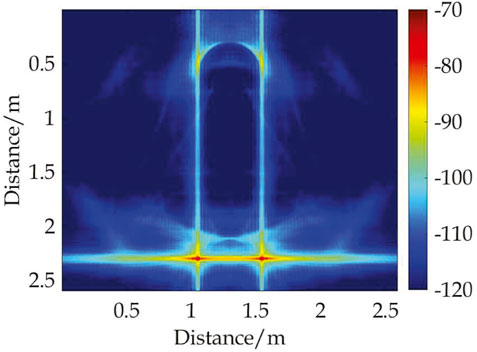
Figure 5. Echo tomography of the hemispherical cylindrical shell.
For a hemispherical cylindrical shell, the non-centrally symmetric property of the target’s geometric structure results in varied echo properties at different incident angles of the sound wave. However, at the same time, the target also belongs to a regular geometric structure, implying that the echo characteristics of adjacent angles exhibit a certain correlation. Therefore, when studying the angle-dependent characteristics of target echoes, it becomes essential to consider the implicit angular continuity within these echo features. To address this, this section proposes the utilization of clustering-driven methods to analyze the non-uniform angle characteristics of target echo features. The process involves three steps: (1) Extracting target echo features and constructing feature vectors. (2) Utilizing nonlinear dimensionality reduction algorithms to visualize high-dimensional feature spaces. (3) Clustering the whole echo features in the feature space to establish correlations between echo features and angles. The processing workflow is illustrated in Figure 6.
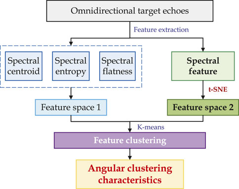
Figure 6. The research process of the cluster-driven angle characteristic.
To investigate the acoustic scattering characteristics of practical targets, experiments were conducted on a stainless steel hemispherical cylindrical shell filled with air in an anechoic water tank. This environment effectively mitigates external disturbances such as noise and reverberation, simulating conditions akin to underwater free-field sound fields. The anechoic pool has dimensions of 25 m
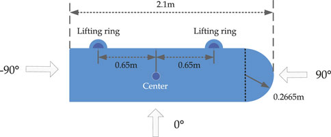
Figure 7. The experiment target model structure.
Under the marine active sonar detection background, the target acoustic scattering echo is greatly influenced by the change of the transmitted signal, leading to diverse characteristics in target echo signals. In experimental measurements, the number and intensity of elastic scattering echoes often deviate significantly from numerical computation results in the time domain. Consequently, both time-domain waveforms and time-frequency spectrograms of target acoustic scattering echoes lack universality. However, existing studies on target elastic resonance characteristics reveal that experimentally measured targets demonstrate considerable consistency with theoretical research results in the frequency domain. Moreover, the intervals between elastic resonance peaks serve as effective features for characterizing target material properties. Hence, establishing a feature space based on the spectral features of target acoustic scattering echoes and subsequently performing angle clustering yield higher reliability.
According to the processing workflow depicted in Figure 6, two methods will be employed to construct feature vectors. The first method involves extracting typical spectral features for feature vector construction. When the dimensionality of the feature vector is two-dimensional or three-dimensional, it offers a more intuitive understanding of the feature distribution in the feature space. Consequently, the paper selects three typical spectral features: spectral centroid (SC), spectral entropy (SE), and spectral flatness (SF), to construct feature vectors. These features originate from the auditory perception field, the characteristics of received sound signals can be described utilizing the human ear auditory model. Spectral centroid represents the centroid of the signal spectrum, portraying the “brightness” of the sound signal by indicating the fundamental frequency value of the signal spectrum. Spectral entropy quantifies the flatness of the signal spectrum by computing the Shannon entropy of the frequency-domain signal, utilizing the disorder of the spectrum amplitude distribution as a measure of signal certainty. Spectral flatness primarily quantifies the timbre of the sound signal, describing the number of peaks or resonant structures in the spectrum. Given the significant differences in the magnitudes of these three features, data standardization is adapted before feature vector construction.
The second method directly utilizes spectral features as feature vectors. However, since clustering tasks typically require low-dimensional spaces for analysis, directly using spectral features to construct feature vectors would result in high-dimensional feature vectors, which are not conducive to visualization. Therefore, dimensionality reduction of spectral features becomes necessary. Initially, linear dimensionality reduction methods are considered for reducing the dimensionality of spectral features. Principal Component Analysis (PCA) stands out as one of the most widely used linear dimensionality reduction methods. It offers advantages such as fast computation speed, low space occupation, and the ability to merge similar features during the dimensionality reduction process, which helps prevent overfitting. However, PCA has limitations—it cannot capture complex polynomial relationships between features, potentially leading to underfitting when dealing with complex datasets.
To address the aforementioned challenges, Matten and others proposed the utilization of t-distributed Stochastic Neighbor Embedding (t-SNE) to uncover the intrinsic relationships between data points. t-SNE is a nonlinear dimensionality reduction algorithm derived from the SNE algorithm, tailored for reducing high-dimensional data to two or three dimensions, thus facilitating the creation of low-dimensional data conducive to visualization. SNE establishes the relationship between data points and probability distributions through affine transformation, converting Euclidean distances into conditional probabilities to characterize the similarity between points. It begins by constructing a probability distribution of high-dimensional objects, allowing similar objects to have higher selection probabilities. Subsequently, it constructs a probability distribution of points in low-dimensional space to maximize their similarity. To mitigate the “crowding problem” encountered during the optimization process of the SNE algorithm, symmetric SNE simplifies the gradient formula and utilizes the t-distribution instead of the Gaussian distribution to represent the similarity between points in low-dimensional space, resulting in the t-SNE algorithm. This algorithm generates a larger gradient with a small distance, causing dissimilar points to repel each other. Moreover, the repulsion distance is bounded by the denominator of the gradient, preventing dissimilar points from being excessively distant. Therefore, this section will employ the t-SNE algorithm to perform dimensionality reduction on spectral features, reducing the dimensionality of the spectral features to three dimensions, and constructing feature vectors accordingly.
According to the target axial symmetry, we selected 900 sets of angle-continuous echo data ranging from −90.0° to 90.0° as samples, with an angle increment of 0.2° referred to Figure 1. The lifting rings acted as main highlights, showing notable energy in the received echoes. Since the echoes from the lifting rings were spread across the entire angle span without distinctive clustering characteristics, they were removed by data preprocessing, thereby retaining only the acoustic scattering echo components of the hemispherical-capped cylindrical shell target itself. Feature extraction was performed on the separated echo signals and feature spaces were sequentially constructed, illustrated in Figure 8. To distinguish between them, the feature space comprising spectral centroid, spectral entropy, and spectral flatness was denoted as feature space 1, while the space formed through the dimensionality reduction of spectral features was termed feature space 2. The results depicted in Figure 8A reveal that in feature space 1, the sample distribution appears scattered, failing to intuitively represent the angle correlation among samples. Conversely, the effect of constructing feature vectors using the second method surpasses that of the first. Compared with feature space 2, the physical meaning of feature space 1 is clearer, but SC, SE, and SF cannot effectively represent the angle information to be studied in this paper. Throughout the construction of feature spaces, it was observed that manually selecting features resulted in a loss of angle information between samples, thereby weakening the angle correlation within echo features, which is also a problem in traditional feature engineering. In feature space 2, the sample distribution exhibits a discernible regularity and continuity. Although the physical meaning of feature space 2 is not clear, the angle continuity feature information implied between samples is better preserved, which is also the key to further analyzing echo angular clustering characteristics in this paper.
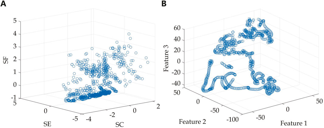
Figure 8. Feature space of omnidirectional target echoes. (A) Feature space 1 (SC, SE, and SF). (B) Feature space 2 (spectral features after dimensionality reduction).
For the hemispherical cylindrical shell, K-means clustering is adopted to study angular clustering characteristics of omnidirectional target echo features and extract the implicit angle continuity patterns among samples. Excluding the echo components from the lifting rings, the target model displays three distinct highlight components: the hemispherical cap, the cylindrical body in the abeam transverse direction, and the bottom end face. Thus, the initial number of clusters is set to 3, and clustering is performed in two feature spaces. The iterative process continues until convergence is achieved, where the cluster assignments no longer change significantly. The final centroid positions are marked and visualized with red circles in Figures 9A, 10A. The analysis reveals that, in feature space 1, three primary categories are identifiable. However, Categories 2 and 3 contain numerous scattered points, which fail to exhibit angular continuity among samples, leading to less stable clustering results. In contrast, the clustering results in feature space 2 demonstrate three well-defined categories with no abrupt outliers between them. Figures 9B, 10B illustrate how the samples are grouped into their respective categories in the two feature spaces. The horizontal axis represents the number of samples in the dataset, while the vertical axis corresponds to the three categories identified by the K-means algorithm. Category 1 corresponds to the angle range of −90.0°–6.6°; Category 2 encompasses angles from 11.2° to 53.8°; while Category 3 comprises two angle ranges, labeled as
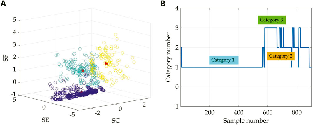
Figure 9. Clustering number is three. (A) Feature space 1 (SC, SE, and SF). (B) Relationship between samples and their respective categories after clustering.
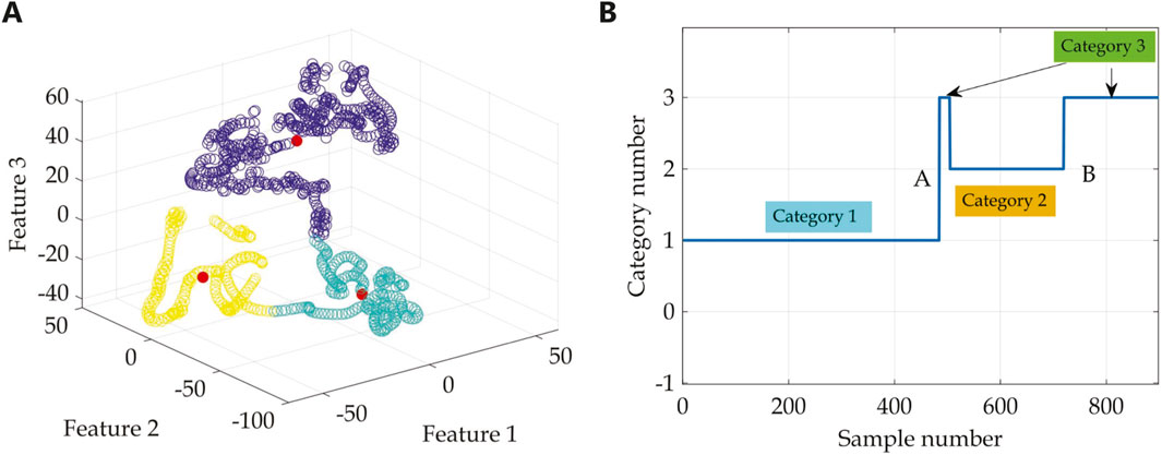
Figure 10. Clustering number is three. (A) Feature space 2 (spectral features after dimensionality reduction). (B) Relationship between samples and their respective categories after clustering.
To provide a more intuitive analysis of the physical significance of the angular clustering results, tomography imaging was employed to reconstruct the geometric structures corresponding to Categories 1, 2, and 3, as shown in Figure 11 based on the clustering results depicted in Figure 10B. The analysis reveals that due to the clustering number being set to 3 (the value is small), the subdivision of angles is not finely tuned. Category 1 mainly corresponds to the hemispherical cap and cylindrical body of the target model; Category 2 primarily aligns with the corners of the bottom edge; Category 3 presents a more complex result, representing two structure components. According to the local magnification results in Figure 11C, Category 3 corresponds to the bottom end face of the cylinder within angle range
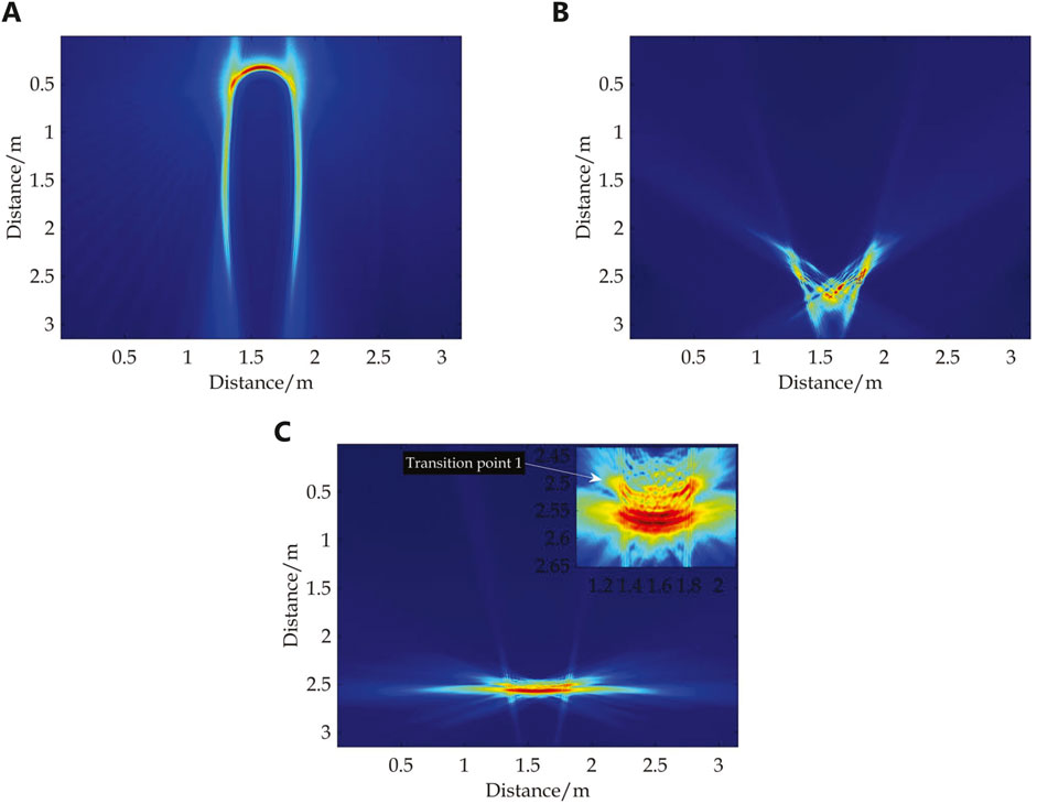
Figure 11. Echo tomography of the categories in Figure 9B. (A) Category 1. (B) Category 2. (C) Category 3.
Setting the number of clusters to 4 and conducting clustering analysis in feature space two yields the results depicted in Figure 12. The analysis indicates that introducing a new category did not impact the results of Categories 1 and 2. Category 4 represents a further refinement based on the clustering results of Category 3. Specifically, Category 3 still corresponds to two angle ranges, with the results for angle range
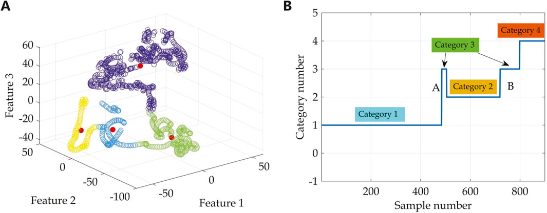
Figure 12. Clustering number is four. (A) Feature space 2 (spectral features after dimensionality reduction). (B) Relationship between samples and their respective categories after clustering.
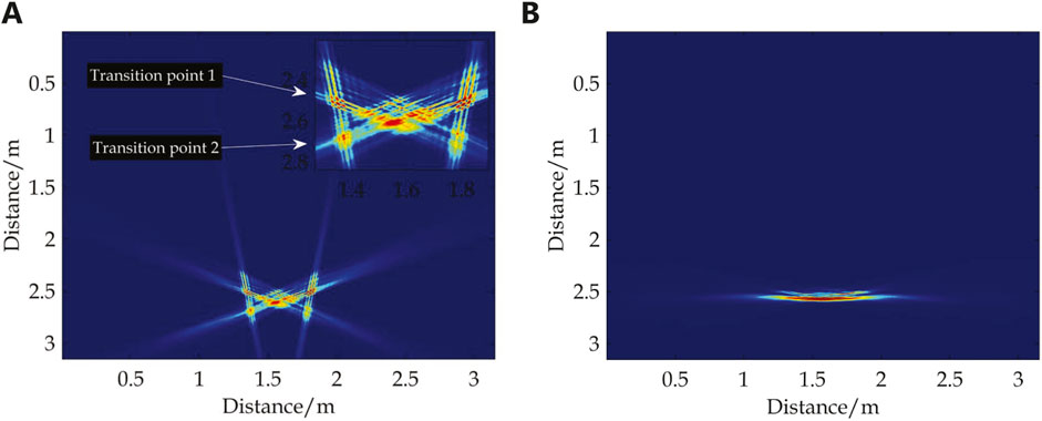
Figure 13. Echo tomography of the categories in Figure 12B. (A) Category 3. (B) Category 4.
Combining the clustering results with cluster numbers 3 and 4, a more detailed study and analysis of the angular clustering characteristics at the bottom edge corner were conducted. However, Category 1 still occupies approximately more than half of the angle range. Therefore, the cluster number was increased to 5 to achieve a finer refinement of the angle ranges for Category 1. The processing result is presented in Figure 14. The results indicate that the clustering results for Categories 2 to 4 have stabilized and remain unchanged, while Category 5 represents a new category separated from Category 1. At this point, Category 1 corresponds to the angle range of −90.0° to −8.4°, and Category 5 corresponds to the angle range of −8.6°–6.6°. The geometric structures corresponding to the new Categories 1 and 5 are depicted in Figure 15. It can be observed that Category 1 mainly corresponds to the hemispherical cap part of the target, while Category 5 corresponds to the cylindrical body. Compared to Figure 11A, Category 5 further refines the angle range of the cylindrical body. The geometric structure of the hemispherical cap is spherical, displaying relatively fewer variations in echo characteristics. Therefore, despite occupying approximately 90.0° of the angle range, the clustering results of Category 1 remain relatively stable. If further refinement of Category 1 is required, the number of clusters can be increased to subdivide the hemispherical cap region.

Figure 14. Clustering number is five. (A) Feature space 2 (spectral features after dimensionality reduction). (B) Relationship between samples and their respective categories after clustering.
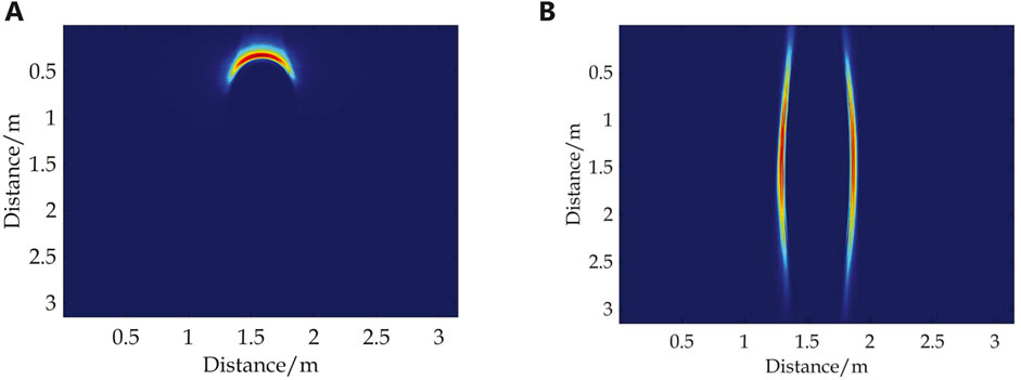
Figure 15. Echo tomography of the categories in Figure 14B. (A) Category 1. (B) Category 5.
A summary of the angle ranges and target structures corresponding to different categories under different clustering numbers is presented in Table 1. Since the geometric structure of the hemispherical cylindrical shell target studied in this paper is relatively regular, it is already reasonable to divide the target structure when the clustering number is 5 or 6. For targets with larger geometric dimensions and more complex structures, further refinement of the angle ranges and target structures can be achieved by increasing the clustering number.
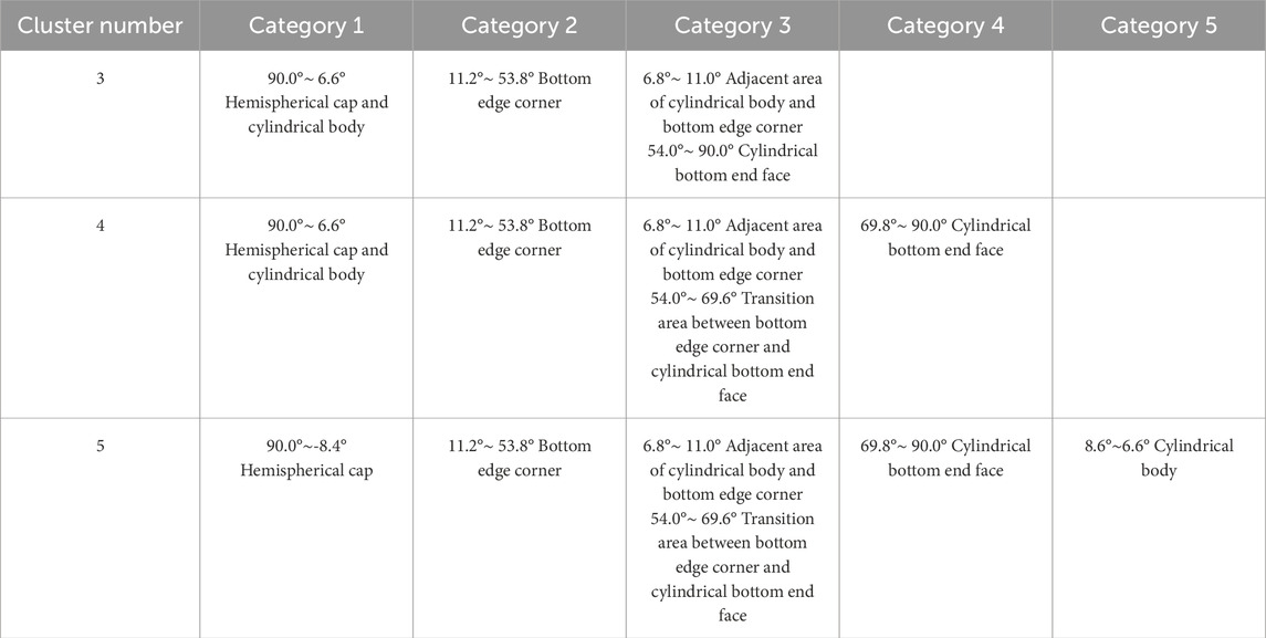
Table 1. Angle range and target structure of different categories.
The study addressed the spatial non-uniformity in the target acoustic scattering field and investigated the angular clustering patterns of omnidirectional target echoes. Spectral features of the target acoustic scattering echoes were extracted to form feature vectors. Employing the t-SNE dimension reduction algorithm, these feature vectors were nonlinearly reduced to construct a visualized feature space. By gradually increasing the number of clusters, omnidirectional echo features were clustered in the feature space. The reconstruction of geometric shapes for each category revealed that three distinct classifications capable of generating specular reflection echoes are the hemisphere cap, the cylindrical body, and the cylinder’s end face respectively. However, the bottom edge region displayed greater complexity with angular discontinuities. Specifically, the junction between the bottom edges and the cylindrical body, as well as the end face of the cylinder, fell into the same category, while the remaining bottom edge regions formed another category. The findings suggest that clustering-driven methods enable the extraction of implicit angle regularities within echo features, facilitating the effective identification of angle categories for marine target echoes.
The study focuses on summarizing the angular clustering characteristics of the acoustic scattering echoes of underwater targets, providing a theoretical basis for the geometric structure recognition of actual underwater targets. The premise is to eliminate the influence of external environmental factors (such as noise and reverberation) on the target’s inherent characteristics and extract pure target echo signals for subsequent analysis. The research methods in this paper focus solely on the target’s inherent characteristics, without considering the influence of external environmental factors. The single hemispherical cylinder studied in this paper serves as a typical engineering approximation model for actual underwater targets (such as mines). Actual underwater targets have complex structures and diverse geometric forms, but their local geometric structures can be decomposed into simple geometric shapes such as spherical, cylindrical, and angular forms. Researching the acoustic scattering characteristics of the hemispherical cap, the cylindrical body in the abeam transverse direction, and the bottom end face can provide valuable technical references for the acoustic scattering characteristics of the local geometric structures of actual underwater targets. The study of the angular continuous characteristics of target echoes revealed that the angle range near the bottom edges of the target model exhibits significant variations in acoustic scattering characteristics. The echo characteristics of the transitional areas where target structures connect are highly consistent, and even if the angular range is discontinuous, they are still clustered in the same category. For larger and more structurally complex targets, it is necessary to further increase the cluster numbers to achieve a more detailed division of the target’s angular range and structure. This work provides a deeper understanding of the omnidirectional acoustic scattering characteristics of the hemispherical cylindrical shell. The methods and conclusions of this study can be extended to the research of other shaped targets, offering technical references for the detection and identification of actual underwater targets. Future work will focus on calculations and experiments for real underwater targets, enhancing the applicability of the proposed method in the detection and identification of actual underwater targets.
The original contributions presented in the study are included in the article/supplementary material, further inquiries can be directed to the corresponding author.
TX: Conceptualization, Formal Analysis, Visualization, Writing–original draft, Writing–review and editing. HJ: Funding acquisition, Methodology, Software, Writing–original draft. JQ: Funding acquisition, Supervision, Writing–original draft.
The author(s) declare that financial support was received for the research, authorship, and/or publication of this article. This work was supported by the State Key Laboratory of Acoustics, Chinese Academy of Sciences (Grant No. SKLA202402), the Opening Fund of National Key Laboratory of Underwater Acoustic Technology (Grant No.SSKF202406) and the Fundamental Research Funds for the Higher Institutions in Heilongjiang Province (Grant Nos.2024-KYYWF-0095 and 2024-KYYWF-0101).
The authors declare that the research was conducted in the absence of any commercial or financial relationships that could be construed as a potential conflict of interest.
The author(s) declare that no Generative AI was used in the creation of this manuscript.
All claims expressed in this article are solely those of the authors and do not necessarily represent those of their affiliated organizations, or those of the publisher, the editors and the reviewers. Any product that may be evaluated in this article, or claim that may be made by its manufacturer, is not guaranteed or endorsed by the publisher.
1. Lei Z, Lei X, Wang N, Zhang Q. Present status and challenges of underwater acoustic target recognition technology: a review. Front Phys (2022) 10:1044890. doi:10.3389/fphy.2022.1044890
2. Li X, Xu T, Chen B. Atomic decomposition of geometric acoustic scattering from underwater target. Appl Acoust (2018) 140:205–13. doi:10.1016/j.apacoust.2018.05.028
3. Zhang P, Yin X, Wang B, Feng Z. Acoustic scattering characteristics and geometric parameter prediction for underwater multiple targets arranged in a linear pattern. J Mar Sci Eng (2024) 12:267. doi:10.3390/jmse12020267
4. Zhao C, Zhang T, Hou G. Finite-difference time-domain modeling for underwater acoustic scattering applications based on immersed boundary method. Appl Acoust (2022) 193:108764. doi:10.1016/j.apacoust.2022.108764
5. España AL, Williams KL, Plotnick DS, Marston PL. Acoustic scattering from a water-filled cylindrical shell: measurements, modeling, and interpretation. The J Acoust Soc America (2014) 136:109–21. doi:10.1121/1.4881923
6. Darmon M, Dorval V, Baqué F. Acoustic scattering models from rough surfaces: a brief review and recent advances. Appl Sci (2020) 10:8305. doi:10.3390/app10228305
7. Schenck HA. Improved integral formulation for acoustic radiation problems. The J Acoust Soc America (1968) 44:41–58. doi:10.1121/1.1911085
8. Zheng G, Fan J, Tang W. Acoustic scattering from a fluid-filled finite cylindrical shell in water: I. theory. Chin J Acoust (2011) 30:288–300. doi:10.15949/j.cnki.0371-0025.2009.06.002
9. Zheng G, Fan J, Tang W. Acoustic scattering from fluid-filled finite cylindrical shell in water: ii. experiment. Chin J Acoust (2011) 30:301–12. doi:10.15949/j.cnki.0371-0025.2010.01.002
10. Houston B, Bucaro J, Yoder T, Kraus L, Tressler J, Fernandez J, et al. Broadband low frequency sonar for non-imaging based identification. OCEANS’02 MTS/IEEE (IEEE) (2002) 1:383–7. doi:10.1109/oceans.2002.1193302
11. Bucaro J, Houston B, Saniga M, Dragonette L, Yoder T, Dey S, et al. Broadband acoustic scattering measurements of underwater unexploded ordnance (uxo). The J Acoust Soc America (2008) 123:738–46. doi:10.1121/1.2821794
12. Bucaro J, Houston B, Simpson H, Dragonette L, Kraus L, Yoder T. Exploiting forward scattering for detecting submerged proud/half-buried unexploded ordnance. The J Acoust Soc America (2009) 126:EL171–6. doi:10.1121/1.3253683
13. Tong Y, Fan J, Wang B. Acoustic scattering from a cylindrical shell with an internal rigid plate: analysis and experiment. The J Acoust Soc America (2018) 143:3332–44. doi:10.1121/1.5040469
14. Yang Y, Fan J, Wang B. Research on scattering feature extraction of underwater moving cluster targets based on the highlight model. Arch Acoust (2023) 48:235–47. doi:10.24425/aoa.2023.145235
15. Li X, Wu Y, Yu G, Zou Y. Acoustic scattering of buried stainless steel spheres: theoretical analysis and experimental verification. Appl Acoust (2021) 173:107651. doi:10.1016/j.apacoust.2020.107651
16. Zhang P, Li X, Fan J, Wang B. Acoustic scattering of a complex target with partially solid-filling immersed in water: numerical simulation and experiment. Acta Physica Sinica (2016) 65:184301. doi:10.7498/aps.65.184301
17. Yue L, Liang H, Duan T, Dai Z. Acoustic scattering feature-enhanced space-time high-resolution detection method for buried target. Ocean Eng (2024) 295:116900. doi:10.1016/j.oceaneng.2024.116900
18. Zhou F, Fan J, Wang B, Zhou Y, Huang J. Acoustic barcode based on the acoustic scattering characteristics of underwater targets. Appl Acoust (2022) 189:108607. doi:10.1016/j.apacoust.2021.108607
19. Xu T, Li X, Wu W, Wang G, Meng X, Wu Y. Modeling of acoustic scattering angle features for underwater target. Command Informatipn Syst Technology (2016) 5:55–61. doi:10.15908/j.cnki.cist.2016.05.009
20. Li X, Xu T, Ji S. Pose recognition of underwater target based on deep learning. J Harbin Eng Univ (2021) 42:1503–9. doi:10.11990/jheu.202007107
21. He X, He F, Fan Y, Jiang L, Liu R, Maalla A. An effective clustering scheme for high-dimensional data. Multimedia Tools Appl (2024) 83:45001–45. doi:10.1007/s11042-023-17129-4
22. Samih M. Clustering algorithms: taxonomy, comparison, and empirical analysis in 2d datasets. J Artif Intelligence (2020) 2:189–215. doi:10.32604/jai.2020.014944
23. Dai W, Bao K, Wang R. Sub-band acoustic reflection tomography method for underwater target imaging. AOPC 2023: Optic Fiber Gyro (SPIE) (2023) 12968:15–138. doi:10.1117/12.3000758
24. Cui B, Liu J, Guo W, Da L. Enhancing ocean environment prediction in yellow sea through targeted observation using ocean acoustic tomography. Front Mar Sci (2023) 10:1259864. doi:10.3389/fmars.2023.1259864
Keywords: underwater acoustics, underwater target, non-uniform characteristics, cluster-driven method, acoustic scattering characteristics
Citation: Xu T, Jia H and Qin J (2025) Cluster-driven non-uniform characteristic analysis of underwater target acoustic scattering field. Front. Phys. 13:1541799. doi: 10.3389/fphy.2025.1541799
Received: 08 December 2024; Accepted: 16 January 2025;
Published: 06 February 2025.
Edited by:
Taehwa Lee, Toyota Motor North America, United StatesReviewed by:
Chen Shen, Rowan University, United StatesCopyright © 2025 Xu, Jia and Qin. This is an open-access article distributed under the terms of the Creative Commons Attribution License (CC BY). The use, distribution or reproduction in other forums is permitted, provided the original author(s) and the copyright owner(s) are credited and that the original publication in this journal is cited, in accordance with accepted academic practice. No use, distribution or reproduction is permitted which does not comply with these terms.
*Correspondence: Tianyang Xu, eHV0aWFueWFuZ0BobGp1LmVkdS5jbg==
Disclaimer: All claims expressed in this article are solely those of the authors and do not necessarily represent those of their affiliated organizations, or those of the publisher, the editors and the reviewers. Any product that may be evaluated in this article or claim that may be made by its manufacturer is not guaranteed or endorsed by the publisher.
Research integrity at Frontiers
Learn more about the work of our research integrity team to safeguard the quality of each article we publish.