 Chaoyu Feng1
 Changqiu Yu
95% of researchers rate our articles as excellent or good
Learn more about the work of our research integrity team to safeguard the quality of each article we publish.
Find out more
ORIGINAL RESEARCH article
Front. Phys. , 06 February 2025
Sec. Optics and Photonics
Volume 13 - 2025 | https://doi.org/10.3389/fphy.2025.1539959
This article is part of the Research Topic Advanced Methods in Exploring Light-Matter Interactions and Their Applications View all 7 articles
This study introduces a novel dual-parameter sensor for simultaneous acoustic and magnetic field detection. The sensor employs a dual-hollow-sphere-shaped optical microresonator coupled with a fiber taper and integrated with a Terfenol-D sheet. Experimental results demonstrate best sensitivities of 4.24 mPa/√Hz for acoustics and 5.16 nT/√Hz for magnetic fields within a 0.1–2 MHz detection range. Notably, the sensor can detect both parameters independently at different frequencies without mutual interference. This innovative design offers a promising approach for non-destructive testing of the state of the high-voltage transmission lines.
Magnetic field and acoustic sensors have diverse applications, particularly in the non-destructive detection field. Magnetometers can detect the magnetic anomalies or leakage current of high-voltage transmission lines. Acoustic sensors can monitor the driving of vehicles and crustal movements along transmission lines. Sensors that simultaneously detect acoustics and magnetic fields provide comprehensive information, enabling better utilization of high-voltage transmission lines and protection of electrical systems.
Optical fiber sensing systems offer several advantages, including immunity to electromagnetic interference, corrosion resistance, long-distance power supply capabilities, and high sensitivity. Consequently, researchers have developed various optical fiber systems for acoustic and magnetic field sensing [1–17]. Recent advancements in acoustic sensing include optical microring resonators, 3D-printed microdisks, and improved microdisk designs, achieving sensitivities as low as 1.18 μPa/√Hz at 82.6 kHz [1–4]. For magnetic field sensing, researchers have incorporated materials such as magnetic fluids, magnetostrictive materials, or other magnetic field-sensitive substances into optical systems [5–11]. Notable developments include Terfenol-D coated fiber Bragg gratings, temperature-compensated surface plasmon resonance systems, magnetic fluid-filled microbubble resonators, and Terfenol-D filled microcapillary resonators [12–17]. These innovations have achieved sensitivities ranging from 0.7 pm/mT to 84.5 pm/mT for DC fields and 46.97 nT/√Hz for AC fields.
Recent research has focused on the integration and enhanced sensitivity of the sensing system [4, 18]. While improving the performance of single-parameter sensors remains important, there’s growing interest in developing more efficient sensors. These advanced sensors can simultaneously measure multiple physical parameters within a single device, offering space-saving, increased functionality, and cost-effective solutions while providing a more efficient approach to data gathering in various applications. Examples include optical taper couplers with magnetic fluid [19], thin-core fiber Mach-Zehnder interferometers [20], optoelectronic hybrid fiber laser sensors [21], and cascaded fiber Bragg gratings [22]. These systems can simultaneously measure various combinations of parameters such as magnetic field, temperature, strain, curvature, and acoustics. However, there is still a need to improve multiparameter sensing sensitivities and expand the range of sensing structures available.
This paper introduces a dual-hollow-sphere-shaped optical microresonator for simultaneous acoustic and magnetic field detection. The device can measure both parameters independently when they occur at different frequencies. The microresonator achieves best-case sensitivities of 4.24 mPa/√Hz for acoustics and 5.16 nT/√Hz for magnetic fields within a detection frequency range of 0.1–2 MHz. This novel approach offers a new method for dual-parameter sensing in underwater environments.
The dual-hollow-sphere-shaped optical microresonator is shown in Figure 1. The microcapillary (Polymicro, TSP075150) with inner and outer diameters of 76 µm and 151 µm is utilized to construct the resonator. First, one end of the capillary (approximately 3 cm) is heated with an alcohol lamp and then wiped with isopropanol to peel off the coating. Afterward, the capillary is heated with a Bunsen burner and wiped with isopropyl alcohol to remove the residue from its outer surface. Note that, to obtain a clean resonator, the capillary must be continuously rotated during the above heating process. The fiber cleaver then cuts the end of the clean capillary, and the flat end face of the capillary is melted into microspheres under the action of the high-voltage arc of the electrode of the optical fiber fusion splicer. The hollow structure of the capillary determines that the obtained microsphere is also hollow. The above operations are repeated to get two hollow microspheres, and the two spheres are placed on both sides of the fiber optic fusion splicer. After the alignment of the center of the two microspheres and their capillary supports, the two microspheres are melted together, and the dual-hollow-sphere-shaped optical microresonator is obtained. The two ends of the resonator are glued on the Terfenol-D sheet so that it can respond to the magnetic field signal, but the resonator part is still suspended and not in contact with the surface of Terfenol-D. This sensing element is then fixed on a nanomax stage and coupled with a fiber taper.
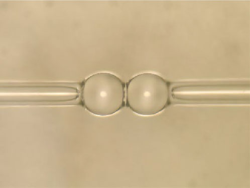
Figure 1. Microscopic image of dual-hollow-sphere-shaped optical microresonator.
Before testing its acoustic and magnetic field sensing performance, the optical quality factor is firstly measured with the experimental setup in Figure 2. The triangular wave generated by the function signal generator is sent to the frequency modulation terminal of the tunable laser (spectral range: 1,510 nm ∼ 1,630 nm) through the servo controller. This triangular wave is simultaneously sent to the oscilloscope as a trigger signal for transmission spectrum measurement. The output light from the laser is sent to the fiber taper (waist diameter about 1 µm, taper length about 50 mm) through a fiber attenuator and fiber controller. The fiber taper is evanescently over-coupled to the dual-hollow-sphere-shaped optical microresonator, and the transmission light is received by the detector and sent to the oscilloscope. The measured optical mode is shown in Figure 3, the corresponding quality factor is
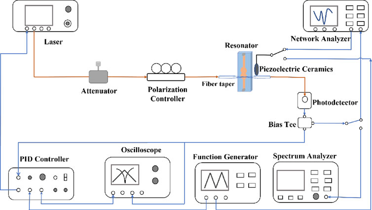
Figure 2. Experimental setup for acoustic and magnetic field sensing.
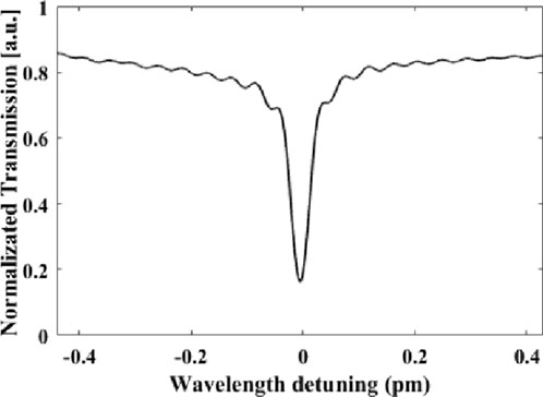
Figure 3. The optical mode chosen to perform acoustic and magnetic field sensing.
In the presence of an acoustic signal, the effective refractive index
When the laser wavelength is locked to the optical mode during measurement, the variation of wavelength will change light intensity. The intensity change can reflect the power strength of the acoustic signal [24].
The resonator itself cannot respond to the magnetic field, so additional magnetostrictive material (Terfenol-D) needs to be brought into the system [25]. The magnetostrictive material will stretch the resonator and thus change its transmission under a magnetic field. The strain induced by the magnetic field can be calculated by
in which
The magnetic field-induced wavelength change will also be reflected by the transmission property of the resonator.
Therefore, in theory, the resonator attached to Terfenol-D can respond to both the acoustic and magnetic field signal.
The acoustic and magnetic field sensing performance is characterized by the experimental setup shown in Figure 2. Then, the response to two signals at different frequencies is tested. The PID control box, function generator, and the Bias Tee that can separate the AC and DC signal are utilized to lock the laser wavelength to the resonance of the optical mode. The acoustic signal and the magnetic field signal are applied through the PZT and the coil via the function generator, respectively. The spectrum analyzer can be used to measure the noise power spectrum and the response at a certain frequency. The network analyzer can record the system response while the frequency-sweeping acoustic or magnetic field signal is on.
Firstly, the reference sinewave acoustic signal (20 V, 725.3 kHz), obtained by the PZT and the signal generator, is applied to the system and recorded by the spectrum analyzer. The signal-to-noise-ratio (SNR) of 27.5 dB for the reference acoustic signal is obtained under a certain resolution bandwidth (1.3 kHz), and the result is shown in Figure 4A. During the test, the PZT is moved away from the resonator when the function generator is still on, and the peak signal on the spectrum analyzer disappears, showing that the peak response is the actual acoustic response.
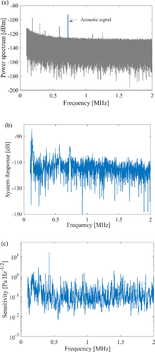
Figure 4. Acoustic field sensing results: (A) Power spectrum with a reference signal at 725.3 kHz; (B) System response at the frequency range of [0.1 MHz∼2 MHz]; (C) Acoustic field sensitivity at the frequency range of [0.1 MHz∼2 MHz].
Then, the minimum detectable acoustic field can be calculated by Equation 3:
where
The system response with a sweeping acoustic signal recorded by the network analyzer is shown in Figure 4B. It can be seen that the system has a stronger response within 100∼200 kHz.
The sensitivity of the acoustic field is then calculated with Equation 4:
where
Afterward, the magnetic field response is tested under the same procedure. A reference magnetic field signal around 546.5 kHz is applied to the resonator through the coil, and the power spectrum shown in Figure 5A with and without magnetic signal is acquired by the spectrum analyzer. The SNR of the magnetic field signal at 546.5 kHz is about −54.86 dB. The sensitivity is calculated by Equation 5:
In which,
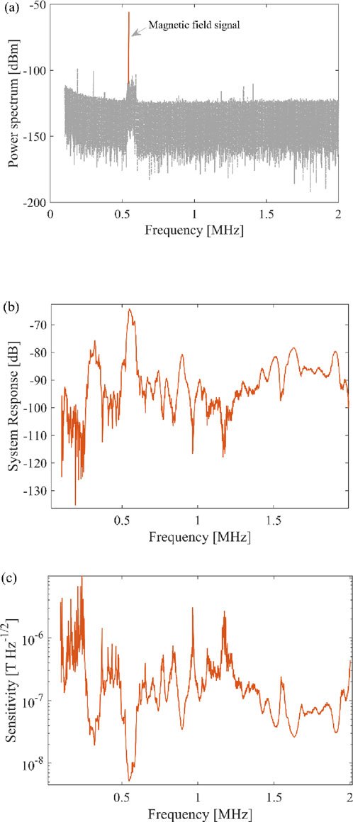
Figure 5. Magnetic field sensing results: (A) Power spectrum with a reference signal at 546.5 kHz; (B) System response at the frequency range of [0.1 MHz∼2 MHz]; (C) AC magnetic field sensitivity at the frequency range of [0.1 MHz∼2 MHz].
The system response is tested with the network analyzer and illustrated in Figure 5B. Based on noise spectrum, the system response and the minimum detectable magnetic field, the sensitivity within the frequency range of [0.1 MHz∼2 MHz] is obtained and shown in Figure 5C. The results show that the best sensitivity of 5.16 nT/√Hz locates at 546.5 kHz, and the relatively high sensitivities at the frequency ranges of [0.1 MHz ∼ 0.5 MHz], [1 MHz ∼ 1.5 MHz] and [1.5 MHz ∼ 2 MHz] are 12.0 nT/√Hz @ 377.9 kHz, 105.4.0 nT/√Hz @ 1.2786 MHz, 30.3 nT/√Hz @ 1.9853 MHz, respectively.
Furthermore, the system response is tested when both magnetic and acoustic signals are applied simultaneously. The results are shown in Figure 6. In Figure 6A, when a magnetic field signal of 896.8 kHz is firstly applied to the system (red dash line), then various frequencies of acoustic signals at 877.3 kHz, 887.3 kHz, 891.8 kHz, 895.8 kHz, 897.8 kHz, 901.8 kHz, 906.3 kHz, and 916.3 kHz are subsequently applied to the system (blue solid line). The strength and the frequency of the magnetic field signal barely altered and the frequency variation of acoustic signal has no significant impact on the detected magnetic field signal. The results in Figure 6B are performed in the reverse order. The acoustic signal at reference frequency 896.8 kHz is firstly applied to the system, and the magnetic field signal at different frequencies of 877.3kHz, 887.3 kHz, 891.8 kHz, 895.8 kHz, 897.8 kHz, 901.8 kHz, 906.3 kHz, and 916.3 kHz are then applied to the system. Similar behavior is observed that the frequency variation of the magnetic field signal almost has no impact on the strength and frequency of the acoustic signal. Therefore, it can be deduced that the acoustic and magnetic field signals at different frequencies have no impact on each other.
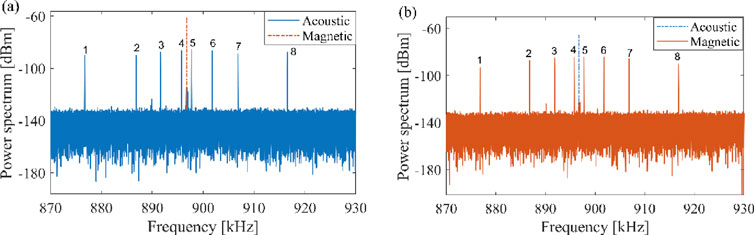
Figure 6. Power spectrum responses of the dual-hollow-sphere-shaped optical microresonator: (A) The 896.8 kHz magnetic field response to the acoustic signals at different frequencies. (B) The 896.8 kHz acoustic response to the magnetic field signals at different frequencies.
In practical applications, the commercial sound level meter or magnetoresistance sensor can be introduced to more accurately calibrate the acoustic field or magnetic field reference signal generated by the PZT and coil driven by the signal generator, so that the sensitivities can be more accurately determined. In addition, the repeatability of the sensing system can be improved by introducing the on-chip micro-resonator structure and its processing or packaging technology to ensure the uniformity of different sensing units during application [27–29]. Note that the frequency position of the best sensitivity of the magnetic field sensor is related to the mechanical mode of the resonator. It can be tuned by adjusting the frequency position of the mechanical mode which can be achieved by stress regulation [30], so that the detection needs of different magnetic field frequencies in practical applications can be met.
There are other ways to perform the acoustic and magnetic field sensing within one sensing system, such as the optoelectronic hybrid fiber laser sensor and cascaded fiber Bragg grating [21, 22], the results are compared in Table 1. For the optoelectronic hybrid fiber laser sensor, the resolutions of the acoustic pressure and AC magnetic field were respectively ∼ mPa and ∼μT [21]. Our sensor exhibits a similar acoustic resolution but a better AC magnetic field resolution at the nT range. Concurrently, it is important to note that the optoelectronic hybrid fiber laser sensor is limited in its detection capabilities, as it can only perceive the magnetic field component that is oriented along the y-axis. In contrast, our sensor stands out for its superior functionality, as it is designed to be sensitive to the overall amplitude of the magnetic field, considering all its vector components. This advanced feature allows our sensor to provide a more precise and comprehensive detection of the magnetic field’s presence and strength. Additionally, the cascaded fiber Bragg grating can detect both the acoustic and DC magnetic field signal with the corresponding sensitivities of 52.9 dB–300 kHz/47.3 dB to 1 MHz and 0.82 dB/mT [22]. However, as shown in Figure 4A, the acoustic SNR of our sensor at 725.3 kHz is around 27.5 dB with a driving voltage of 20 V, being more efficient than that of fiber Bragg grating which has an acoustic sensitivity of 47.3 dB to 1 MHz under a driving voltage of 400V. In the context of high-voltage power transmission, the choice between DC and AC technologies is contingent upon the length of the transmission line, which consequently results in either a DC or AC magnetic field being present. This implies that for practical applications, the ability to detect only DC magnetic fields is insufficient. Our sensor is capable of detecting both DC and AC magnetic fields, thereby extending their applicability to a broader spectrum of real-world scenarios. Furthermore, our sensor can realize acoustic and AC magnetic field sensing across a wider frequency range, which is particularly beneficial for applications where diverse frequency ranges are likely to be encountered.
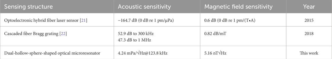
Table 1. Dual parameter sensing results comparison.
Adopting a CO2 laser to fabricate our resonator may allow for a resonator with thinner walls, which brings better sensitivity. Additionally, the coupling position of the fiber taper to the resonator is a critical parameter that affects sensitivity. Prior studies have indicated that the strain is maximized when the fiber taper is positioned at the junction of the two hollow spheres, where the stress concentration is highest. This positioning strategy can be further optimized to achieve even higher sensitivity.
On-chip resonators with high quality factors benefit for practical implementation [27, 28], the system will be more compact. The packaging process for the proposed fiber taper and microresonator can follow the steps outlined for Saddle-Shape optical microresonators [26], thereby ensuring the protection of the sensitive components and enhancing the system’s overall stability.
An acoustic and AC magnetic field dual parameter sensor is realized with a dual-hollow-sphere-shaped optical microresonator. The acoustic and magnetic field sensitivity are 4.24mPa/√Hz and 5.16 nT/√Hz, respectively. Additional experimental results show that the two parameters can be simultaneously detected when they have separate frequencies. Further enhancements in sensitivity are achievable through structural optimization, allowing for even more precise measurements. Additionally, the stability of the sensor can be significantly improved by refining the packing procedure, ensuring consistent and reliable performance in various environments. This proposed optical sensing scheme introduces a novel system with potential applications in non-destructive high-voltage transmission lines monitoring. This not only broadens the scope of sensing technology in electrical systems, but also opens new possibilities for complex environmental monitoring.
The raw data supporting the conclusions of this article will be made available by the authors, without undue reservation.
CF: Formal Analysis, Investigation, Writing–original draft, Writing–review and editing. CY: Conceptualization, Data curation, Formal Analysis, Investigation, Methodology, Project administration, Writing–original draft, Writing–review and editing. YH: Writing–original draft. JC: Writing–review and editing. PH: Writing–review and editing. HL: Writing–review and editing. YG: Writing–review and editing.
The author(s) declare that financial support was received for the research, authorship, and/or publication of this article. This work was supported by Zhejiang Provincial Natural Science Foundation of China (Grant No. Y24F050044), the “Pioneer” and “Leading Goose” R&D Program of Zhejiang Province (2022C01053, 2024C01003), National key research and development program (Grants No. 2022YFF1400100), and the National Natural Science Foundation of China (Grant No. 12404542).
Authors CF, JC, and PH were employed by Ultra High Voltage Company of Stats Grid Shaanxi Electric Power Co., Ltd.
The remaining authors declare that the research was conducted in the absence of any commercial or financial relationships that could be construed as a potential conflict of interest.
The author(s) declare that no Generative AI was used in the creation of this manuscript.
All claims expressed in this article are solely those of the authors and do not necessarily represent those of their affiliated organizations, or those of the publisher, the editors and the reviewers. Any product that may be evaluated in this article, or claim that may be made by its manufacturer, is not guaranteed or endorsed by the publisher.
1. Kyu Hyun K, Wei L, Cheng Z, Tian C, Guo LJ, Wang X, et al. Air-coupled ultrasound detection using capillary-based optical ring resonators. Scientific Rep (2017) 7(1):109. doi:10.1038/s41598-017-00134-7
2. Miao Y, Yangxi Z, Ouyang X, Ping Zhang A, Tam HY, Wai PKA. Ultracompact optical fiber acoustic sensors based on a fiber-top spirally-suspended optomechanical microresonator. Opt Lett (2020) 45(13):3516–9. doi:10.1364/ol.393900
3. Zhao CY, Li PY, Zhang CM. Numerical analysis of effective refractive index ultrasonic sensor based on Cantilever arm structure slot-based dual-micro-ring resonator. Int J Mod Phys B (2021) 35(4):2150058. doi:10.1142/s0217979221500582
4. Hao Y, Xuening C, Zhigan H, Gao Y, Lei Y, Wang M, et al. Micropascal-sensitivity ultrasound sensors based on optical microcavities. Photon Res (2023) 11(7):1139–47. doi:10.1364/prj.486849
5. Xiaoping L, Rende M, Yunjie X. Magnetic field sensor exploiting light polarization modulation of microfiber with magnetic fluid. J Lightwave Tech (2018) 36(9):1620–5. doi:10.1109/JLT.2017.2785300
6. Lifeng B, Xinyong D, Shuqin Z, Changyu S, Ping S. Magnetic field sensor based on magnetic fluid-infiltrated phase-shifted fiber Bragg grating. IEEE Sensors J (2018) 18(10):4008–12. doi:10.1109/JSEN.2018.2820741
7. Alcheikh N, Younis MI. Resonator-Based bidirectional lorentz force magnetic sensor. IEEE Electron Device Lett (2021) 42(3):406–9. doi:10.1109/led.2021.3055896
8. Shuai S, Anming G, Yuting W, Tao W Wide bandwidth lorentz-force magnetometer based on lateral overtone bulk acoustic resonator [C]. In: IEEE 34th international conference on micro electro mechanical systems (2021). 9375335.
9. Yansong L, Weiwei Z, Minhao W, Liu J. Optical current sensing mechanism under a non-uniform magnetic field. Appl Opt (2019) 58(20):5472–8. doi:10.1364/ao.58.005472
10. Alex D, Juan David L, Cesar Cosenza C, Regina Celia DSA, Marcelo MW. A compact FBG-based toroidal magnetostrictive current sensor with reduced mass of terfenol-D. IEEE Photon Tech Lett (2019) 31(17):1461–4. doi:10.1109/LPT.2019.2932112
11. Ying G, Yundong Z, Huaiyin S, Zhu F, Yi G, Wang J. Magnetic-field tuning whispering gallery mode based on hollow microbubble resonator with Terfenol-D-fixed. Appl Opt (2019) 58(32):8889–93. doi:10.1364/ao.58.008889
12. Yutang D, Minghong Y, Gang X, Yuan Y. Magnetic field sensor based on fiber Bragg grating with a spiral microgroove ablated by femtosecond laser. Opt Express (2013) 21 (14):17386–91. doi:10.1364/oe.21.017386
13. Hai L, Hongwei L, Qing W, Meng W, Yi D, Chenghao Z, et al. Temperature-compensated Magnetic Field sensor based on Surface Plasmon Resonance and directional Resonance coupling in a D-shaped photonic crystal fiber. Optik (2018) 158:1402–9. doi:10.1016/j.ijleo.2018.01.033
14. Fengyu H, Xiaobei Z, Zijie W, Lei Y, Wen S, Yong Y, et al. Magnetic fluid infiltrated microbottle resonator sensor with axial confined mode. IEEE Photon J (2020) 12(5):6802709. doi:10.1109/JPHOT.2020.3024110
15. Liang Z, Huiqun Y, Xin L. Synchronous vibration parameters identification of variable rotating speed blades based on new improved two-parameter method without OPR sensor. Shock and Vibration (2021) 2021:5860353. doi:10.1155/2021/5860353
16. Yacoby E, Meshorer Y, London Y. Magnetic sensor based on a whispering gallery mode double-tailed silica microsphere. Opt Laser Tech (2022) 151:108019. doi:10.1016/j.optlastec.2022.108019
17. Ning L, Changping X, Yinping M, Bai Y, Zheng Y. Hollow-core anti-resonant fiber magnetic field sensor based on negative curvature Semi-Tubular. Opt Fiber Tech (2024) 82:103593. doi:10.1016/j.yofte.2023.103593
18. Gotardo F, Carey BJ, Greenall H, Harris GI, Romero E, Bulla D, et al. Waveguide-integrated chip-scale optomechanical magnetometer. Opt Express (2023) 31(23):37663–72. doi:10.1364/oe.501960
19. Shangpeng Q, Junyang L, Yang Y, Li M, Junbo Y, Zhang Z, et al. Magnetic field and temperature two-parameter sensor based on optical microfiber coupler interference (OMCI) wrapped with magnetic fluid and PDMS. Opt Express (2021) 29(18):29492–504. doi:10.1364/oe.435864
20. Yukun S, Li L, Jiawei G, Hu C, Deng L, Jiang C, et al. Simultaneous measurement three parameters of temperature, strain, and curvature by thin-core fiber based-Mach-Zehnder interferometer. Opt Fiber Tech (2023) 80:103377. doi:10.1016/j.yofte.2023.103377
21. Zhaogang W, Wentao Z, Wenzhu H, Feng S, Li F. Optoelectronic hybrid fiber laser sensor for simultaneous acoustic and magnetic measurement. Opt Express (2015) 23(19):24383–9. doi:10.1364/oe.23.024383
22. Xiaohong B, Manli H, Tingting G, Qiangzhou R. Simultaneous acoustic and magnetic measurement using cascaded fibre Bragg grating. Opt Fiber Tech (2018) 45:376–82. doi:10.1016/j.yofte.2018.07.017
23. Jingshun P, Bin Z, Zhengyong L, Zhao J, Feng Y, Wan L, et al. Microbubble resonators combined with a digital optical frequency comb for high-precision air-coupled ultrasound detectors. Photon Res (2020) 8(3):303–10. doi:10.1364/prj.376640
24. Presas A, Yongyao L, Zhengwei W, Valentin D, Egusquiza M. A review of PZT patches applications in submerged systems. Sensors (2018) 18(7):2251. doi:10.3390/s18072251
25. Lee EW. Magnetostriction and magnetomechanical effects. Rep Prog Phys (1955) 18(1):184–229. doi:10.1088/0034-4885/18/1/305
26. Yacoby E, London Y. Saddle-shape whispering gallery mode microresonators. J Lightwave Tech (2023) 41(10):3139–44. doi:10.1109/jlt.2023.3237696
27. Kaikai L, Naijun J, Haotian C, Chauhan N, Puckett MW, Nelson KD, et al. Ultralow 0.034 dB/m loss wafer-scale integrated photonics realizing 720 million Q and 380 μW threshold Brillouin lasing. Opt Lett (2022) 47(7):1855–8. doi:10.1364/ol.454392
28. Giuseppe B, Francesco DO, Donato C, Armenise MN, Ciminelli C. Comprehensive mathematical modelling of ultra-high Q grating-assisted ring resonators. J Opt (2020) 22:035802. doi:10.1088/2040-8986/ab71eb
29. Chenchen Z, Alexander C, Eugene F, Liu Z, Tadigadapa S. On-chip glass microspherical shell whispering gallery mode resonators. Scientific Rep (2017) 7:14965. doi:10.1038/s41598-017-14049-w
Keywords: electromagnetic detection, acoustic sensing, multi-parameter, optical microresonator, microsphere
Citation: Feng C, Yu C, Hu Y, Chang J, Hou P, Li H and Guo Y (2025) Dual hollow sphere optical resonator for simultaneous detection of acoustic and magnetic fields. Front. Phys. 13:1539959. doi: 10.3389/fphy.2025.1539959
Received: 05 December 2024; Accepted: 06 January 2025;
Published: 06 February 2025.
Edited by:
Zhaohong Liu, Hebei University of Technology, ChinaReviewed by:
Yongfeng Wu, Nanjing University of Information Science and Technology, ChinaCopyright © 2025 Feng, Yu, Hu, Chang, Hou, Li and Guo. This is an open-access article distributed under the terms of the Creative Commons Attribution License (CC BY). The use, distribution or reproduction in other forums is permitted, provided the original author(s) and the copyright owner(s) are credited and that the original publication in this journal is cited, in accordance with accepted academic practice. No use, distribution or reproduction is permitted which does not comply with these terms.
*Correspondence: Changqiu Yu, Y3F5dUBoZHUuZWR1LmNu
Disclaimer: All claims expressed in this article are solely those of the authors and do not necessarily represent those of their affiliated organizations, or those of the publisher, the editors and the reviewers. Any product that may be evaluated in this article or claim that may be made by its manufacturer is not guaranteed or endorsed by the publisher.
Research integrity at Frontiers
Learn more about the work of our research integrity team to safeguard the quality of each article we publish.