
94% of researchers rate our articles as excellent or good
Learn more about the work of our research integrity team to safeguard the quality of each article we publish.
Find out more
ORIGINAL RESEARCH article
Front. Phys., 26 March 2025
Sec. Optics and Photonics
Volume 13 - 2025 | https://doi.org/10.3389/fphy.2025.1539099
This article is part of the Research TopicAdvanced High Power Solid-State Laser Technology, Volume IIView all articles
 Samuel P. Bingham1*
 Daniel Matyas2
 Mark Mihalik3
 Thomas W. Hawkins4
 Monica T. Kalichevsky-Dong1
 John Ballato4
 Liang Dong1
There is a lack of general study of the maximum pulse energy from fiber amplifiers with short durations (up to few hundreds of nanoseconds) that are limited by amplified spontaneous emission, which slows inversion growth and degrades pulse contrast. We have conducted a systematic study of a monolithic master oscillator power amplifier (MOPA) by varying pulse duration, repetition rate and fiber length using an in-house fabricated ytterbium-doped double-clad 50/250 fiber that demonstrated ∼20ns pulses at ∼1.5 mJ, 100 kHz repetition rate and ∼200 W average power with an M2 = ∼1.1. The highest pulse energy obtained is ∼1.7 mJ within the main pulse. This pulsed fiber laser was limited only by fiber fuse, which happens roughly between 1 and 2 mJ pulse energy regardless of pulse durations, fiber lengths and repetition rates tested. The model reported herein in this study is consistent with most experimental data in the literature and our own experimental data.
Pulsed fiber lasers have a wide range of scientific and industrial applications in material processing and remote sensing [1]. Output pulse energy is an important parameter for pulsed lasers. Currently, the literature lacks a general study of the limit of output pulse energies that can be extracted from a given fiber master oscillator power amplifiers (MOPA) when different seed pulse energies and fiber designs are considered. The only exception to which is a study on the extractable energy in Q-switched ytterbium-doped fiber lasers dependent on pump power [2].
Previously, we have conducted a theoretical study of output pulse energy from a pulsed ytterbium-doped diffraction-limited fiber MOPA using a fiber amplifier model considering both local nonlinear effects (Raman and Kerr) and linear effects (loss, gain, and group velocity dispersion) along the fiber amplifier [3]. Local gain depletion (time-dependent gain due to inversion depletion) and gain dispersion (wavelength-dependent gain) are also considered in the model. Pumping effects were not considered during the pulse transit through the fiber and the study was only applicable to pulses in the short pulse regime where the pumping effect can be ignored. Critically, it was assumed that the maximum inversion was limited by amplified spontaneous emission (ASE) where any further inversion increase will degrade pulse contrast and will be clamped by the significant amount of ASE generated in the fiber core. Our model therefore represents the maximum output pulse energy from a short-pulse fiber MOPA.
Our model uses a new form of the nonlinear equation developed in the form an ordinary differential equation (ODE) [4]. The key benefit of this form of the nonlinear equation is that it can be directly integrated using a commercial ODE solver, leading to superior accuracy and efficiency. This model has played a major role in the development of supercontinuum generation in optical fibers. In our model, such direct-ODE-integrable nonlinear equation is revised to include both gain saturation and gain dispersion for fiber lasers. In addition, separate rate equations are incorporated to allow local pump absorption, inversions, and ASE in both directions to be considered. This model is developed for ytterbium fiber lasers, but it can be easily adapted for other fiber lasers.
In this work, we first extended and updated the comparison of this model with nanosecond diffraction-limited MOPA results reported in the literature and confirmed the general agreements between the modelled pulse energy and measured pulse energy. We then proceeded to conduct an experimental study of a two-stage diffraction-limited monolithic fiber MOPA consisting of a seed diode directly modulated to generate pulses spanning a few nanoseconds to hundreds of nanoseconds using an in-house fabricated ytterbium-doped double-clad power amplifier fiber with a 50 μm core diameter, 250 μm cladding diameter, and a 0.028 NA (see [5] for more details on this fiber). Our experimental results using an ytterbium-doped 25/250 fiber in the pre-amplifier and the ytterbium-doped 50/250 fiber in the power amplifier are in general agreement with our model. The pulse energies from this MOPA are, however, found to be limited to ∼1.7 mJ by fiber fuse regardless of pulse duration, fiber length, and repetition rate tested, short of the expected theoretical limit of ∼3.8 mJ. These results represent a first systematic study on pulse energy limit from a diffraction-limited fiber MOPA and some of the highest combinations of pulse energies and average powers from a monolithic fiber MOPA that are critical for material processing in many industrial applications.
Energy extraction from a fiber MOPA is first dependent on the level of inversion that can be achieved before pulse arrival. This determines the extractable energy, i.e., the part of the total stored energy that can be extracted if the inversion is reduced to the level of net-zero gain everywhere along the fiber [2]. The maximum inversion is, however, limited by the ASE that can develop between pulses as inversion grows. This ASE growth eventually clamps inversion and leads to excessive power between pulses, severely degrading pulse contrast. The threshold is determined in our model by increasing the pump powers in an ytterbium-doped fiber amplifier without any seed until the total ASE power exiting both ends of the fiber reaches 0.1 W. No spurious reflections were assumed anywhere along and from the ends of the active fiber.
In this case, the ASE is directly generated internally in the fiber from quantum noise in a single pass through the fiber. The choice of 0.1 W is arbitrary. The ASE power in this high gain regime in typical fibers, however, increases extremely fast beyond this point. Any further inversion increase is severely limited beyond this point in a practical fiber amplifier. This threshold condition provides a reasonable estimate of the maximum inversion. In practice, there are spurious reflections in a fiber amplifier as well as some seed power between pulses due to imperfect pulse contrast. Accordingly, the ASE can be significantly enhanced by the much-higher-than-quantum-noise seeding and multiple passages through the fiber amplifier due to these spurious reflections.
Energy extraction is also dependent on the seed energy and how the pulse is amplified along the fiber. The extraction is weak at the front end of the fiber due to the weak signal and increases towards the output. In our analysis, the total extracted energy is always below 50% of the extractable energy even when seeded significantly above the saturation energy in a fiber amplifier [3]. This is primarily due to the lower pulse energy at the front-end of the amplifier which leads to poor overall energy extraction efficiency. Higher pulse energy can be extracted from a Q-switched fiber laser due to the much more intense pulse throughout the fiber [5].
An example fiber is modelled using a 1 m-long 50 μm core step-index fiber with a 0.06 NA and a cladding diameter of 250 μm [3]. The ytterbium concentration is 8.52 × 1025 ions/m3, corresponding to 1.25wt% of Yb. The pump absorption in the cladding and small-signal gain in the core at full inversion are shown in Figure 1. The peak pump absorption is 20 dB/m at ∼976 nm. The output pulse energy and total ASE (calculated by integrating ASE as a function of wavelengths and in both directions) are shown in Figure 2a versus the launched pump power at 915 nm, seeded with a 1ns pulse at a seed energy, Ein, equaling a saturation energy, Esat of 604.9 μJ at 1035 nm. The vertical line in Figure 2a represents the launched pump power at 915 nm where the total ASE power is 0.1W, i.e., the threshold used in this work, and the output pulse energies show a clear sign of saturation beyond this point. Expectedly, the total ASE power becomes significant at higher pump powers and clearly presents a limit where ASE can significantly degrade the temporal contrast of optical pulses.
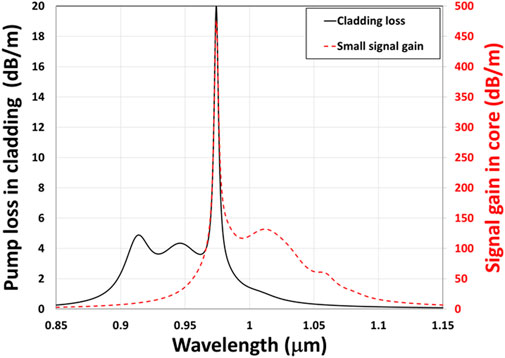
Figure 1. Pump absorption in the cladding and small-signal gain at 100% inversion in the core for the 50/250 fiber used in the model.
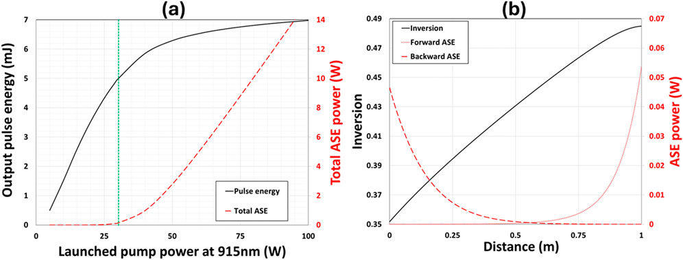
Figure 2. (a) Output pulse energy and total ASE power versus 915 nm pump power (green vertical line indicates 0.1 W of total ASE at a pump power of 28.93 W) and (b) inversion and ASE for the counter-pumped pump of 28.93 W (1 m of the 50/250 fiber, Ein = Esat = 604.9 μJ at 1,035 nm, counter-pumping at 915 nm).
In this case, the 0.1 W total ASE power occurs at a pump power of about 28.9 W at 915 nm with an output pulse energy of 4.85 mJ. The extractable energy is 10.04 mJ at this pump power, slightly more than twice the output energy. The inversion and ASE power in both directions in the fiber are shown in Figure 2B at the launched pump power of 28.9 W. The single-pass gain in the core at this inversion is over 40 dB at the ASE peak (see Figure 1). The ASE is entirely seeded inside the fiber and generated over a single pass through the fiber. For a practical fiber amplifier of a few meters, the buildup time of the ASE in this case is equivalent to the transit time through the fiber amplifier of just a few nanoseconds, much shorter than the 2 μs between pulses at 500 kHz repetition rate, the highest in a high-power pulsed fiber MOPA to date [6]. There are always spurious reflections in a fiber system. In this case, the ASE could pass the fiber amplifier several hundreds of times within 2 μs, worsening the ASE in the system far beyond the single-pass scenario considered in our model. The maximum output pulse energy from a short-pulse fiber MOPA predicted here should provide a reasonable estimate for all practical repetition rates in a high-power fiber MOPA system.
The pumping effect is ignored during the pulse transit through the model fiber. In a practical pulsed fiber MOPA, the fiber is pumped for a finite time between pulses to recover to its previous maximum inversion before the arrival of the next pulse. In a MOPA designed for high pulse energy output, pump power is scaled such that the inversion is sufficiently recovered before the arrival of the subsequent pulse.
For a given length of fiber, our model first calculates the total ASE exiting the fiber ends for a given pump power in the absence of any seed by simulating the local inversion and propagation of ASE seeded at one photon per mode in each direction. The pump power is gradually increased until the total ASE power reaches 0.1 W at two fiber ends. The pump power is then fixed, the model then simulates the propagation of a single pulse through the fiber considering local gain depletion, gain dispersion, group velocity dispersion (GVD), Kerr nonlinearity, and stimulated Raman scattering, assuming there is negligible pumping during the short pulse transit [3]. Stimulated Brillouin scattering is not considered since it is not generally an issue in pulsed fiber lasers. The output pulse is generally steeper at the leading edge and narrower due to gain saturation. The pulse energy at the output is obtained by integrating power over the entire pulse in the time domain.
The 1 m-long double-clad ytterbium-doped fiber (50/250 0.06NA) used in the model has a small-signal pump absorption of 20 dB/m at 976 nm with ytterbium concentration at 8.52 × 1025 ions/m3 [3]. Given the ASE limit, output energy changes little for counter-pumping wavelengths at 915 nm or 976 nm in this fiber. The actual pump absorptions are almost identical in these two cases due to the high inversions at the ASE limit. Counter-pumping at 915 nm is then used as a default in our model. Variations of output pulse energy versus fiber length and ytterbium concentration are also observed to be small at the ASE limit, less than 7% from 0.5 to 2.5 m while fixing the ytterbium concentration at 1.49 × 1026 ions/m3 or ytterbium concentration from 4 × 1025 to 2.4 × 1026 ions/m3 while fixing the fiber length at 1 m. The pulse energy peaks at a seed wavelength of ∼1030 nm but less dependent on wavelength when the seed pulse energy is near the saturation energy. More details are provided in [3]. The output pulse energy was simulated for seed pulse energy of 1%, 10%, and 100% of the saturation energy versus the core diameter at 1035 nm where the saturation energy is ∼605 μJ (see Figure 3). The small-signal pump absorption is kept constant at 8.74 dB/m at 915 nm by adjusting fiber length when the core diameter is changed.
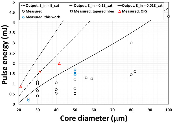
Figure 3. Simulated output pulse energy at 1,035 nm at Ein/Esat of 1%, 10%, and 100% along with measured data from diffraction-limited nanosecond fiber MOPA in the literature and experimental data from this study (see Table 1 for details of the literature). The small-signal pump absorption is kept constant at 8.74 dB/m at 915 nm by adjusting fiber length when the core diameter is changed. The fiber is counter-pumped at 915 nm. Maximum core diameters are used for the tapered fibers in [21, 22] (see Table 1).
The experimental data from the literature displayed in Figure 3 are for diffraction-limited nanosecond MOPAs (see Table 1 for details and References). The seed energies are not always available in the literature. The maximum pulse energy from a fiber MOPA should be below the simulated curves for the appropriated seed energies. Most of the experimental data are in general agreement with the simulated curves considering all the uncertainties. The two data point at 30 μm core just above the simulated curve for the seed energy at 1% of the saturation energy with output pulse energies of 1.05 mJ [9] and 1.1 mJ [11] had seed energies at ∼1.5% and ∼2.1% of the saturation energy, close to what are expected from the model. Our own data at 50 μm core with an output energy of ∼2 mJ had a seed energy of ∼28% of the saturation energy, well below the theoretical prediction of ∼3.8 mJ (more discussion on this later). Most of the experiments in Figure 3 were seeded below 1 percent of the saturation energy.
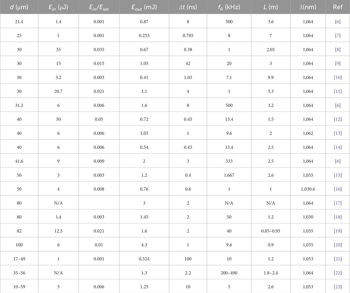
Table 1. A summary of diffraction-limited nanosecond pulsed fiber MOPA in the literature used in Figure 3 (d: core diameter, Ein: seed energy, Eout: output energy, Δt: pulse width, fR: repetition rate, L: fiber length, λ: seed wavelength).
The major exception to our model in Figure 3 is the data from OFS [6]. The output pulse energies of 1.4mJ, 1.6mJ and 2 mJ of the OFS data were produced with seed energies of ∼0.1%, ∼0.6%, and ∼0.9% of the saturation energy respectively. The temporal pulse measurement in the OFS work however used an AC-coupled detector (Thorlabs FPD310-FC-NIR) [6], which cuts off all frequencies below 1 MHz. ASE, mostly at low frequencies, cannot be observed in such measurements. The measured spectra did not show significant ASE but cannot exclude much degraded pulse contrast at the output due to amplification of the seed powers present between the main pulses in the original seed [6].
The validity of our model was further evaluated using two-stage monolithic MOPA seeded by a directly modulated diode from AeroDiode providing pulses from a few nanoseconds to hundreds of nanoseconds at ∼1030 nm (see Figure 4). The repetition rate can be adjusted over a wide range up to few MHz. For the repetition rate at 100 kHz, the pulse energy, power and spectrum from the diode measured at the output of the pump combiner for the pre-amplifier are shown in Figure 5 for various set seed pulse durations. The pulse shapes are given in Figure 6 for two timescales showing there is still a pre-pulse power of few percent of the peak power present before the pulse leading edge.
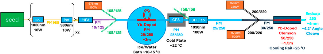
Figure 4. The two-stage MOPA used in the experiments (iso: isolator, MFA, mode field adaptor, CPS: cladding power stripper, BPF: bandpass filter, PM: polarization maintaining fiber).
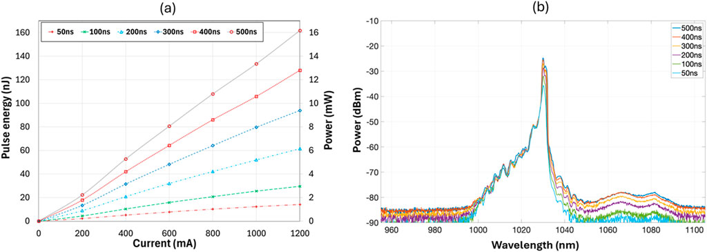
Figure 5. (a) Pulse energy and power and (b) spectrum from the seed diode measured at the output of the pump combiner for the pre-amplifier for various set pulse durations shown in the Figures.
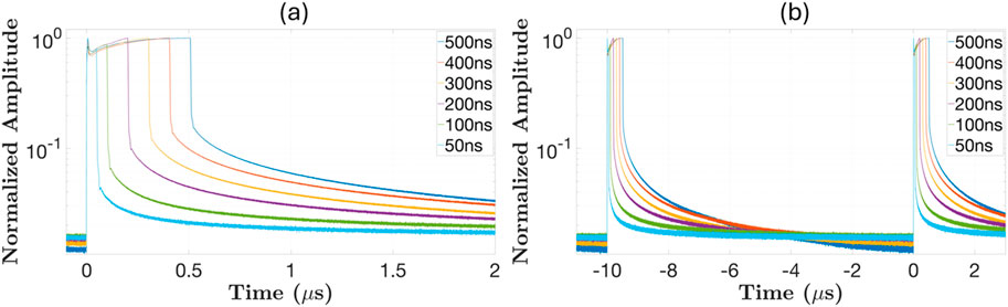
Figure 6. Pulse shape in logarithmic vertical scale with (a) close-in and (b) zoom-out time scale from the seed diode measured at the output of the pump combiner for the pre-amplifier for various set pulse durations shown in the Figures.
The first stage consists of ∼3 m PM ytterbium-doped 25/250 Coherent fiber (PLMA-YDF-VIII), cooled in a water/ice bath. The length was optimized for the maximum pulse energy. A 6 nm bandpass filter was built into the isolator (DK Photonics) after the pre-amplifier for ASE suppression. Output pulse energy and power from the pre-amplifier measured at the output of the pump combiner for the power amplifier for various set seed pulse durations are shown in Figure 7. The pump power was increased until there was sign of slowdown in the output power increase. Larger pulse energies can be obtained at longer pulse durations, but the increase is small above set seed pulse durations of 200 ns Pulse shape and spectrum at various powers for set seed pulse durations of 100, 200 and 300ns are given respectively in Figures 8–10. There is a clear sign of pulse narrowing at higher powers as result of gain depletion. Pulse width reduced to ∼65ns FWHM at 150 μJ for the 200ns seed pulse, a strong indication of nearing extraction limit. At high pulse energies, the pre-pulse power reduced to ∼0.1% of the peak power (see Figures 8–10). This is due to a combination of spectral filtering and gain depletion by the high intensity part of the pulse, resulting in improved pulse contrast. There is also sign of nonlinear spectral broadening at high pulse energies. Seeded at ∼60 nJ (0.04% of the saturation energy, 200 ns, 100 kHz repetition rate), a maximum of ∼200 μJ could be obtained from the 25/250 fiber in the pre-amplifier with a gain of ∼35 dB. The polarization extinction ratio (PER) was measured to be ∼20 dB at the output of the pump combiner for the power amplifier.
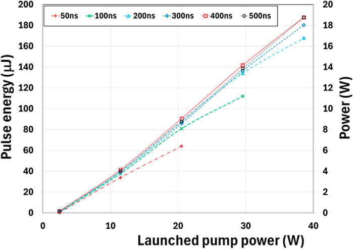
Figure 7. Power from the pre-amplifier measured at the output of the pump combiner for the power amplifier for various set pulse durations.
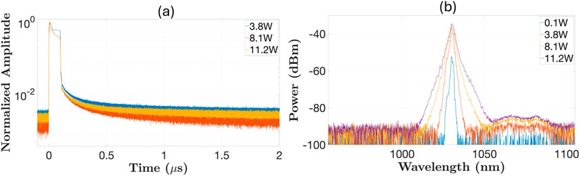
Figure 8. (a) Pulse shape and (b) spectrum at various powers from the pre-amplifier measured at the output of the pump combiner for the power amplifier for seed duration set at 100 ns.
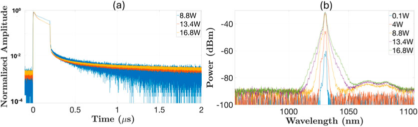
Figure 9. (a) Pulse shape and (b) spectrum at various powers from the pre-amplifier measured at the output of the pump combiner for the power amplifier for seed duration set at 200 ns.
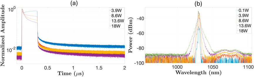
Figure 10. (a) Pulse shape and (b) spectrum at various powers from the pre-amplifier measured at the output of the pump combiner for the power amplifier for seed duration set at 300 ns.
The pump combiner of the power amplifier consisted of a 25/250 input fiber and 30/250 output fiber, which was then spliced to the in-house fabricated ytterbium-doped 50/250 fiber. This is the same fiber used in [5] with a 0.028 NA (see cross section image in Figure 11 and more details in [4]). The core is co-doped with Al and P, see [24] for more details. The pump absorption was measured to be ∼4.9 dB/m at 915 nm and was estimated to be ∼20 dB/m at 976 nm. The ytterbium-doped 50/250 fiber was typically 1.2–1.6 m long (see Table 2) and kept straight in a cooled V-groove due to the extremely low NA. We measured the MOPA performance 8 times, varying pulse duration, fiber length and repetition rate. Each time the power from the MOPA was limited by fiber fuse at the power amplifier, which happened between 1 and 2 mJ pulse energy regardless of pulse duration, fiber length, and repetition rate tested. Typically, a flame at the fiber would start a short distance away from the output end and burn for up to a few tens of centimeters. Unlike fiber fuse at lower powers [25], entire sections of fiber of up to few tens of centimeters were completely obliterated in our case. The detail of the runs is summarized in Table 2.
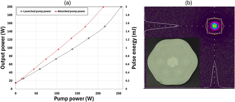
Figure 11. (a) Average power and pulse energy versus launched pump power and (b) mode image at the output of the power amplifier for the sixth run at the maximum power (200ns set seed duration, 1.21 m, 200 W average power). Fiber cross section image is shown in the inset.
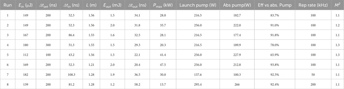
Table 2. Summary of MOPA performance (Ein: input energy, Eout: output energy, Δtset: set pulse duration, Δtin: input pulse width, Δtout: output pulse width, L: fiber length, Pmax: peak power, launch: launched, abs: absorbed, eff: efficiency, rep: repetition).
If seeded at 20% and 30% of the saturation energy (121 μJ and 181.5 μJ, respectively, with the saturation energy of 605 μJ at 1,035 nm), 3.62 mJ and 3.85 mJ of maximum output energy would be expected, respectively, from the 50/250 fiber according to our model. In run 6, 2 mJ pulse energy (∼1.5 mJ in the main pulse, see Table 3) and ∼200 W average power with M2 = 1.1 to 1.2 was achieved at the output before fiber fuse. The pulse was further narrowed to ∼20.4 ns FWHM in the sixth run (see Table 2).
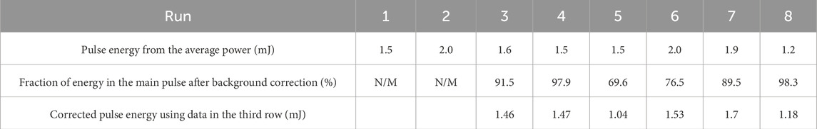
Table 3. Calculation of pulse energies in the main pulse (N/M: not measured).
Output power and pulse energy versus launched pump power is given in Figure 11a for the sixth run. The increasing slope towards higher pump power is due to the pump wavelength moving towards the Yb3+ absorption peak at higher pump powers. Optical efficiency was ∼94% relative to the absorbed pump powers. The mode at the output at the maximum power is shown in Figure 11b, showing excellent mode quality from the 50 μm core with a 0.028 NA [26]. Pulse shape and spectrum at various powers are shown in Figure 12 at the MOPA output for the sixth run. Some residual pump at∼976 nm can be seen in the spectrum as well as a changing of pump wavelength with increasing pump powers.
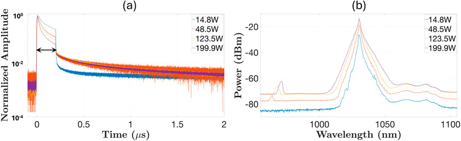
Figure 12. Pulse shape (a) and spectrum (b) at the output of the power amplifier for the sixth run.
Measured M2 (averaged over two axes) versus average output power is given in Figure 13 for the eighth run at 200 kHz repetition rate. This is typical of all runs. The initially large M2 is much reduced at higher powers due the preferential amplification of the fundamental mode in the ytterbium-doped 50/250 fiber. The fiber has a V value of ∼4.27 at 1,030 nm, supporting only four modes (LP01, LP11, LP21, and LP02) with the fundamental mode having a much better overlap with the gain. As pump power is increased, the power in the fundamental increases much faster than that in higher-order modes. Similar behavior has been observed before [27]. The transverse mode instability (TMI) threshold was not reached in this case. We have measured TMI threshold at various CW seed powers, see Figure 14, by measuring M2 at increasing pump powers and observing the increase of M2 above ∼10% from the base line. The TMI threshold at the average power of our pulsed seed, i.e., ∼28W, is expected to be ∼270 W for CW seed.
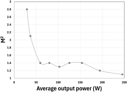
Figure 13. Measured M2 (averaged over two axes) versus average output power for the eighth run at 200 kHz repetition rate.
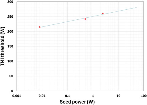
Figure 14. Measured TMI threshold versus 1030 nm CW seed powers for the Ytterbium-doped 50/250 fiber.
Pulse energy in Table 2 is calculated from the measured average output power and pulse repetition rate. This is only accurate if the ASE is negligible. Quantifying ASE from the optical spectrum is impossible considering optical filters are often used to suppress ASE in the pre-amplifiers. This creates a seed for the power amplifier carrying only ASE at wavelengths very close to the peak wavelength of the pulses. The ASE at the output of the power amplifier will be dominated at these ASE wavelengths in this case, i.e., very close to the peak wavelength of the pulses. In addition, optical pulses generated by directly modulating diodes often have limited contrast, i.e., there is unwanted optical power between main pulses at wavelengths very close to the peak wavelength of the pulses. This unwanted optical power can also seed ASE between pulses in the power amplifier, producing ASE at wavelengths very close to the pulse peak wavelength.
There are several other techniques for measuring pulse energy, but they are all limited in some ways. Pyro-electric energy meter can theoretically measure pulse energy, but they are limited to low pulse repetition rates far below the >50 kHz repetition rates used in this study. In addition, ASE often varies with time, making isolating it completely from the main pulses almost impossible. Acousto-Optic Modulator (AOM) can be used to suppress the main pulses so that the remaining power between the main pulses can be measured. This may be possible for blocking out a wide window around the pulses in [28] but is hard to do for high-power nanosecond pulses with millimeter beam waist due to the slow AOM turn on/off time (>100ns for an optical beam with a millimeter beam waist, fundamentally limited by the transit time of acoustic wave across the optical beam). Our beam size after the fiber is ∼3 mm. Faster AOM turn on/off time is only possible with much attenuated beam, allowing significantly smaller beam on the AOM. Optical power can be integrated over time using a specially designed circuit with a capacitor [29]. In this case, the main pulse will generate a fast raise in the capacitor voltage within the main pulse duration while ASE will show up as a slow rise between the main pulses. With the exception of the AOM approach, all the approaches are limited by detector dynamic range.
Time domain measurement techniques using fast detectors such as the integrating method in [28] can isolate main pulse from ASE in time domain and is more accurate assuming bandwidth, sensitivity and dynamic range are not limiting. In case where pulse energy is limited by strong ASE, the ASE in time domain is expected to follow the inversion which is at a maximum just before pulse arrival, at a minimum just after the passage of a pulse due to energy extraction by the pulse, and slowly increasing towards the next maximum due to the effect of pumping between pulses (see [28, 29]).
We used a 5 GHz detector (Thorlabs DET08CFC) and a 10-bit 50 GHz oscilloscope (Keysight UXR0504A, 256GSa/s) for our pulse measurement in the time domain. Once the optical power was reduced so that the detector was not saturated, the DC detection noise floor was the main limiting factor. In no case, we observed the slightest growth of ASE which is expected to grow between the pulses due to the effect of pumping at the highest powers for each run, see Figures 15–20 (normalized data without any DC correction). We are therefore certain that we were far from the ASE limit in all our measurements. The DC detection noise floor typically is ∼0.001 after normalization given the detection range and bandwidth used in our measurements (see Figures 15–20) but varies from run to run. The highest is ∼0.004 for run 8. The discretization and instrument detection errors can amount to an uncertainty of ∼1% for our measurements, which is likely the cause of the DC noise floor.
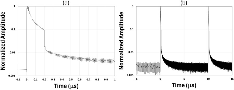
Figure 15. (a) Close-in and (b) zoom-out time domain trace for the highest power for run 3, 200 ns set pulse duration, 100 kHz repetition rate, and ∼160 W average power (normalized original data).
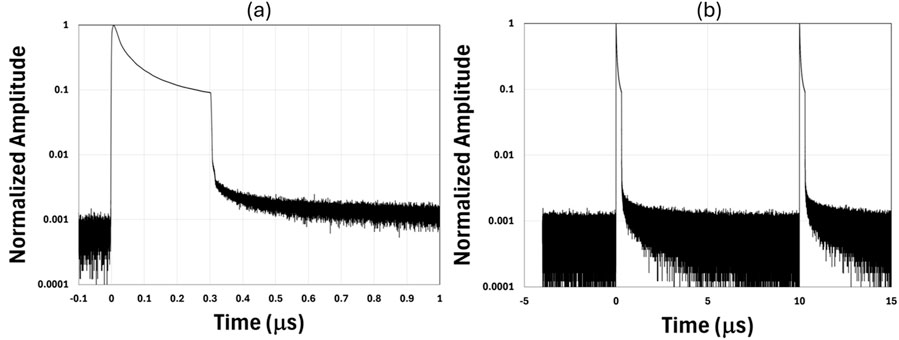
Figure 16. (a) Close-in and (b) zoom-out time domain trace for the highest power for run 4, 300 ns set pulse duration, 100 kHz repetition rate, and ∼150 W average power (normalized original data).

Figure 17. (a) Close-in and (b) zoom-out time domain trace for the highest power for run 5, 100 ns set pulse duration, 100 kHz repetition rate, and ∼150 W average power (normalized original data).
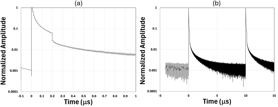
Figure 18. (a) Close-in and (b) zoom-out time domain trace for the highest power for run 6, 200 ns set pulse duration, 100 kHz repetition rate, and ∼200 W average power (normalized original data).
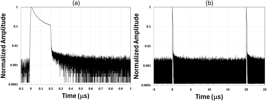
Figure 19. (a) Close-in and (b) zoom-out time domain trace for the highest power for run 7, 200 ns set pulse duration, 50 kHz repetition rate, and ∼190 W average power (normalized original data).
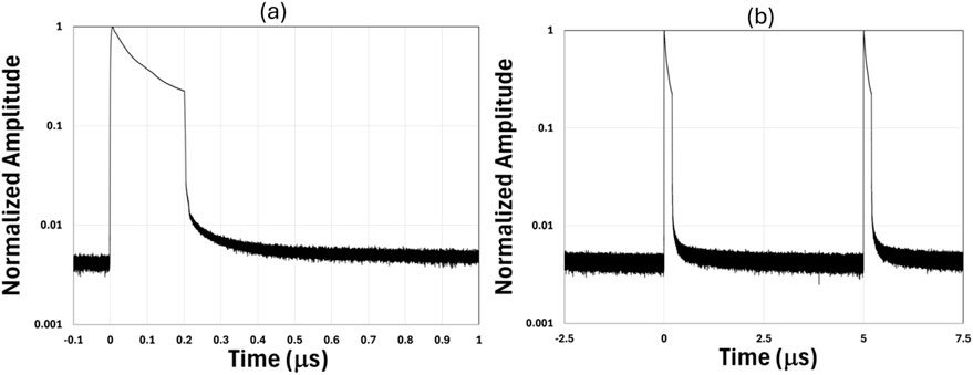
Figure 20. (a) Close-in and (b) zoom-out time domain trace for the highest power for run 8, 200 ns set pulse duration, 200 kHz repetition rate, and ∼120 W (average power (normalized original data).
We numerically integrated the measured optical power in the time domain for the highest powers for each run (data typically collected every 31.25 ps) to obtain the ratio of the energy inside the main pulse relative to the total pulse energy between rising edges of two consecutive pulses. The main pulse is defined as within the set duration of the pulse, marked by the arrow for the pulses set at 200ns duration in Figure 12a for an example. This definition allows an easy and unambiguous identification of the main pulse. The total energy is integrated over one entire period from pulse to pulse. The DC detection noise floor in each case is taken as the optical power just before the arrival of the pulse averaged over 1 μs The DC detection noise floor was first subtracted from the measured optical power and numerical integration was then performed in the time domain. The fraction of the total energy in the main pulse can then be obtained for each run at the maximum power. This is summarized in the third row of Table 3. Time domain data was not measured for the first and second runs. In general, the energy in the main pulse is between 1.7% in the eighth run to 30.4% in the fifth run according to the third row of the Tabel 3 below the total pulse energy calculated from the measured average power. The corrected pulse energy is given in the last row of Table 3.
In summary, the maximum pulse energy versus core diameter from our model seems to provide a reasonable guidance on the upper limit of pulse energy that can be extracted from a given fiber. Most data observed in the literature as well as the experimental study provided herein are consistent with the model. We conducted a systematic study of output pulse energy’s dependence on pulse durations, fiber lengths, and repetition rates and found our MOPA is primarily limited by fiber fuse at pulse energies roughly between 1 and 2 mJ in all the cases tested. Our two-stage diffraction-limited monolithic MOPA has achieved ∼20 ns FWHM pulses at ∼1.5 mJ, 100 kHz repetition rate and ∼200 W average power with M2 = ∼1.1, limited only by fiber fuse. The highest pulse energy obtained is ∼1.7 mJ within the main pulse. Both the pulse energies and average powers are among some of the highest for diffraction-limited monolithic fiber MOPA architectures thus providing some interesting potential for industrial lasers.
The raw data supporting the conclusions of this article will be made available by the authors, without undue reservation.
SB: Conceptualization, Data curation, Formal Analysis, Investigation, Methodology, Software, Validation, Visualization, Writing–original draft, Writing–review and editing. DM: Data curation, Funding acquisition, Investigation, Methodology, Resources, Writing–original draft, Writing–review and editing. MM: Data curation, Formal Analysis, Investigation, Methodology, Validation, Visualization, Writing–original draft, Writing–review and editing. TH: Investigation, Writing–original draft, Writing–review and editing. MK-D: Writing–original draft, Writing–review and editing, Investigation. JB: Funding acquisition, Investigation, Project administration, Resources, Supervision, Writing–original draft, Writing–review and editing. LD: Conceptualization, Formal Analysis, Funding acquisition, Methodology, Project administration, Resources, Supervision, Writing–original draft, Writing–review and editing.
The author(s) declare that financial support was received for the research and/or publication of this article. The authors would like to acknowledge financial support by United States Army Space and Missile Defense Command (Contracts AMTC-22–01–080/W9113M22D0061) as well as OUSD’s Joint Direct Energy Transition Office. SMDC PAO#4198 – Approved for public release and distribution on 2 December 2024.
The authors declare that the research was conducted in the absence of any commercial or financial relationships that could be construed as a potential conflict of interest.
The author(s) declare that no Generative AI was used in the creation of this manuscript.
All claims expressed in this article are solely those of the authors and do not necessarily represent those of their affiliated organizations, or those of the publisher, the editors and the reviewers. Any product that may be evaluated in this article, or claim that may be made by its manufacturer, is not guaranteed or endorsed by the publisher.
1. Dong L, Samson B. Fiber lasers: basics, Technology and applications. Boca Raton, FL: CRC Press (2017).
2. Renaud CC, Offerhaus HL, Alvarez-Charvez JA, Nilsson J, Clarkson WA, Turner PW, et al. Characteristics of Q-switched cladding-pumped ytterbium-doped fiber lasers with different high-energy fiber designs. IEEE J Quan Electron. (2001) 37:199–206. doi:10.1109/3.903069
3. Dong L. Nonlinear propagation in optical fibers with gain saturation and gain dispersion. IEEE J Lightwave Technol (2020) 38:6897–904. doi:10.1109/jlt.2020.3019972
4. Dudley JM, Taylor JR. Supercontinuum generation in optical fibers. New York, NY, USA: Cambridge Univ. Press (2010).
5. Kalichevsky-Dong MT, Ge W, Hawkins TW, Matniyaz T, Dong L. 4.8 mJ pulse energy directly from single-mode Q-switched ytterbium fiber lasers. Opt Express (2021) 29:30384–91. doi:10.1364/oe.438634
6. Glick Y, Pincha J, Kansal I, Windeler R, Lukonin V, Monberg E, et al. LMA fibers with increased higher-order mode loss for high average power, pulsed, diffraction-limited lasers. Opt Express (2024) 32:16688–701. doi:10.1364/oe.518422
7. Teodoro FD, Koplow JP, Moore SW, Kliner DAV. Diffraction-limited, 300-kW peak-power pulses from a coiled multimode fiber amplifier. Opt Lett (2002) 27:518–20. doi:10.1364/ol.27.000518
8. Farrow RL, Kliner DAV, Schrader PE, Hoops AA, Moore SW, Hadley GR, et al. High-peak-power (>1.2 MW) pulsed fiber amplifier. Proc SPIE (2006) 6102(61020L):61020L. doi:10.1117/12.646815
9. Khitrov V, Samson B, Machewirth D, Yan D, Tankala K, Held A. High peak power pulsed single-mode linearly polarized LMA fiber amplifier and Q-Switched laser. Proc SPIE (2007) 6453:645305.
10. Schrader PE, Farrow RL, Kliner DAV, Fève JP, Landru N. High-power fiber amplifier with widely tunable repetition rate, fixed pulse duration, and multiple output wavelengths. Opt Express (2006) 14:11528–38. doi:10.1364/oe.14.011528
11. Farrow RL, Kliner DAV, Schrader PE, Hoops AA, Moore SW, Hadley GR, et al. High-peak-power (>1.2MW) pulse fiber amplifier. Proc SPIE (2006) 6102:61020L.
12. Teodoro FD, Brooks CD. Multistage Yb-doped fiber amplifier generating megawatt peak-power, sub-nanosecond pulses. Opt Lett (2005) 30:3299–301. doi:10.1364/ol.30.003299
13. Teodoro FD, Brooks CD. 1-mJ energy, 1-MW peak-power, 10-W average power, spectrally narrow, diffraction-limited pulses from a photonic-crystal fiber amplifier. Opt Express (2005) 13:8999–9002. doi:10.1364/opex.13.008999
14. Teodoro FD, Brooks CD. 1.1 MW peak-power, 7 W average-power, high-spectral-brightness, diffraction-limited pulses from a photonic crystal fiber amplifier. Opt Lett (2005) 30:2694–6. doi:10.1364/ol.30.002694
15. Galvanauskas A, Sartania Z, Bischoff M. Millijoule femtosecond all-fiber system. In: Conference on laser and electro optics, paper CMA1 (2001).
16. Schrader PE, Feve JP, Farrow RL, Kliner DAV, Schmitt RL. Power scaling pf fiber-based amplifiers seeded with microchip lasers. Proc SPIE (2008) 6871:68710T.
17. Galvanauskas A, Cheng MY, Hou KC, Liao KH. High peak power pulse amplification in large-core Yb-doped fiber amplifiers. IEEE J Sel Top Quant Electron (2007) 13:559–66. doi:10.1109/jstqe.2007.899145
18. Röser F, Eidam T, Rothhardt J, Schmidt O, Schimpf DN, Limpert J, et al. Millimole pulse energy high repetition rate femtosecond fiber chirped-pulse amplification system. Opt Lett (2007) 24:3495–7. doi:10.1364/ol.32.003495
19. Klenke A, Hädrich S, Eidam T, Rothardt J, Kienel M, Demmler S, et al. 22GW peak-power fiber chirped-pulse-amplification system. Opt Lett (2014) 39:6875–8. doi:10.1364/ol.39.006875
20. Brooks CD, Teodoro FD. Multimegawatt peak-power, single-transverse-mode operation of a 100μm core diameter, Yb-doped rodlike photonic crystal fiber amplifier. Appl Phys Lett (2006) 89:111119. doi:10.1063/1.2348742
21. Patokoski K, Rissanen J, Noronen T, Gumenyuk R, Chamorovskii Y, Filippov V, et al. Single-frequency 100ns/0.5mJ laser pulses from all-fiber double-clad ytterbium doped tapered fiber amplifier. Opt Express (2019) 27:31532–41. doi:10.1364/oe.27.031532
22. Roy V, Grenier P, Desbiens L, Deshaies S, Deladurantaya M, Paradis P, et al. High-power/energy, large mode area tapered fiber amplifiers. Proc SPIE (2021) 11665:1166509.
23. Scol F, Bouwmans G, Hugonnot E. High-energy, narrow-linewidth, flat-top temporal profile nanosecond-pulses from ytterbium-doped tapered fiber amplifier with chirped-diode seeding. OSA Continuum (2021) 4:1162–9. doi:10.1364/osac.417479
24. Suzuki S, McKay HA, Peng X, Fu L, Dong L. Highly ytterbium-doped silica fibers with low photo-darkening. Opt Express (2009) 17:9924–32. doi:10.1364/oe.17.009924
25. Kashyap R. The Fiber Fuse - from a curious effect to a critical issue: a 25^th year retrospective. Opt Express (2013) 21:6422–41. doi:10.1364/oe.21.006422
26. Kong F, Dunn C, Parsons J, Kalichevsky-Dong MT, Hawkins TW, Jones M, et al. Large-mode-area fibers operating near single-mode regime. Opt Express (2016) 24:10295–301. doi:10.1364/oe.24.010295
27. Zhang H, Xiao H, Wang X, Zhou P, Xu X. Mode dynamics in high-power Yb-Raman fiber amplifier. Opt Lett (2020) 45:3394–7. doi:10.1364/ol.393879
28. Pavlov I, Dülgergil E, Ilbey E, Ilday FÖ. Diffraction-limited, 10-W, 5-ns, 100-kHz, all-fiber laser at 1.55 μm. Opt Lett (2014) 39:2695–8. doi:10.1364/ol.39.002695
Keywords: pulsed fiber laser, pulsed fiber amplifier, fiber amplifier, fiber laser, nanosecond (ns) laser
Citation: Bingham SP, Matyas D, Mihalik M, Hawkins TW, Kalichevsky-Dong MT, Ballato J and Dong L (2025) Output pulse energy from pulsed single-mode fiber amplifiers. Front. Phys. 13:1539099. doi: 10.3389/fphy.2025.1539099
Received: 03 December 2024; Accepted: 12 March 2025;
Published: 26 March 2025.
Edited by:
Rumao Tao, China Academy of Engineering Physics, ChinaReviewed by:
Zhimeng Huang, China Academy of Engineering physics, ChinaCopyright © 2025 Bingham, Matyas, Mihalik, Hawkins, Kalichevsky-Dong, Ballato and Dong. This is an open-access article distributed under the terms of the Creative Commons Attribution License (CC BY). The use, distribution or reproduction in other forums is permitted, provided the original author(s) and the copyright owner(s) are credited and that the original publication in this journal is cited, in accordance with accepted academic practice. No use, distribution or reproduction is permitted which does not comply with these terms.
*Correspondence: Samuel P. Bingham, c3BiaW5naEBnLmNsZW1zb24uZWR1
Disclaimer: All claims expressed in this article are solely those of the authors and do not necessarily represent those of their affiliated organizations, or those of the publisher, the editors and the reviewers. Any product that may be evaluated in this article or claim that may be made by its manufacturer is not guaranteed or endorsed by the publisher.
Research integrity at Frontiers
Learn more about the work of our research integrity team to safeguard the quality of each article we publish.