 Enxiang Qu
 Hui Qi1
- 1College of Aerospace and Civil Engineering, Harbin Engineering University, Harbin, Heilongjiang, China
- 2School of Architecture and Civil Engineering, Qiqihar University, Qiqihar, Heilongjiang, China
In this paper, the dynamic issue related to a semicircular depression in a piezoelectric ceramic plate is investigated. The fundamental mechanical problems of dynamic stress concentration factor and electric field intensity concentration factor are addressed using the complex function approach, wave function expansion method, and repeated mirror method, and the analytical expressions for the relevant stress concentration are presented. The influences of the dimensionless parameter wave number, strip thickness, and guided wave order on the stress concentration of the SH guided wave incident within the strip are explored.The results indicate that, with a fixed plate thickness, the 0 order high frequency guided wave exerts a more pronounced influence on the stress concentration near the hole, resulting in more severe damage. Under the electromechanical coupling effect, the detrimental impact of the electric field far exceeds that of the stress field. Consequently, it is essential to focus on the adverse effects imposed by the electric field.
1 Introduction
Piezoelectric ceramics possess extraordinary electromechanical coupling properties and hold an irreplaceable value both in scientific research and practical applications. In terms of research significance, they provide a crucial path for exploring the inherent relationship between the micro - structure and macroscopic properties of materials. This helps to deepen the understanding of the physical properties of crystals and promote the development of basic sciences. In the energy field, the energy - harvesting potential of piezoelectric ceramics is expected to relieve the energy pressure and make self - powered devices possible. At the application level, piezoelectric ceramics can accurately measure parameters such as pressure and acceleration, serving key scenarios like aerospace and automotive safety. In ultrasonic technology, they enable efficient cleaning and precision machining. In the medical field, ultrasonic diagnostic and therapeutic equipment, by leveraging piezoelectric ceramics, achieve accurate disease detection and treatment, greatly enhancing the medical level and efficiency. However, during the design and use of piezoelectric ceramic structures, a series of problems such as void defects often occur. The existence of defects at the boundaries can lead to brittle fracture and failure of the structure. This paper conducts research on the problem of open holes at the boundaries of strip - shaped piezoelectric ceramic structures, taking advantage of the SH guided wave, which features fast propagation speed, high detection efficiency, low attenuation, and strong applicability.
In recent years, the application of equipment made of piezoelectric ceramics has been widely concerned in structural damage detection.Miao et al. [1] introduced a double-layer metasurface aimed at isolating the fundamental shear horizontal wave (SH0 wave). Dutta et al. [2] presented a novel study comparing the effects of single and dual porosity on the propagation of horizontally polarized shear waves (SH waves) in corrugated elastic void materials. Hu et al. [3] studied the propagation of SH waves in elastic semi-infinite media with semi-elliptical craters on the surface. Hemalatha et al. [4] analyzed and studied SH waves in a rotating functionally graded magnetoelectroelastic system composed of an elastic substrate and a linearly changing functionally graded magnetoelectroelastic layer. Wang et al. [5] improved the damage imaging accuracy of anisotropic plates with uniform thickness and variable thickness by combining a new compensation term based on the theoretical excitation directivity of quasi-SH0 modes in anisotropic materials. The MSBPT proposed by Miao et al. [6] is composed of a meta-substrate two-column thickness shear mode PZT wafer, which is achieved by developing a unidirectional SH0 deflection of a substrate-based piezoelectric transducer under a single driving source. Qu et al. [7] studied the dynamic stress concentration coefficient of a semi-cylindrical depression on the surface of an infinite elastic plate under the action of SH-waves and gave an analytical solution. Li et al. [8] used the complex function method to study wave propagation in a non-uniform half-space with semi-cylindrical surface bumps. Guo et al. [9] investigated theoretical methods, function expansion method, complex mirror image method and other methods to study the wave scattering problem in an elastic half-space anisotropic medium containing a semicircular canyon and a movable cylindrical cavity. Qi et al. [10–13] conducted a systematic and comprehensive study on the theoretical models of half space, infinite space, and semi-infinite space that contain holes and inclusions, thereby providing a valuable theoretical foundation for understanding the wave field. Sun et al. [14] examined the displacement amplitude at the interface of an elastic half-space with a semicircular depression covered by a viscous liquid under the action of shear horizontal waves. Zhang et al. [15] considered the exponential distribution of material parameters along the coordinate axis and studied the dynamic characteristics of a circular inclusion in an inhomogeneous piezomagnetic half-space with anti-plane shear wave propagation. Using the theory of complex variables in plane elasticity, Liu et al. [16] proposed a wave function expansion method to analyze the external scattering of SH wave surfaces caused by two symmetrical circular cavities situated in two bonded exponentially graded half-spaces. Li et al. [17] discussed in detail the effects of magnetic field and compressive stress on the mechanical displacement, dynamic stress and magnetic potential of the SH wave around the circular hole. Kuo et al. [18] proposed an exact analysis for the scattering of anti-plane shear wave by a piezoelectric circular cylinder in piezomagnetic matrix with imperfect interfaces. Yang et al. [19] used complex functions and Green’s method to study the dynamic anti-plane characteristics of collinear periodic cracks at Type III interfaces in a bi-material half-space. Singh et al. [20] examined the scattering of Love waves in interface cracks in thin lossy media (viscoelastic materials).The fracture and scattering problems of piezoelectric quasicrystals [21–27] have also received extensive attention. Research in this area has significantly enriched the applications of piezoelectric materials.
The research on boundary perforations in strip - shaped piezoelectric ceramic structures holds immense significance and remarkable value. In the realm of fundamental research, the presence of boundary perforations modifies the stress distribution and vibration characteristics within piezoelectric ceramics. This not only facilitates a profound comprehension of the microscopic mechanisms underlying the piezoelectric effect but also furnishes a theoretical foundation for the optimization of material properties. In the field of acoustics, the insights derived from the study of this model can serve as crucial theoretical references. They play a pivotal role in optimizing the performance of ultrasonic transducers, enhancing the precision of medical imaging techniques, and improving the efficacy of non - destructive testing methods.
2 Steady state governing equation
Assuming that the Z-axis is the direction of electrical polarization, the steady-state control Equation of the infinitely long ceramic piezoelectric medium is Equation 1.
Substitute Equation 2 into Equation 1 and further simplify it to Equation 3.
There is a relationship in the above Equation:
In the polar coordinate system
In the polar coordinate system
In the complex plane
3 Structure model
The initial defects of the piezoelectric ceramic plate strip structure do not always occur inside the strip structure. Defects at the edge positions also happen from time to time.To effectively study the damage of piezoelectric ceramic plates, this paper analyzes the problem of a semi - circular hole being drilled at the edges of the piezoelectric strip.The structural model of an infinitely long piezoelectric ceramic plate containing a semi-cylindrical depression is shown in Figure 1. The radius of semicircular recess is
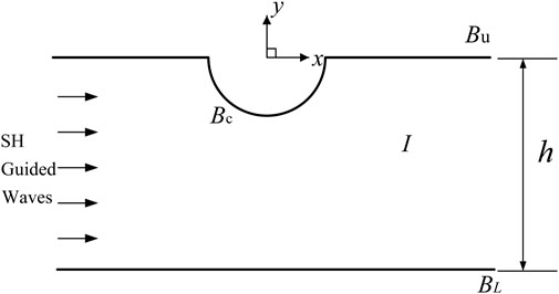
Figure 1. An infinite length piezoelectric ceramic plate structure model with a semi-cylindrical depression.
4 Wave field in a slab structure
4.1 Incident wave field in a piezoelectric ceramic plate structure
The SH guided wave expression is shown in Equation 7.
The upper and lower boundaries of the piezoelectric ceramic lath structure satisfy stress freedom and electrical insulation conditions as shown in Equation 8.
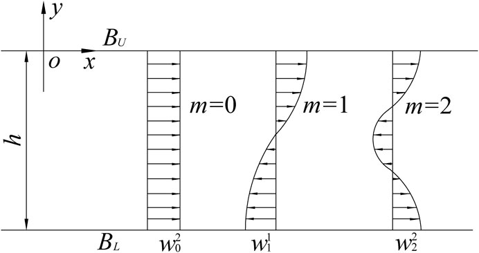
Figure 2. Mode of SH guided wave.
The condition that
By superimposing the guided waves, all displacement waves that comply with the stress-free and electrically insulated conditions of the upper and lower boundaries of the strip piezoelectric material medium can be derived, as illustrated in Equation 12.
The displacement is expressed as Equation 13.
The stress is expressed as Equation 14.
The polar coordinate expression of stress is Equation 15.
4.2 Scattered wave field in a piezoelectric ceramic plate structure
The expression for scattered waves in the elastic wave field is Equation 16.
Using the mirror image method, the scattered guided wave is
When
When
When
The scattered wave expression of the elastic wave field is Equation 21.
The potential expression for the scattered wave and its excitation is Equation 22.
The specific expression of
When
When
The displacement and potential expression of medium I in the infinitely long piezoelectric ceramic plate structure is Equation 26.
4.3 Wavefield in the depression
There is only electric field but no elastic field in the depression. The potential inside the hole satisfies the Laplace Equation
5 Boundary conditions and definite solutions to the system of integral equations
The boundary conditions for stress freedom, potential and normal electric displacement continuity are Equation 28.
The definite solution integral Equation set established from Equation 28 is as follows Equation 29.
Multiply the left and right sides of Equation system (29) by
Where
Equation 30 is an infinite system of Equations for solving the coefficients
6 Stress concentration
The dynamic stress concentration factor can be expressed as Equation 31.
Where
The electric field intensity coefficient can be expressed as Equation 32.
Among them
7 Results and analysis
This paper uses dimensionless parameter analysis. Since the dielectric constant of most piezoelectric media is three orders of magnitude greater than that of a cavity (vacuum or air),
Figure 3 discusses the stress concentration at the hole edge as a function of h* for ka = 0.5 and m = 1. It can be seen from the figure that the electric field intensity concentration coefficient at the hole edge is obviously greater than the dynamic stress concentration coefficient. When h* = 3, the maximum value of the electric field intensity coefficient at the edge of the recess is about 2.5 times larger than the maximum value of the dynamic stress coefficient. With the increase of dimensionless h*, the stress concentration coefficient at the edge of the hole tends to weaken. The value corresponding to h* = 3 is 5.18 times higher than that corresponding to h* = 10.The value corresponding to h* = 3 is 5.02 times higher than that corresponding to h* = 10. It is not difficult to see that the distance of the lower boundary has a significant reduction in the stress concentration at the hole edge. When the thickness of the ceramic piezoelectric plate reaches a certain value, the stress concentration distribution gradually becomes a regular circle, which is basically close to about 270°. When SH guided waves impinge upon piezoelectric ceramic structures harboring defects, due attention must be accorded to the harm inflicted by electric fields. In the event of structural damage, appropriately regulating the plate thickness can effectively mitigate stress concentration, thereby safeguarding the piezoelectric ceramic plate from being damaged.
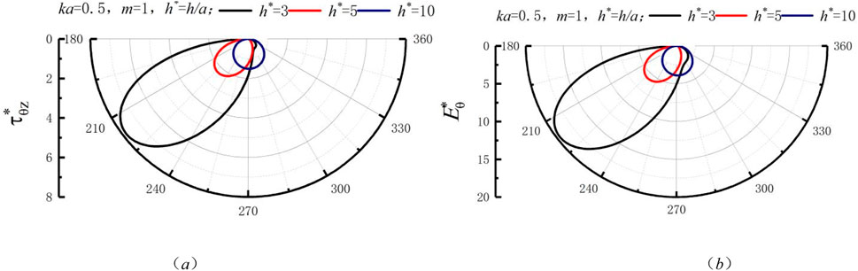
Figure 3. Distribution of stress around the depression with h* when ka = 0.5: (A) Dynamic stress concentration coefficient (B) Electric field intensity concentration coefficient.
Figure 4 shows the change of stress concentration at the hole edge with h* when m = 1 and ka = 1.0. It is different from the physical phenomenon in Figure 3. When h* = 3, the stress concentration at the edge of the depression decreases significantly and the stress distribution diagram is no longer a single petal. As h* increases, the stress concentration does not always decrease but reaches a maximum at h* = 5. As h* increases, the stress concentration factor gradually approaches from the facing wave surface to the back wave surface. When it increases to a certain value, it is basically close to the position directly below the concave edge. It can be concluded that when designing this kind of ceramic piezoelectric plate. If there is a depression on the boundary, it is not always the most dangerous right below the hole edge. The electric field strength at the hole edge is still greater than the dynamic stress. Similarly, in engineering practice, we should still focus on the adverse effects of the electric field.
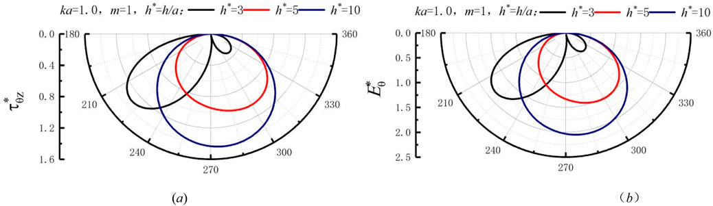
Figure 4. Distribution of stress around the depression with h* when ka = 1.0: (A) Dynamic stress concentration coefficient (B) Electric field intensity concentration coefficient.
Figure 5 shows the change of stress concentration at the hole edge with h* when m = 1 and ka = 1.5. Figure 5 can see that as h* increases. Both
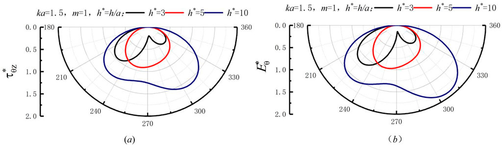
Figure 5. Distribution of stress around the depression with h* when ka = 1.5: (A) Dynamic stress concentration coefficient (B) Electric field intensity concentration coefficient.
Figure 6 shows the change of stress concentration at the hole edge with h* when m = 1 and ka = 2.0. It can be seen from the figure that the electric field intensity concentration coefficient at the edge of the recess increases little compared with the dynamic stress concentration coefficient. The impact and changes of the two are basically the same. As h* increases, the values of
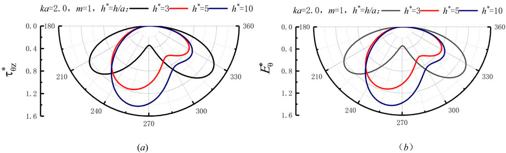
Figure 6. Distribution of stress around the depression with h* when ka = 2.0: (A) Dynamic stress concentration coefficient (B) Electric field intensity concentration coefficient.
Figure 7 shows the change of stress concentration at the hole edge with the guided wave order m when h* = 5 and ka = 0.5. Figure 7A shows that the dynamic stress concentration coefficient at the recessed edge increases as the number of guided waves increases. The maximum value
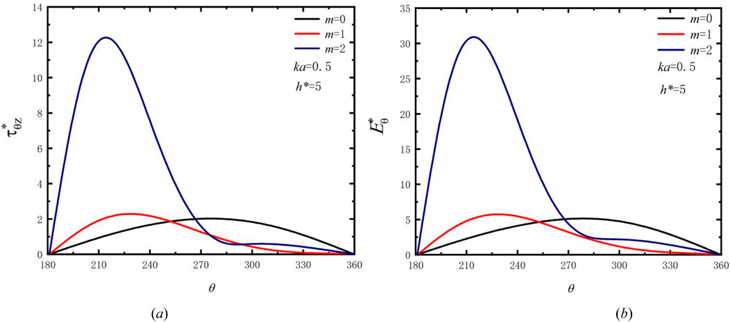
Figure 7. Distribution of stress around the depression with guided wave order m when ka = 0.5: (A) Dynamic stress concentration coefficient (B) Electric field intensity concentration coefficient.
Figure 8 shows the change of stress concentration at the hole edge with the guided wave order m when h* = 5 and ka = 1.0. The
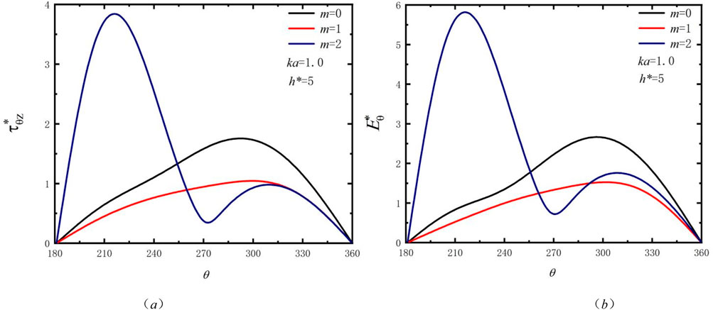
Figure 8. Distribution of stress around the depression with guided wave order m when ka = 1.0. (A) Dynamic stress concentration coefficient (B) Electric field intensity concentration coefficient.
Figure 9 shows the change of stress concentration at the hole edge with the guided wave order m when h* = 5 and ka = 1.5. The dynamic stress and electric field strength at the edge of the hole have basically the same trend with the number of guided waves. When the guided wave order m = 0, the peaks of
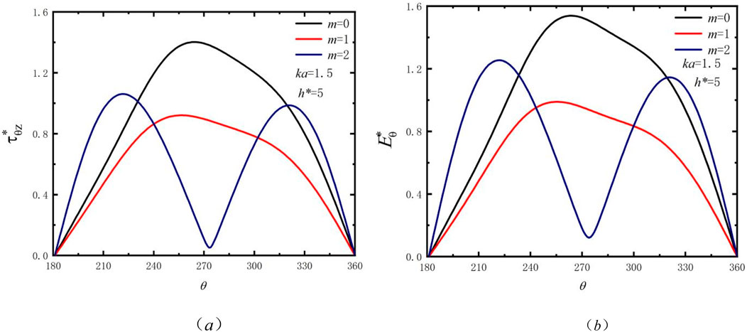
Figure 9. Distribution of stress around the depression with waveguide order m when ka = 1.5: (A) Dynamic stress concentration coefficient (B) Electric field intensity concentration coefficient.
Figure 10 shows how the stress concentration at the hole edge changes with the guided wave order m when h* = 5 and ka = 2.0. Under the action of mechano-electric coupling, the changing trends of the dynamic stress coefficient and the electric field intensity coefficient at the hole edge are similar. The effect of electric field is not significantly greater than that of force. The stress concentration caused by the incidence of 0th-order guided waves is significantly higher than that of first-order and second-order guided waves and shows a weakening trend. The order in which stress concentration reaches its peak is second order, first order and 0th order, all showing the trend of oscillation attenuation. Under the influence of this frequency band, the impact of the 0th-order guided wave incidence is more serious.
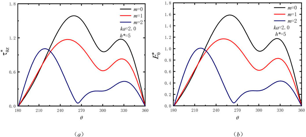
Figure 10. Distribution of stress around the depression with waveguide order m when ka = 2.0: (A) Dynamic stress concentration coefficient (B) Electric field intensity concentration coefficient.
8 Conclusion
In this paper, based on the wave theory of SH guided waves, the complex variable function method, repeated image method and guided wave expansion method are used to study the stress concentration problem at the hole edge. The effects of dimensionless parameters ka, h* and order m on the dynamic stress coefficient and electric field intensity concentration coefficient at the hole edge are discussed. Relevant conclusions are drawn to protect the safe use of piezoelectric ceramic plate structures.
(1) When the first-order guided wave is incident, the wave number ka = 0.5, and the plate thickness is relatively thick, the stress concentration at the edge of the hole can be effectively reduced, paying special attention to the influence under the action of the electric field. When the wave number ka > 0.5 and the plate thickness is relatively thin, the reduction of stress at the hole edge will cause less damage to the ceramic piezoelectric plate. Therefore, under different wave numbers, the plate thickness needs to be reasonably controlled to protect the piezoelectric ceramic element from damage.
(2) When the plate thickness is constant, the wave numbers are ka = 0.5 and ka = 1.0 respectively, and the impact of the incident high-order guided waves is significantly higher than that of the low-order guided waves. When ka = 1.5 and ka = 2.0, the impact of the zero-order guided wave incidence on the stress concentration at the hole edge is more obvious, resulting in more serious damage. For different wave numbers SH guided waves incident, reasonable selection of the guided wave order can reduce the stress concentration to a certain extent.
(3) The laws governing the influence of plate thickness, wave number, and guided wave order are not static. The dimensionless parameters under discussion must be deliberated in light of specific conditions. Generally, under the force electricity coupling, the damage to ceramic piezoelectric plates induced by electric fields is comparatively more significant. Therefore, greater emphasis should be placed on the impact of electric fields.
Data availability statement
The raw data supporting the conclusions of this article will be made available by the authors, without undue reservation.
Author contributions
EQ: Funding acquisition, Software, Writing–original draft. HQ: Data curation, Writing–review and editing. JG: Validation, Writing–review and editing. SL: Methodology, Software, Writing–review and editing. YL: Resources, Investigation, Writing–original draft.
Funding
The author(s) declare that financial support was received for the research, authorship, and/or publication of this article. This work was supported by the National Natural Cultivation General Project of Basic Scientific Research Operating Expenses for Universities in Heilongjiang Province (145409328).
Conflict of interest
The authors declare that the research was conducted in the absence of any commercial or financial relationships that could be construed as a potential conflict of interest.
Generative AI statement
The author(s) declare that no Generative AI was used in the creation of this manuscript.
Publisher’s note
All claims expressed in this article are solely those of the authors and do not necessarily represent those of their affiliated organizations, or those of the publisher, the editors and the reviewers. Any product that may be evaluated in this article, or claim that may be made by its manufacturer, is not guaranteed or endorsed by the publisher.
References
1. Miao H, Cao X, Fu M. Double-layer metasurface for blocking the fundamental SH wave. Smart Mater Structures (2024) 33(9):095044. doi:10.1088/1361-665X/ad7215
2. Dutta R, Das S, Ahmad H, Gupta V. Comparative analysis of double and single porosity effects on SH-wave induced vibrations in periodic porous lattices. Soil Dyn Earthquake Eng (2024) 186:108919. doi:10.1016/j.soildyn.2024.108919
3. Hu H, Dai M, Gao CF. Scattering of SH wave in an elastic half-space by a semi-elliptical crater with surface elasticity. Appl Math Model (2024) 135:759–71. doi:10.1016/j.apm.2024.07.017
4. Hemalatha K, Kumar S. Propagation of SH-wave in a rotating functionally graded magneto-electro-elastic structure with corrugated interface. Mech Sol (2024) 59(3):1635–58. doi:10.1007/s42417-024-01365-5
5. Wang J, Li B. SH-wave based defect imaging method for CFRP plates with variable thickness. Nondestructive Test Eval (2024) 1-27:1–27. doi:10.1080/10589759.2024.2358384
6. Miao H, Du Y. Metasubstrate-based SH guided wave piezoelectric transducer for unidirectional beam deflection without time delay. Smart Mater Structures (2024) 33(1):015038. doi:10.1088/1361-665X/ad1890
7. Qu E, Qi H, Guo J, Wang L, Yang J, Liu S. Dynamic response analysis of SH-guided waves in a strip-shaped elastic medium for a semi-cylindrical depression. Archive Appl Mech (2023) 93(3):1241–58. doi:10.1007/s00419-022-02325-9
8. Li X, Song Y, Yang Z, Carrera E. Scattering of SH waves by a semi-cylindrical bump in an inhomogeneous half-space. Int J Appl Mech (2023) 15(04):2250034. doi:10.1142/S175882512250034X
9. Guo D, Bian J, Song Y, Yang Y, Yang Z. Response of semicircular canyons and movable cylindrical cavities to SH waves in anisotropic half-space geology. Geophysics (2024) 89(5):C197–C209. doi:10.1190/geo2023-0598.1
10. Qi H, Chu F, Guo J, Yang R. Surface motion of a half-space containing an elliptical-arc canyon under incident SH waves. Mathematics (2020) 8(11):1884. doi:10.3390/math8111884
11. Hui Q, Fuqing C, Jing G. Dynamic stress concentration of an elliptical cavity in a semi-elliptical hill under SH-waves. Earthquake Eng Eng Vibration (2021) 20:347–59. doi:10.1007/s11803-021-2024-9
12. Qi H, Xiang M, Guo J. The dynamic stress analysis of an infinite piezoelectric material strip with a circular cavity. Mech Adv Mater Structures (2021) 28(17):1818–26. doi:10.1080/15376494.2019.1709676
13. Fan Z, Qi H, Zhang Y, Wu H, Chu F, Guo J. Anti-plane dynamic response characteristics of a semi-infinite plate with cylindrical hole defect. Thin-Walled Structures (2024) 202:112038. doi:10.1016/j.tws.2024.112038
14. Sun B, Guo J, Zhang M, Zhang G. Dynamic response of a half-space with a depression covered by viscous liquid under SH waves. Soil Dyn Earthquake Eng (2022) 154:107139. doi:10.1016/j.soildyn.2021.107139
15. Zhang X, Qi H. Propagation of SH-waves in inhomogeneous piezoelectric/piezomagnetic half-space with circular inclusion. Acta Mechanica (2022) 233(9):3829–52. doi:10.1007/s00707-022-03315-2
16. Liu Q, Zhao M, Liu Z. Wave function expansion method for the scattering of SH waves by two symmetrical circular cavities in two bonded exponentially graded half spaces. Eng Anal Boundary Elem (2019) 106:389–96. doi:10.1016/j.enganabound.2019.05.015
17. Li Q, Gu C, Lei D, Ou Z. Scattering of shear horizontal (SH) waves by a circular hole in an infinite piezomagnetic material. Acta Mechanica Solida Sinica (2024) 1-12:891–902. doi:10.1007/s10338-024-00508-1
18. Kuo HY, Yu SH. Effect of the imperfect interface on the scattering of SH wave in a piezoelectric cylinder in a piezomagnetic matrix. Int J Eng Sci (2014) 85:186–202. doi:10.1016/j.ijengsci.2014.08.006
19. Yang J, Liu S, Liu Y, Yang B. Dynamic stress intensity factor for periodic interfacial cracks in a bi-material half space disturbed by SH waves. J Electromagn Waves Appl (2022) 36(18):2769–84. doi:10.1080/09205071.2022.2106901
20. Singh S, Saw GR, Chakraborty G. Scattering of Love wave from an interface crack in a viscoelastic waveguide layer bonded to a piezoelectric substrate: an analytical estimate and numerical validation. Mech Adv Mater Structures (2024) 31(16):3875–88. doi:10.1080/15376494.2023.2186547
21. Yang J, Xu Y, Ding S, Li X. Dynamic fracture of a partially permeable crack in a functionally graded one-dimensional hexagonal piezoelectric quasicrystal under a time-harmonic elastic SH-wave. Mathematics Mech Sol (2023) 28(9):1939–58. doi:10.1177/10812865221138838
22. Yang Z, Yu X, Xu W, Xu C, Zhou Z. Accurate fracture analysis of electrically permeable/impermeable cracks in one-dimensional hexagonal piezoelectric quasicrystal junction. Mathematics Mech Sol (2019) 24(12):4032–50. doi:10.1177/1081286519865002
23. Ma Y, Zhao X, Lu S, Yang J, Zhou Y, Ding S. Dynamic behavior of interface cracks in 1D hexagonal piezoelectric quasicrystal coating–substrate structures subjected to plane waves. J Eng Mech (2024) 150(12):04024090. doi:10.1061/JENMDT.EMENG-7808
24. Liu Y, Tang X, Duan P, Wang T. Three-dimensional thermo-electro-elastic field in one-dimensional hexagonal piezoelectric quasi-crystal weakened by an elliptical crack. Mathematics Mech Sol (2022) 27(7):1233–54. doi:10.1177/10812865211059219
25. Ma Y, Zhou Y, Yang J, Lu S, Zhao X, Ding S. Scattering of plane waves from an interface crack between the 1D hexagonal quasicrystals coating and the elastic substrate. Acta Mechanica (2024) 236:289–303. doi:10.1007/s00707-024-04153-0
26. Hu K, Yang W, Fu J, Chen Z, Gao CF. Analysis of an anti-plane crack in a one-dimensional orthorhombic quasicrystal strip. Mathematics Mech Sol (2022) 27(11):2467–79. doi:10.1177/10812865211073814
Keywords: piezoelectric ceramic, dynamic stress concentration factor, electric field intensity concentration factor, SH wave guide, electromechanical coupling effect
Citation: Qu E, Qi H, Guo J, Liu S and Li Y (2025) Scattering and stress concentration of SH guided waves by a semicircular hole on the boundary of an infinite piezoelectric ceramic plate. Front. Phys. 13:1527682. doi: 10.3389/fphy.2025.1527682
Received: 13 November 2024; Accepted: 04 February 2025;
Published: 12 March 2025.
Edited by:
Viacheslav Slesarenko, University of Freiburg, GermanyReviewed by:
Dabin Lin, Xi’an Technological University, ChinaEmad Awad, Alexandria University, Egypt
Copyright © 2025 Qu, Qi, Guo, Liu and Li. This is an open-access article distributed under the terms of the Creative Commons Attribution License (CC BY). The use, distribution or reproduction in other forums is permitted, provided the original author(s) and the copyright owner(s) are credited and that the original publication in this journal is cited, in accordance with accepted academic practice. No use, distribution or reproduction is permitted which does not comply with these terms.
*Correspondence: Enxiang Qu, MDMzMThAcXFocnUuZWR1LmNu
†ORCID: Enxiang Qu, orcid.org/0000-0001-5934-8253