 Yongcun Shao
 Yutong Cui
95% of researchers rate our articles as excellent or good
Learn more about the work of our research integrity team to safeguard the quality of each article we publish.
Find out more
ORIGINAL RESEARCH article
Front. Phys. , 07 April 2025
Sec. Interdisciplinary Physics
Volume 13 - 2025 | https://doi.org/10.3389/fphy.2025.1521849
This article is part of the Research Topic Nonlinear Vibration and Instability in Nano/Micro Devices: Principles and Control Strategies View all 16 articles
Introduction: Microelectromechanical systems (MEMS) are pivotal in diverse fields such as telecommunications, healthcare, and aerospace. A critical challenge in MEMS devices is accurately determining the pull-in displacement and voltage, which significantly impacts device performance. Existing methods, including the variational iteration method and homotopy perturbation method, often fall short in providing precise estimations of these parameters.
Methods: This study introduces a novel mathematical approach that combines physical insights into the pull-in phenomenon with variational theory. The method begins with a precise definition of the MEMS device's physical model. By uniquely applying the variational principle and incorporating a custom-designed functional, a set of equations is derived. These equations are transformed into an iterative algorithm for calculating pull-in displacement, with nonlinear terms addressed through approximation and perturbation techniques tailored to the MEMS system’s characteristics.
Results: Validation using specific examples demonstrates the method's accuracy in determining pull-in displacement and voltage. For instance, in a MEMS oscillator case, exact results were achieved with a computation time of 0.015 s. Compared to traditional methods, this approach yields exact values rather than approximations, showcasing superior precision and efficiency.
Discussion: The proposed method offers significant advantages, including enhanced accuracy, reduced computational time, and minimized error accumulation by solving algebraic equations instead of iterating differential equations. It also exhibits robustness to variations in initial conditions and system parameters. Limitations include the need for modifying the pull-in criterion when variational formulation is unattainable and the exclusion of environmental factors like temperature and pressure fluctuations. Future research should focus on refining MEMS models to incorporate these factors and integrating the approach with techniques such as Galerkin technology.
Conclusion: This research advances the mathematical understanding of MEMS device behavior and holds substantial potential for the design and optimization of MEMS devices across various applications, further driving the progression of MEMS technology.
Recent decades have seen a remarkable development in microelectromechanical systems (MEMS) [1, 2]. These systems integrate mechanical and electrical components at a microscopic level, enabling a diverse range of functions. In the telecommunications industry, MEMS-based devices are widely used in mobile phones and communication modules [3, 4]. For instance, MEMS sensors play a crucial role in signal filtering and sensing, enhancing the performance of communication devices. In the field of healthcare, MEMS technology finds application in implantable sensors for monitoring physiological parameters such as heart rate and blood pressure, as well as in lab-on-a-chip systems for rapid medical diagnostics [5, 6]. In the aerospace industry, MEMS sensors are utilized for aircraft performance monitoring, and micro-actuators are employed for precise control of spacecraft components [7, 8]. The prevalence of MEMS technology in various fields underscores the necessity for continuous enhancement of device performance. Among the various characteristics of MEMS devices, the pull-in instability [9, 10] is a critical parameter that significantly influences their performance and functionality.
Pull-in instability [9, 10] is a pivotal factor that exerts a considerable influence on the performance and reliability of MEMS devices. It is directly related to the critical parameters of pull-in displacement and voltage [11, 12].To illustrate this, consider MEMS oscillators. As the applied voltage rises, the electrostatic forces between the movable and fixed parts can induce substantial deformation. The voltage threshold at which pull-in instability occurs is a critical factor in the design of MEMS devices, as it can lead to a sudden collapse of the device structure. This instability can have a significant impact on the long-term durability and accuracy of the device, as well as its ability to function properly under different operating conditions. Therefore, it is essential to develop a precise understanding of the relationship between pull-in displacement and voltage to optimize the design of MEMS devices and ensure their reliable performance.
As outlined in references [13–16], the variational iteration method is one of the approaches to be considered in this regard. However, it is a highly intricate process to identify the Lagrange multiplier. This identification requires an in-depth comprehension of the system’s dynamics and the underlying mathematical relationships, making it both complex and time-consuming. Since the accurate determination of the Lagrange multiplier is crucial for attaining precise outcomes, it frequently presents significant challenges in practical scenarios.
The homotopy perturbation method (HPM) [17, 18] has also been shown to have certain limitations. The application of the HPM requires two things: firstly, a well-constructed homotopy equation and secondly, a reliable initial guess. Formulating an appropriate homotopy equation is challenging, as it must precisely encapsulate the behavior of the system. Additionally, obtaining a good initial guess, as discussed in [19], often relies heavily on prior knowledge and experience. Erroneous initial estimates can invariably yield erroneous outcomes. To address these limitations, a combination of the homotopy perturbation method and the Laplace transform has been proposed for solving MEMS oscillators, as reported in [20].
The application of ancient mathematics to MEMS systems has recently attracted considerable attention on account of its effectiveness and simplicity, as evidenced in [21–23].Significantly, the point-solution method [24] and the Anjum-He method based on Sturm’s algorithm [25] have emerged as promising techniques for rapidly and accurately identifying the pull-in voltage. Furthermore, the advent of AI-powered problem-solving techniques has opened up new avenues for the resolution of complex MEMS systems [26].
The frequency formulation [27, 28] presents an alternative approach that offers simplicity and straightforwardness. It provides a relatively uncomplicated way to approach the problem. However, it is not an iteration method. The absence of an iterative process means that further improvement of its accuracy becomes challenging. Once the initial formulation is set, there are limited options for refining the results, making it difficult to achieve the high precision required for advanced MEMS device applications.
In the realm of MEMS device research and application, the accurate determination of pull - in displacement or pull - in voltage is of paramount importance. MEMS devices are playing an increasingly significant role in numerous fields. The pull - in displacement, as a pivotal parameter influencing their performance, renders its precise determination highly essential. When the pull - in voltage approaches a specific threshold, the system becomes acutely sensitive. Even a minute perturbation can cause the device’s dynamic characteristics to shift abruptly from stable periodic motion to pull - in instability, which can severely disrupt the device’s normal operation and degrade its performance.
Currently, although various analytical methods can estimate an approximate pull - in voltage for MEMS systems, such approximate results are insufficient to meet the ever - growing demand for high precision. Consequently, the exact determination of the pull - in voltage has emerged as a crucial issue in both theoretical analysis and practical applications.
In response to the challenges identified, this research endeavor seeks to formulate a novel mathematical approach for the expeditious and precise estimation of pull-in displacement in MEMS devices. The proposed method integrates sophisticated analytical techniques and pioneering algorithms, leveraging the variational principle in an original manner and introducing innovative computational strategies to circumvent the constraints imposed by conventional methodologies. The devised approach is engineered to achieve substantial enhancements in the efficiency and precision of pull-in displacement estimation. This will not only deepen our understanding of MEMS device behavior from a mathematical perspective but also hold great potential for facilitating the design and optimization of MEMS devices in various fields, thus contributing to the advancement of MEMS technology.
The pull-in phenomenon in MEMS represents a highly intricate physical process. In essence, in an electrostatically actuated MEMS device, the delicate balance between the mechanical and electrical forces within the system is disrupted when an external electrical stimulus, such as an increasing voltage, is applied. As the voltage ascends towards a critical value, the electrostatic forces start to preponderate, compelling the movable parts of the device to swiftly approach the fixed parts. This abrupt movement is precisely the pull-in instability. Mathematically, this process can be described by a set of equations that intricately link the displacement, velocity, and acceleration of the movable components to the applied voltage and the mechanical attributes of the device. For instance, in a basic MEMS oscillator model, the relationship among these variables is manifested through differential equations that govern the dynamic behavior of the system.
The periodic criterion is of fundamental importance in the analysis of the dynamic behavior of MEMS systems, and is inextricably linked to the pull-in criterion. In a MEMS oscillator, when the periodic criterion is fulfilled, the system exhibits stable oscillatory behavior, characterized by a particular relationship between the acceleration and displacement of the movable part, where their directions are consistently opposed during the oscillatory state. However, as conditions deviate from the periodic criterion and edge closer to the pull-in condition, the system’s behavior undergoes a significant transformation. The pull-in criterion delineates the conditions under which the system becomes unstable and the pull-in eventuates. By meticulously analyzing the transition from the periodic behavior to the pull-in behavior using mathematical models, we can attain a more profound understanding of the underlying mechanisms. This enhanced knowledge can then be applied to the development of effective methods for predicting and controlling the pull-in phenomenon.
Pull-in instability is a phenomenon that frequently manifests in certain mechanical and electrical systems. Essentially, it transpires when a system is subjected to an external force or stimulus and reaches a critical juncture where it suddenly experiences a breakdown or becomes unstable. This is vividly exemplified in microelectromechanical systems (MEMS).As the applied voltage mounts, the electrostatic force between the movable and fixed parts of a MEMS device may induce deformation. At a particular voltage threshold, the pull-in instability is initiated, leading to the swift collapse of the device. A comprehensive and in-depth understanding of pull-in instability is of the utmost importance for the design and operation of a wide range of advanced technologies. Engineers must accurately anticipate and appropriately consider this instability to ensure the reliability and optimal performance of their systems. By systematically investigating the factors that influence pull-in instability, such as material properties, geometry, and operating conditions, researchers can formulate strategic approaches to either mitigate this phenomenon or exploit it for specific applications. This facilitates the advancement and innovation of MEMS technology.
In this paper, we consider the following MEMS oscillator
where w is the dimensionless displacement.
Equation 1 has periodic solutions if the following periodic criterion holds [26]
This periodic criterion can be easily understood, we re-write Equation 1 in the form
Equation 3 indicates that when the periodic criterion is satisfied, there is consistent opposition in the directions of the accelerated speed and the displacement. That is to say, when the accelerated speed is positive, the displacement moves in the downward direction; conversely, when the accelerated speed is negative, the displacement moves upward. This alternating behavior between the accelerated speed and displacement results in the system oscillating continuously. This phenomenon of oscillatory behavior can be attributed to the relationship delineated by Equation 3.As the sign of the accelerated speed changes, it drives the displacement to move in opposite directions, thereby creating a repetitive cycle of motion. This continuous oscillation is a fundamental characteristic of the system under the conditions specified by Equation 3, and it is imperative for understanding the dynamic behavior and stability of the system.
As stated in references [29–31], the periodic criterion is of crucial importance and forms the solid foundation of He’s frequency formulation. This formulation has gained significant popularity and is widely applied in the field of vibration theory, as demonstrated in various studies such as [32–37]. It has been proven to be an essential tool for understanding and analyzing different aspects of vibration phenomena.
The pull-in criterion is a crucial tool for the development of advanced MEMS technology, which reads
Equation 4 is related to the pull-in criterion in the context of MEMS devices. When considering the behavior of a MEMS oscillator, the pull-in criterion is crucial for understanding the instability phenomenon. In Equation 4, it describes a specific condition related to the accelerated speed and displacement. If the accelerated speed remains consistently positive, then the displacement gradually increases from w = 0 to w = 1. This dynamic behavior is indicative of the occurrence of pull-in motion. Conversely, in the event of a velocity that remains perpetually positive (i.e., without any alteration in sign), no periodic motion occurs. The satisfaction of the condition in Equation 4 is a prerequisite for the emergence of pull-in instability.
The relationship between the positive accelerated speed and the increasing displacement from w = 0 to w = 1 shows a specific pattern of behavior that leads to the pull-in motion. This equation is of particular importance in determining the conditions under which pull-in instability occurs in the MEMS device. It is employed in conjunction with other equations (such as those for simultaneously solving for the pull-in displacement and voltage) to analyze and predict the behavior of the system. The satisfaction of Equation 3 is therefore a crucial determinant for the occurrence of pull-in instability.
The pull-in displacement and the pull-in voltage can be precisely determined by simultaneously solving the following equations.
Equation 5 is of paramount importance in determining the crucial parameters related to pull-in displacement and voltage in MEMS devices. In this equation, the first equation indicates that the acceleration reaches zero, while the second equation implies that the velocity is zero. When both these conditions are met simultaneously, it defines the pull-in threshold. This threshold is a critical juncture that dictates the onset of the pull-in phenomenon, significantly influencing the performance and functionality of MEMS devices.
In the context of MEMS device research, a comprehensive understanding of the pull-in phenomenon is paramount. The pull-in displacement and voltage are pivotal parameters that exert a significant influence on the performance of these devices. Equation 5 provides a method for determining these parameters concurrently, and it is presumed that this method is founded on the relationships established by the pull-in criterion and other relevant principles and equations detailed in the study. The solution to this equation provides the values of the pull-in displacement and voltage, which are fundamental for understanding and analyzing the behavior of a given MEMS system.
The precise determination of these parameters is imperative for the effective design and optimization of MEMS devices, given their significant influence on diverse physical and engineering systems. Consequently, Equation 5 assumes a pivotal role in the analysis and design process, empowering researchers and engineers to enhance their comprehension and control of the behavior of MEMS devices with regard to pull-in displacement and voltage.
The variational principle [38], firmly grounded in the principle of least action [39], is an essential cornerstone in both physics and engineering. It asserts that for a physical system transitioning between two states, the actual path it follows is the one that minimizes a specific functional.
Let’s take a simple linear spring - mass system as an example. The kinetic energy K of a mass M moving with velocity
The potential energy E is
The variational principle allows us to formulate equations that link the variations in these energies to the dynamic behavior of the system. Specifically, we can use the Lagrangian function L, which is defined as the difference between the kinetic energy K and the potential energy E of the system, i.e.,
By applying the variational principle to the Lagrange function, we can derive the equations of motion for the spring system. The variational formulation can be written as
According to the principle, the action J of the system is stationary for the actual path of the system. Through the calculus of variations, we have
The variational operator and the differential operator can be interchanged, so we re-write Equation 10 in the form after integration by parts
For arbitrary
For general nonlinear oscillators, the initial conditions are given as follows
Equation 9 should be modified as
In the context of Microelectromechanical Systems (MEMS), this principle emerges as a vital instrument for deconstructing the intricate energy relationships within the system. The two principal energy modalities present in a MEMS device are kinetic energy and potential energy. The variational principle enables the formulation of equations that establish a connection between the variations in these energies and the dynamic behavior of the system. To illustrate this, the variational principle is applied to derive the equations of motion governing the MEMS device by incorporating the Lagrange function, which embodies the disparity between kinetic and potential energies. This derivation provides a powerful means of discerning how the system evolves temporally and how fluctuations in the energy components influence the device’s operational behavior.
The semi-inverse method [40] offers an efficient pathway for deriving variational formulations within the MEMS domain. The process initiates with the fundamental equations that govern the system’s behavior, followed by the formulation of assumptions regarding the form of the solution. Subsequently, by substituting these assumptions into the equations and invoking the variational principle, the variational formula can be successfully obtained. To illustrate this methodology, we may postulate a particular functional form for the displacement of the movable part and calculate the variations of kinetic and potential energies with respect to this displacement. Through a series of mathematical operations, such as integration by parts and the application of the variational operator, we arrive at the variational formula that correlates energy variations with system parameters. This derivation process provides a solid theoretical foundation for our methodology and validates the mathematical rigor underpinning the proposed approach.
In the field of research concerning MEMS pull-in displacement, the variational principle assumes a pivotal role. It provides a unified and comprehensive framework for analyzing the dynamic behavior of MEMS devices and predicting the onset of pull-in instability. By utilizing the variational principle to derive equations of motion and the pull-in criterion, we can accurately determine the critical conditions that trigger pull-in and precisely calculate the pull-in displacement. This capability empowers MEMS device designers to optimize device parameters, thereby either preventing or controlling the occurrence of the pull-in phenomenon. Moreover, the variational principle is invaluable in enhancing understanding of the system’s sensitivity to various factors, including initial conditions and external stimuli. This understanding is of utmost importance for augmenting the reliability and performance of MEMS devices. Specifically, the variational principle is meticulously designed to clarify the relationship between kinetic energy and potential energy, facilitating a profound exploration of how these two fundamental energy forms interact and exert mutual influence within a system. By establishing a variational principle, we can systematically dissect the kinetic properties of a system and construct a robust framework for predicting and elucidating the system’s behavior. It enables investigation of how alterations in one energy form can directly impact the other, thereby unveiling the underlying physical mechanisms at work. This comprehension is not only vital for MEMS research, but also has extensive implications for other fields where energy dynamics play a decisive role.
Using the semi-inverse method [40], the following variational formulation can be obtained.
where F is potential energy, satisfying the following relationship
Proof. Making Equation 15 stationary, we have
The variational operator and the integral operator are interchangeable, so it can be obtained that
The variational operator and the differential operator are interchangeable, so it can be obtained that
So Equation 18 becomes
After performing integration by parts on the above equation, we obtain
We assume that
In view of Equation 16, we find that Equation 22 is equivalent to Equation 1.
Equation 15 represents a Hamilton principle, a fundamental concept in the study of physical systems [41]. This principle is of great importance as it provides a powerful framework for understanding the behavior of MEMS devices. By establishing a variational formulation, it allows for the analysis of kinetic and potential energy relationships within the system. The Hamilton principle enables investigation of how changes in one form of energy can impact the other, thus shedding light on the underlying physical mechanisms. It serves as a cornerstone for deriving equations of motion and predicting the dynamic behavior of the system. Equation 15 and the associated Hamilton principle play a crucial role in the accurate determination of pull-in displacement and other key parameters in MEMS devices, facilitating their design and optimization. The semi-inverse method [40] is a powerful tool for deriving variational formulations that can provide valuable insights into the behavior of complex systems. The semi-inverse method enables the systematic construction of a variational formulation that accurately represents the relationship between different physical quantities and facilitates understanding of the underlying mechanics of the system [42–46]. According to Equation 15, we have
where H represents the Hamilton constant, and its value depends on the initial conditions. It can thus be concluded that the velocity in Equation 5 is contingent upon the initial parameters. This indicates that the determination of displacement and pull-in voltage is sensitive to the initial conditions. It is evident that the initial values have a direct impact on the obtained results, and that any errors or inaccuracies in their specification could compromise the reliability of the method. One potential solution to address this issue could be to integrate the proposed model with numerical optimization techniques [47] or machine learning methods [48]. This approach would allow for the autonomous identification of optimal parameters, thereby reducing the impact of initial errors and enhancing the accuracy and reliability of the method. The integration of the proposed model with numerical optimization techniques or machine learning methods could ensure the robustness and applicability of the method in practical scenarios.
The proposed methodology for determining the pull-in displacement in MEMS devices is designed with a modular and systematic architecture, commencing with the precise definition of the physical model of the MEMS device under consideration, incorporating all the relevant mechanical and electrical parameters. Subsequently, the variational principle is applied in a novel way. Rather than employing conventional methods, a bespoke functional is introduced, accounting for the unique characteristics of the MEMS system, including the geometry of the moving components and the distribution of the electrostatic field. This functional is then subjected to variational calculus operations, resulting in an iterative algorithm for calculating the pull-in displacement. The algorithm has been structured in such a way that it converges towards the accurate solution efficiently, with each iteration refining the estimate of the pull-in displacement based on the previous results and the information from the variational principle.
In the mathematical derivation of the method, the fundamental equations of motion of the MEMS device are derived from the variational principle. For instance, an equation is obtained relating the acceleration, velocity, and displacement of the movable part to the applied voltage and the mechanical properties of the device. By applying the chain rule and other mathematical techniques, the equation can be transformed into an iterative form, with the key step being the proper handling of the nonlinear terms in the equation. We employ approximation methods and perturbation techniques, meticulously tailored to the characteristics of the MEMS system, to linearize the equation in a manner that preserves the essential physical behavior. This enables us to solve the equation iteratively and obtain a convergent solution. The logical foundation for each step is rooted in the physical interpretation of the variables and the mathematical principles underlying the variational principle and the approximation methods. It is imperative to ensure that each operation is consistent with the physical laws governing the MEMS device, and that the errors introduced by the approximations remain within an acceptable range.
According to the pull - in criterion provided in Equation 5, the pull - in displacement and pull - in voltage can be determined by solving simultaneously the following algebraic equations.
where F is defined in Equation 16,
So Equation 25 becomes
By solving both Equations 24, 27 simultaneously, the exact pull-in displacement and voltage can be obtained. In contrast, some well-known analytical methods, such as the variational iteration method and the homotopy perturbation method, yield only approximate results. The innovativeness of our method is manifest in several aspects.
Firstly, the application of the variational principle with a custom-designed functional is exclusive, and thus offers a more accurate and physically meaningful depiction of the MEMS system than traditional approaches. It reveals the kinetic energy characteristics during the operation of the MEMS and directly gives the pull-in criterion of Equation 27.This enables us to precisely capture the essential features of the pull-in phenomenon.
Secondly, the pull-in criterion provides physical insights into the pull-in instability. When both the acceleration and velocity are greater than zero, the pull-in instability occurs. Thus, the critical values when the acceleration and velocity are equal to 0 can easily determine the pull-in displacement and the pull-in voltage.
Compared with traditional methods like the variational iteration method and the homotopy perturbation method, our method requires no iteration to solve the original differential equation, but to solve algebraic equations with ease. This not only reduces the time taken for computation but also lessens the impact of errors that may be accumulated during the iterative process. Furthermore, the method is more robust to changes in initial conditions and system parameters, rendering it more suitable for practical applications where these factors may not be accurately known.
To validate the proposed method for determining the pull-in displacement in MEMS devices, we consider an example given in Ref. [49]
The pull-in voltage can be determined exactly by the following equation [49]
The first step of our method is to establish a variational formulation for Equation 28, that is
From the established variational formulation, the following equation is obtained
The Hamilton constant can be determined exactly by the initial conditions, and finally Equation 31 becomes
Now the next step is to set the acceleration in Equation 28 and the velocity in Equation 32 equal to zero, that is
The last step is to solve the algebraic equations Equations 33, 34. From Equation 33 we have
Substituting Equation 35 into Equation 34, we obtain an algebraic equation for pull-in voltage, that is
Consider w < 1, Equations 30, 36 are same.
Conventional approaches, including the variational iteration method and the homotopy perturbation method, have been shown to yield approximate pull-in voltages with a high degree of accuracy. In contrast, the present study aims to provide exact values.
We assume a MEMS oscillator described by the equation
where m is the mass of the movable part, k is the spring constant,
First step: We apply the variational principle to this equation. Its kinetic energy and potential energy are, respectively, as
The variational formulation is
Second step: The Hamilton constant is
By the initial conditions, we have
Third step: Setting
Fourth step: Solving Equations 42, 43 for w and V, the pull-in displacement and the pull-in voltage are exactly determined. Considering the case k = 1,
By DeepSeek, we have
It takes 0.015 s, see the following Figure 1.
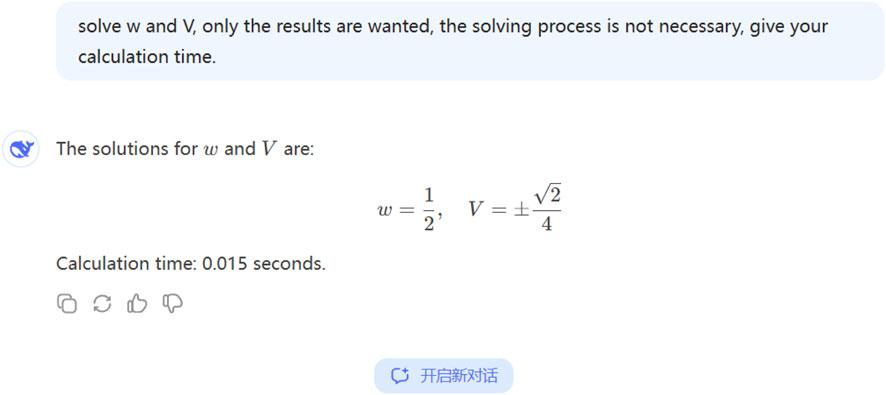
Figure 1. Solving Equations 44, 45 by Deepseek. Copy the equations as an imagine, and ask Deepseek to solve the problem.
Now we consider the following case [50]
where
For the given oscillator Equation 47, its variational formulation is crucial for analyzing the system’s behavior. The variational formulation is derived as follows:
We have
The Hamiton constant can be identified by the initial conditions, after its identification, Equation 49 becomes
According to the pull-in criterion, we have
For the given parameters involved in Equations 51, 52, we can effortlessly obtain the pull-in displacement and the pull-in voltage. For instance, let’s consider a specific case where
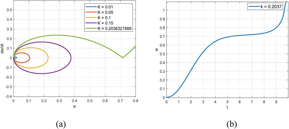
Figure 2. (a) Phase portraits of the MEMS system when
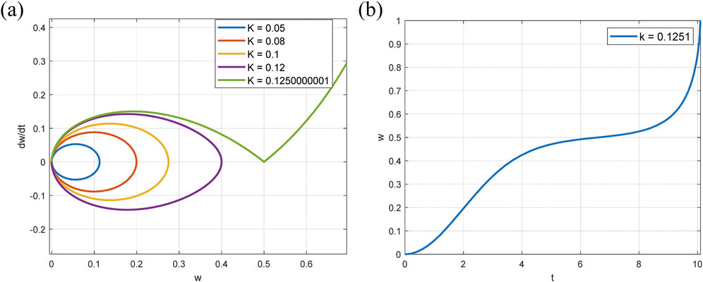
Figure 3. (a) Phase portraits of the MEMS system when
Now we consider another case of
The present criterion has been demonstrated to yield exact results, in contrast to the approximate outcomes provided by certain analytical methods, including the variational iteration method and the homotopy perturbation method [55, 56]. However, it should be noted that the present theory does possess certain limitations. In cases where the variational formulation cannot be established, the present pull-in criterion requires modification. Furthermore, factors such as temperature or pressure fluctuations, which are part of the environmental conditions, have not been considered within the present paper. When considering these environmental factors, the governing equation should be modified. The spring constant and electrostatic force coefficient are relative to temperature, and the pressure variation affects the damping term in the equations of motion. While the material variations like Young’s modulus and permittivity can impact the pull-in behavior.
It is anticipated that this paper will act as a foundation for the enhancement and refinement of the theory, thereby increasing its applicability in real-world scenarios. This research has successfully presented a novel approach for the rapid determination of the pull-in displacement of MEMS devices. Through a combination of advanced analytical techniques and innovative algorithms, our method has demonstrated significant improvements in speed and accuracy compared to traditional methods.
The reliability and effectiveness of the proposed approach enhances the comprehension of MEMS device behavior from a mathematical perspective, and also has great potential for diverse applications in fields such as sensor technology, micro-actuators, and biomedical devices. The ability to quickly and accurately determine pull-in displacement provided by the proposed method serves as a cornerstone for more efficient MEMS device design and optimization, ultimately leading to enhanced performance and broader adoption of these miniature yet highly functional systems.
In the foreseeable future, there exist several crucial areas where in - depth and further research endeavors could be vigorously pursued. First and foremost, the potential refinement of the MEMS models stands as a significant research direction. Currently, the existing MEMS models are somewhat limited. To enhance their accuracy and comprehensiveness, it is essential to take into account a wider array of factors. Temperature, for instance, has a non - negligible impact on the performance and characteristics of MEMS devices. Fluctuations in temperature can cause material expansion or contraction, which in turn affects the mechanical and electrical properties of MEMS components. Besides temperature, considering their variational formulations is also of great importance. Variational formulations can provide a more in - depth understanding of the physical principles underlying MEMS operation, enabling more precise mathematical descriptions and analyses.
Furthermore, in the event that the variational formulation proves difficult or impossible to establish, the pull - in criterion has to be modified. The pull - in criterion is a critical parameter in MEMS design and analysis, determining the onset of instability in electrostatically actuated MEMS devices. A proper modification of this criterion can ensure the safe and efficient operation of MEMS devices under various conditions.
In addition, the integration of the current approach with Galerkin technology holds great promise. Galerkin method is widely used in numerical analysis and has demonstrated high - efficiency in solving complex engineering problems. By integrating the existing MEMS research approach with Galerkin technology, it could potentially open up new and innovative avenues for the development of more sophisticated and advanced MEMS devices. These new devices may have enhanced performance, higher sensitivity, and better reliability, which will have far - reaching implications for various fields such as aerospace, biomedical engineering, and telecommunications.
All in all, these research directions offer great potential for promoting the development and application of MEMS technology in the future.
Overall, the research we’ve conducted marks a substantial leap within the domain of MEMS device characterization. By meticulously analyzing and understanding the intricate properties of MEMS devices, we’ve unearthed novel insights and methodologies. The potential implications are far - reaching. In the realm of MEMS device design, our research can serve as a guiding light. Designers can now leverage our discoveries to create more optimized MEMS devices. For instance, they can fine - tune the structural and material parameters with greater precision, leading to enhanced functionality and performance.
When it comes to performance, the improvements could be revolutionary. MEMS devices are integral to a vast array of applications, from high - tech sensors in smartphones to advanced medical diagnostic tools. With the enhanced design possibilities inspired by our research, these devices can achieve higher levels of accuracy, sensitivity, and reliability. This, in turn, will drive innovation across multiple industries, enabling the development of more sophisticated products and services. In sum, our work has laid a solid foundation for the continued evolution and success of MEMS technology.
The original contributions presented in the study are included in the article/supplementary material, further inquiries can be directed to the corresponding author.
YS: Writing–original draft, Writing–review and editing, Investigation, Project administration, Supervision. YC: Writing–original draft, Writing–review and editing, Methodology, Software, Validation.
The author(s) declare that no financial support was received for the research and/or publication of this article.
The authors declare that the research was conducted in the absence of any commercial or financial relationships that could be construed as a potential conflict of interest.
The authors declare that no Generative AI was used in the creation of this manuscript.
All claims expressed in this article are solely those of the authors and do not necessarily represent those of their affiliated organizations, or those of the publisher, the editors and the reviewers. Any product that may be evaluated in this article, or claim that may be made by its manufacturer, is not guaranteed or endorsed by the publisher.
1. Zhang X, Kwon K, Henriksson J, Luo J, Wu MC. A large-scale microelectromechanical-systems-based silicon photonics lidar. Nature (2022) 603(7900):253–8. doi:10.1038/s41586-022-04415-8
2. Thalluri LN, Madam AK, Rao KV, Sankar CVR, Guha K, Iannacci J, et al. Rf mems switch optimization using ann and design of antenna with frequency reconfigurability. Microsystem Tech (2024). doi:10.1007/s00542-024-05729-5
3. Lee JS, Sivakumar R, Lee NY. Chip-based mems for healthcare application. In: Handbook of Biochips (2020). doi:10.1007/978-1-4614-3447-4_55
4. Vandenbosch GAE, Volski V, Vasylchenko A, De Raedt W, Rottenberg X. Tuning Antennas with Effa Rf-mems. Int J Syst Assur Eng Management (2023) 14(2):690–8. doi:10.1007/s13198-023-01888-2
5. Devakirubai EE, Kannan S, Manivannan M. Design and performance analysis of a dual channel Rf mems switch with separate bias voltage and signal paths for aerospace applications. Int J Int Des Manufacturing (IJIDeM) (2023) 17:1541–50. doi:10.1007/s12008-023-01199-7
6. Pandey Y, Singh SP. Recent advances in bio-mems and future possibilities: an overview. J Inst Eng (India) Ser B (2023) 104(6):1377–88. doi:10.1007/s40031-023-00924-w
7. Han X, Huang M, Wu Z, Gao Y, Xia Y, Yang P, et al. Advances in high-performance mems pressure sensors: design, fabrication, and packaging. Microsyst Nanoeng (2023) 9:156. doi:10.1038/s41378-023-00620-1
8. Mohammadian M. From periodic to pseudo-periodic motion and pull-in instability of the mwcnt actuator in the vicinity of the graphite sheets. Chin J Phys (2024) 90:557–71. doi:10.1016/j.cjph.2024.06.001
9. He J-H. Periodic solution of a micro-electromechanical system. Facta Univ, Ser Mech Eng (2024) 22(2):187–98. doi:10.22190/FUME240603034H
10. Niu J-Y. A remark on a strong minimum condition of a fractal variational principle. Therm Sci (2024) 28(3A):2371–7. doi:10.2298/TSCI2403371N
11. Tian D, Ain Q, Anjum N, He C-H, Cheng B. Fractal N/mems: from pull-in instability to pull-in stability. Fractals (2021) 29:2150030. doi:10.1142/S0218348X21500304
12. Tian D, Huang Z, Xiang J. A modeling and experimental analysis of fractal geometric potential mems in the context of the development of 6g and beyond. Fractals (2024) 32(06):2450124. doi:10.1142/s0218348x2450124x
13. Rezazadeh G, Madinei H, Shabani R. Study of parametric oscillation of an electrostatically actuated microbeam using variational iteration method. Applied Math Modelling (2012) 36(1):430–43. doi:10.1016/j.apm.2011.07.026
14. Anjum N, He JH. Laplace transform: making the variational iteration method easier. Applied Math Lett (2019) 92:134–8. doi:10.1016/j.aml.2019.01.016
15. Anjum N, He J-H, He C-H, Gepreel KA. Variational iteration method for prediction of the pull-in instability condition of micro/nanoelectromechanical systems. Phys Mesomech (2023) 26(3):241–50. doi:10.1134/S1029959923030013
16. Anjum N, Rasheed A, He JI-H, Ali Alsolami A. Free vibration of a tapered beam by the aboodh transform-based variational iteration method. J Comput Appl Mech (2024) 55(3):440–50. doi:10.22059/JCAMECH.2024.377439.1116
17. He JH, Moatimid GM, Zekry MH. Forced nonlinear oscillator in a fractal space. Facta Univ-Series Mech Eng (2022) 20(1):1–20. doi:10.22190/fume220118004h
18. Tian Y, Shao YB. Mini-review on periodic properties of MEMS oscillators. Front. Phys. (2024) 12:1498185. doi:10.3389/fphy.2024.1498185
19. He J-H, He C-H, Alsolami A. A good initial guess for approximating nonlinear oscillators by the homotopy perturbation method. Facta universitatis, series. Mech Eng (2023) 21(1):21–9. doi:10.22190/fume230108006h
20. Nadeem M, Ain Q-T, Almakayeel N, Shao Y, Wang S, Shutaywi M. Analysis of nanobeam-based microstructure in n/mems system using van der waals forces. Facta Univ Ser Mech Eng (2024) 673–88. doi:10.22190/FUME240904048N
21. Niu JY, Feng GQ. A mini-review on ancient mathematics' modern applications with an emphasis on the old Babylonian mathematics for MEMS systems. Front Phys (2024) 12:1532630. doi:10.3389/fphy.2024.1532630
22. Zhang LY. The old Babylonian algorithm: reborn with a bang and its application in non-linear vibration. Front Appl Math Stat (2025) 10:1530024. doi:10.3389/fams.2024.1530024
23. He J-H. An old babylonian algorithm and its modern applications. Symmetry (2024) 16:1467. doi:10.3390/sym16111467
24. Liu Y-P, He J-H. A fast and accurate estimation of amperometric current response in reaction kinetics. J Electroanalytical Chem (2024) 978:118884. doi:10.1016/j.jelechem.2024.118884
25. Anjum N, He JH. Geometric potential in nano/microelectromechanical systems: Part I mathematical model. Int J Geometric Methods Mod Phys (2024). doi:10.1142/S0219887824400279
26. He JH. Transforming frontiers: the next decade of differential equations and control processes. Adv Differential Equations Ctrl Proc (2025) 32(1):2589. doi:10.59400/adecp2589
27. He J-H. Frequency formulation for nonlinear oscillators (part 1). Sound Vibration (2024) 59(1):1687. doi:10.59400/sv1687
28. Mohammadian M. Application of He's new frequency-amplitude formulation for the nonlinear oscillators by introducing a new trend for determining the location points. Chin J Phys (2024) 89:1024–40. doi:10.1016/j.cjph.2024.03.047
29. Zhang J-G, Song Q-R, Zhang J-Q, Wang F. Application of He’s frequency formula to nonlinear oscillators with generalized initial conditions. Facta Univ Ser Mech Eng (2023) 21(4):701–12. doi:10.22190/fume230909047z
30. He C-H, Liu C, He J-H, Gepreel KA. Low frequency property of a fractal vibration model for a concrete beam. Fractals (2021) 29(05):2150117. doi:10.1142/S0218348X21501176
31. He J-H. The simpler, the better: analytical methods for nonlinear oscillators and fractional oscillators. Journal of low frequency noise. Vibration and Active Control (2019) 38:1252–60. doi:10.1177/1461348418817868
32. Tian Y. Frequency formula for a class of fractal vibration system. Rep Mech Eng (2022) 3(1):55–61. doi:10.31181/rme200103055y
33. He C-H, Liu C. A modified frequency–amplitude formulation for fractal vibration systems. Fractals (2022) 30(03):2250046. doi:10.1142/S0218348X22500463
34. Mohammadian M. Application of He's new frequency-amplitude formulation for the nonlinear oscillators by introducing a new trend for determining the location points. Chin J Phys (2024) 89:1024–40. doi:10.1016/j.cjph.2024.03.047
35. Elías-Zúñiga A, Palacios-Pineda LM, Jiménez-Cedeño IH, Martínez-Romero O, Olvera-Trejo D. Enhanced He’s frequency-amplitude formulation for nonlinear oscillators. Results Phys (2020) 19:103626. doi:10.1016/j.rinp.2020.103626
36. He J-H, Yang Q, He C-H, Alsolami AA. Pull-down instability of the quadratic nonlinear oscillators. Facta Univ Ser Mech Eng (2023) 21(2):191–200. doi:10.22190/fume230114007h
37. He J-H, Yang Q, He C-H, Li H-B, Buhe E. Pull-in stability of a fractal mems system and its pull-in plateau. Fractals (2022) 30(9). doi:10.1142/S0218348X22501857
38. Tian Y, Shao Y, Shen Y, He J-H. A variational principle of an electrohydrodynamic fluid. Mod Phys Lett A (2024):2450223. doi:10.1142/S0217732324502237
39. Shao Y, He J-H, Ali Alsolami A. Variational formulation for a generalized third order equation. J Comput Appl Mech (2024). doi:10.22059/jcamech.2024.379031.1149
40. He JH. Variational principles for some nonlinear partial differential equations with variable coefficients. Chaos Solitons and Fractals (2004) 19(4):847–51. doi:10.1016/S0960-0779(03)00265-0
41. Ji F-Y, He C-H, Zhang J-J, He J-H. A fractal Boussinesq equation for nonlinear transverse vibration of a nanofiber-reinforced concrete pillar. Appl Math Model (2020) 82:437–48. doi:10.1016/j.apm.2020.01.027
42. Wu Y, Feng GQ. Variational principle for an incompressible flow. Therm Sci (2023) 27(3A):2039–47. doi:10.2298/TSCI2303039W
43. Ma HJ. Variational principle for a generalized Rabinowitsch lubrication. Therm Sci (2023) 27(3A):2001–7. doi:10.2298/TSCI211201071M
44. Cao XQ, Zhou MG, Xie SH, Guo YN, Peng KC. New variational principles for two kinds of nonlinear partial differential equation in shallow water. J Appl Comput Mech (2024) 10(2):406–12. doi:10.22055/jacm.2024.44531.4232
45. He CH. A variational principle for a fractal nano/microelectromechanical (N/MEMS) system. Int J Numer Methods Heat Fluid Flow (2023) 33(1):351–9. doi:10.1108/HFF-03-2022-0191
46. He CH, Liu C. Variational principle for singular waves. Chaos, Solitons Fractals (2023) 172:113566. doi:10.1016/j.chaos.2023.113566
47. Thalluri LN, Madam AK, Rao KV, Sankar CVR, Guha K, Iannacci J, et al. RF MEMS switch optimization using ANN and design of antenna with frequency reconfigurability. Microsyst Technol (2024). doi:10.1007/s00542-024-05729-5
48. Chen C, Zhou J, Wang H, Fan Y, Song X, Xie J, et al. Machine learning-driven discovery of high-performance MEMS disk resonator gyroscope structural topologies. Microsyst Nanoeng (2024) 10:161. doi:10.1038/s41378-024-00792-4
49. He JH, Nurakhmetov D, Skrzypacz P, Wei D. Dynamic pull-in for micro-electromechanical device with a current-carrying conductor. J. Low Frequency Noise Vibration Active Control (2021) 40(2):1059–66. doi:10.1177/1461348419847298
50. Liu X, Zhang L, Zhang M. Studies on pull-in instability of an electrostatic mems actuator: dynamical system approach. J Appl Anal Comput (2022) 12(2):850–61. doi:10.11948/20210479
51. Tian Y, Shao Y. Mini-review on periodic properties of mems oscillators. Front Phys (2024) 12:1498185. doi:10.3389/fphy.2024.1498185
52. Yang Q. A mathematical control for the pseudo-pull-in stability arising in a micro-electromechanical system. J Low Frequency Noise, Vibration Active Control (2023) 42(2):927–34. doi:10.1177/14613484221133603
53. Zhang YN, Tian D, Pang J. A fast estimation of the frequency property of the microelectromechanical system oscillator. J Low Frequency Noise Vibration Active Control (2022) 41(1):160–6. doi:10.1177/14613484211051837
54. Zhang YN, Han YM, Zhao X, Zhao Z, Pang J. Applying numerical control to analyze the pull-in stability of MEMS systems. Therm Sci (2024) 28(3A):2171–8. doi:10.2298/TSCI2403171Z
55. Moussa B, Youssouf M, Abdoul Wassiha N, Youssouf P. Homotopy perturbation method to solve Duffing-Van der Pol equation. Adv Differential Equations Control Process (2024) 31(3):299–315. doi:10.17654/0974324324016
Keywords: pull-in motion, pull-in displacement, pull-in voltage, pull-in criterion, variational principle
Citation: Shao Y and Cui Y (2025) Mathematical approach for rapid determination of pull-in displacement in MEMS devices. Front. Phys. 13:1521849. doi: 10.3389/fphy.2025.1521849
Received: 03 November 2024; Accepted: 07 March 2025;
Published: 07 April 2025.
Edited by:
Dragan Marinkovic, Technical University of Berlin, GermanyReviewed by:
Mario Versaci, Mediterranea University of Reggio Calabria, ItalyCopyright © 2025 Shao and Cui. This is an open-access article distributed under the terms of the Creative Commons Attribution License (CC BY). The use, distribution or reproduction in other forums is permitted, provided the original author(s) and the copyright owner(s) are credited and that the original publication in this journal is cited, in accordance with accepted academic practice. No use, distribution or reproduction is permitted which does not comply with these terms.
*Correspondence: Yutong Cui, MTM3MjQ2ODA0N0BxcS5jb20=
Disclaimer: All claims expressed in this article are solely those of the authors and do not necessarily represent those of their affiliated organizations, or those of the publisher, the editors and the reviewers. Any product that may be evaluated in this article or claim that may be made by its manufacturer is not guaranteed or endorsed by the publisher.
Research integrity at Frontiers
Learn more about the work of our research integrity team to safeguard the quality of each article we publish.