 Hai-Xin Zhang1†Ya-Chong Hou1†
 Yun-Fei Li1,2*Yun-Fei Yang1
 Kai Li1Jian-Feng Yue1Meng-Yu Jia1Yi-Ting Han3
 Yu Yu1,2*
 Gong Wang1,2Shu-Ping Hou3*
 Yu-Lei Wang1,2Zhi-Wei Lu1,2
- 1Center for Advanced Laser Technology, Hebei University of Technology, Tianjin, China
- 2Hebei Key Laboratory of Advanced Laser Technology and Equipment, Tianjin, China
- 3School of Information Engineering, Tianjin University of Commerce, Tianjin, China
The aerospace sector requires materials, particularly aluminum all, to possess advanced mechanical properties for aircraft skins. Consequently, the industry implements protective coatings to counteract erosion and abrasion. Yet, as time progresses, these coatings can degrade, prompting careful paint removal to extend the longevity of aircraft. This research investigates methods to improve laser cleaning efficiency while safeguarding paint quality. It utilizes a nanosecond pulsed laser to assess factors such as laser energy, cleaning angle, and out-of-focus volume on cleaning efficacy. The findings demonstrate that the optimal energy for cleaning is 20 mJ; exceeding this threshold results in damage to the substrate. Additionally, the cleaning angle significantly impacts efficiency, with an 11° angle yielding the highest effectiveness. Manipulating the laser’s focal point also alters cleaning quality, with 30 mm providing the best outcomes. Single-point laser cleaning tests examined energy levels and cleaning cycles, highlighting that increased energy and cycles lead to surface damage and greater roughness. Furthermore, paint color affected cleaning performance, with blue paint exhibiting superior cleaning effectiveness. This study advances the development of laser cleaning methods for aircraft skins, catering to industry needs for efficient, environmentally friendly maintenance practices.
1 Introduction
In recent years, the aerospace sector has increasingly prioritized the improvement of the mechanical characteristics of materials utilized in aircraft manufacturing [1]. Aluminum alloy is particularly distinguished by its strength that rivals alloy steel. Its remarkable properties include excellent casting ability, along with impressive thermal and electrical conductivity. These features render it a favored material for aircraft skins [2]. These aircraft surfaces face vulnerability to erosion and abrasion in intricate environments. To address these issues, a tailored protective coating is carefully applied to aluminum alloy surfaces, shielding them from external factors. This coating not only prevents corrosion and wear but also enhances aesthetic appeal [3]. Common coating types encompassing alkyd, acrylic, epoxy, polyurethane, and fluorocarbon formulations were reported [4–6]. Over time, however, these aircraft skin undergoes aging, leading to issues like cracks, partial detachment, and other concerns arising from exposure to light, temperature, humidity, and reactive anions. Regular evaluation of delicate sensing components and skin junctions beneath the aircraft envelope is essential. This requires meticulous stripping of paint from the aircraft surface [7, 8].
Traditional cleaning methods such as sandblasting, chemical solvents, ultrasonic treatment, and high-pressure water jets have been used for this purpose. However, these methods are burdened with labor intensiveness, high energy consumption, and environmental pollution [9–12]. As a result, there is a compelling need to develop an aircraft skin cleaning technology that is environmentally sustainable and cost-effective. Laser cleaning technology, utilizing high-energy lasers to irradiate surfaces, triggers physical and chemical reactions in the contaminant layer. This leads to processes like combustion, expansion, vaporization, and volatilization of pollutants, effectively achieving the cleansing objective [13–15]. Laser cleaning offers advantages such as environmental friendliness, non-contact operation, high precision, and efficacy [16, 17]. It has been touted as “the new cleaning technology with the greatest potential in the 21st century” and is widely adopted for removing paint layers from aircraft skins [18].
The exploration of laser cleaning began in 1965 when Schawlow [19] employed lasers to remove impurities from historical artifacts. Subsequently, Bedair introduced the concept of using lasers to clean metal surfaces containing sulfides. With the proliferation of laser machine types and deeper research into cleaning mechanisms, laser technology has gained substantial traction in the industrial realm. In 2018, Zhang et al. [20] utilized a quasi-continuous fiber laser to quantitatively remove lacquer layers from aluminum substrates, revealing a link between coating thickness and cleaning effectiveness. In 2020, Liu et al. [21] studied laser ablation of polyurethane-painted hull plates, investigating the impact of cleaning durations on paint layer removal. Shan et al. [22] used a nanosecond pulsed fiber laser to remove paint from 2024 aluminum alloy surfaces, achieving effective cleaning while preserving surface integrity. Kim et al. [23] employed a low-power Q-switched fiber laser to eliminate primer and oxide layers from steel surfaces for shipbuilding, determining optimal parameters for efficient pretreatment. In 2022, Ren et al. [24] employed Nd:YAG pulsed solid-state lasers to meticulously clean aerospace-grade magnesium-aluminum alloys, exploring cleaning effects under varied laser energy densities. Zhang et al. [25] focused on laser cleaning of blue PU paint layers on magnesium-aluminum alloy substrates, utilizing a nanosecond pulsed fiber laser to delve into primary cleaning mechanisms during the process.
Assessment of laser cleaning effectiveness primarily centers on changes in surface roughness and microscopic morphology following the cleaning process. This study scrutinizes how laser energy, defocusing volume, and cleaning angle influence final cleaning outcomes. Utilizing a nanosecond pulsed laser at 200 Hz, extensive area-based laser cleaning experiments were conducted on aircraft skins, initially applying the control variable method. To mitigate heat accumulation, high-energy nanosecond pulsed lasers at 1 Hz were employed for focused point cleaning. This investigation explores the effects of energy dosage, cleaning cycles, and paint hue on cleaning results. The quality assessment encompasses visual observation and meticulous microscopic analysis. The experimental findings contribute to the advancement of laser-based cleaning in this domain.
2 Experimental procedure
2.1 Experimental investigation of area laser cleaning
The experimental substrate material used is the 2024 aluminum alloy, known for its advantages of high hardness, good heat resistance, and easy processing, making it widely used in the aerospace field. This paper employs a solid nanosecond pulsed laser independently developed by our team for laser cleaning experiments. The process of laser cleaning is illustrated in Figure 1 below. After the laser output from the device, the laser is directed vertically onto a mirror. Following reflection and oscillation within the mirror, the laser emission changes from a “point” to a controlled “line” lengthwise, which is then irradiated onto the surface of the designated sample for cleaning. Through precise control of the platform’s movement, large-area cleaning of the aircraft skin is ultimately achieved. The specific laser parameters are detailed in Table 1 below.
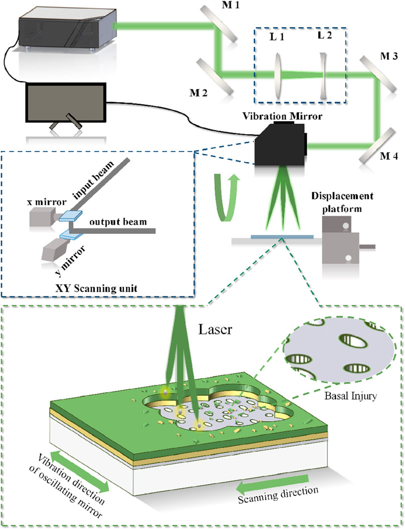
Figure 1. Schematic diagram of regional laser cleaning experiment.
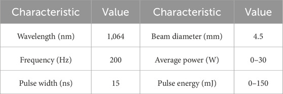
Table 1. Regional laser cleaning experiment related parameters.
The vibration mirror comprises an X-axis reflector and a Y-axis reflector, both propelled by a motor, facilitating controlled movement. The manipulation of glass rotation allows for modulation of beam deflection. In the experiment, it is controlled by an external signal generator, which can achieve adjustable vibration frequency, amplitude size, and input signal type. The relevant parameters of the vibration mirror are shown in Table 2 below.
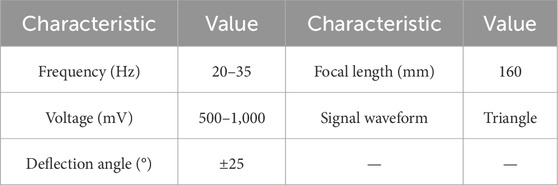
Table 2. Parameters related to laser scanning oscillator.
During the experiment, the horizontal displacement speed of the numerical control platform is always 1 cm/s; by controlling the magnitude of the input current, five sets of data with laser energy of 5, 10, 15, 20, and 25 mJ were selected for analysis, study the effect of power on the impact of cleaning.
Typically, laser cleaning experiments are conducted at a 90° angle of incidence to the material surface for cleaning. However, in the actual application process, the cleaning angle will change due to the irregular surface of the Aircraft skins, resulting in distortion of the laser spot on the skin’s surface.
A distinct relationship exists between the deflection angle and the laser spot area. When the laser beam with a focused diameter of d is deflected at an angle of θ, the irradiated spot area S′ on the material surface can be mathematically expressed as follows (as shown in Equation 1):
Therefore, this experiment by adjusting the spot deflection distance and selected deflection angles of 0°, 6°, 11°, 16° and 21° of the five groups of data for analysis to study the effect of cleaning angle on the laser cleaning effect.
Furthermore, during laser cleaning operations, maintaining the laser’s focal point consistently within the cleaning plane poses a challenge. This discrepancy can induce variations in cleaning efficacy and result in the phenomenon of defocusing. Moreover, because the positive and negative defocusing in the cleaning effect and mechanism are identical, so this experiment by adjusting the position of the platform so that the negative defocusing distance to 0 cm, 30 mm, 60 mm, 90 mm, and 120 mm, respectively, to analyze the results of the five groups of experiments to study the impact of the amount of defocusing on the quality of laser cleaning.
2.2 Experimental study of single-point laser cleaning
The laboratory’s internally developed laser cleaning apparatus encompasses a high-energy nanosecond pulsed laser, a numerical control platform, display, water cooling system, and power supply. The primary objective of this experiment is to mitigate the phenomenon of thermal accumulation and investigate the impact of a single-pulse laser on the laser cleaning efficacy. Consequently, the scanning oscillator system is discontinued, enabling the high-energy laser to directly interact with the material surface for cleaning purposes. The optical configuration of the core equipment, the nanosecond pulsed laser, is illustrated in Figure 2 below.
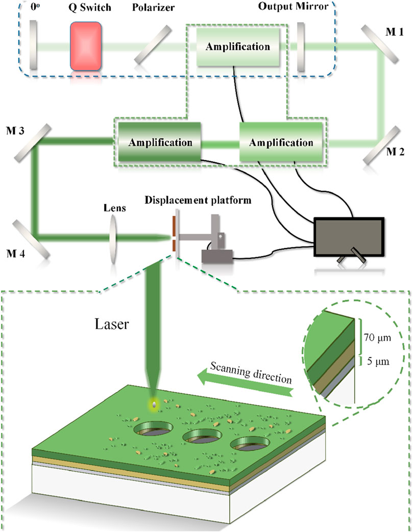
Figure 2. Schematic diagram of single-point laser cleaning experiment.
The primary components encompass: 45° reflectors denoted as M1, M2, M3, and M4; a 0° reflector designated as M5; an output mirror denoted as M6; polarizer P1; focusing lens L1; the Q switch and amplifiers A1, A2, and A3. The resonant cavity R1 facilitates oscillation and amplification of the initial seed laser. The laser output undergoes reflection by reflectors M1 and M2, subsequently traversing amplifiers A2 and A3 for sequential magnification. The amplified laser then passes through reflectors M3 and M4, followed by focal adjustment through the focusing lens, ultimately impinging upon the material surface to execute single-pulse laser cleaning experiments. Pertinent experimental parameters are itemized in Table 3 below.
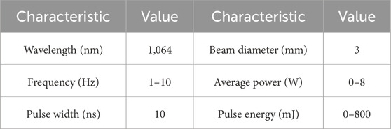
Table 3. Single-point laser cleaning experiment-related parameters.
Within this experimental framework, manipulation of the laser’s repetition frequency and input current enabled the generation of two distinct sets of experimental data. These datasets corresponded to cleaning cycles ranging from 1 to 5, while the single-pulse energy spanned from 0 to 0.67 J. The ensuing analysis focused on investigating the influence of cleaning frequency and energy dosage on cleaning efficacy, and the impact of paint color on the paint removal effect was also discussed.
3 Results and discussion
3.1 Experiments on laser cleaning of surfaces
3.1.1 The impact of laser energy on cleaning quality
The peak power densities were 4.72, 9.43, 14.15, 18.87, and 23.58 MW/mm2 for the experimental single pulse energy range of 5 mJ–25 mJ, while the cleaning effect became more and more prominent, as shown in Figure 3 below.
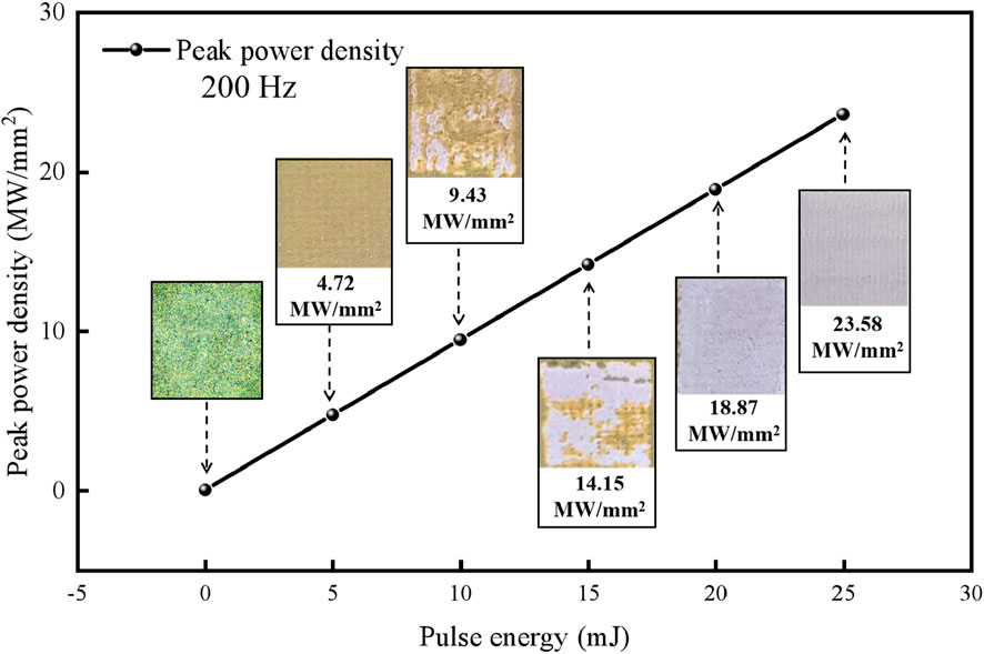
Figure 3. Schematic diagram of the effect of energy on peak power density and laser cleaning effect.
When the single pulse energy reaches 10 mJ, it can be seen that part of the yellow primer has been completely removed, and the white substrate begins to appear, indicating that the cleaning threshold of the paint layer has been reached at this time, which is 9.43 MW/mm2; Upon scaling the single pulse energy to 20 mJ, an entire surface paint layer of the aircraft skin can be effectively and wholly removed, manifesting an optimal cleaning outcome bereft of observable impairments. However, as the laser energy escalates to 25 mJ, the cleaning domain begins to manifest evident instances of pinpoint and streak-based damage. This outcome stems from the peak power density surpassing the threshold for laser cleaning-induced impairment.
A confocal microscope was employed to scrutinize the post-cleaning surface, with the outcomes presented in Figure 4A below. Upon using a single pulse energy of 5 mJ, the cleansed paint layer surface manifested a densely distributed, furrow-like configuration. No accumulation of molten residue was evident, leading to a preliminary inference that the expulsion of the paint layer ensued due to the thermal vibrational effect during laser cleaning. At 10 mJ energy, the thermal vibrational impact intensifies, culminating in a marked augmentation of the paint removal area. Upon reaching a single pulse energy of 20 mJ, the cleansed substrate attains an unblemished state. However, at 25 mJ energy, the substrate’s surface starts to exhibit a pitted and structurally compromised aspect.
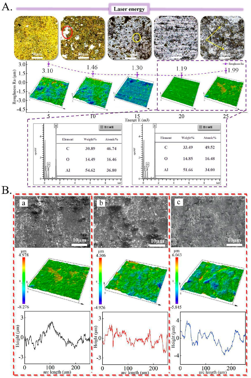
Figure 4. (A) Area laser cleaning microscopic morphology at different energies, (B) Effect of cleaning angle on microscopic morphology of skin.
The surface roughness of the treated substrates measured 3.10, 1.46, 1.30, 1.19 and 1.99 μm at energy levels ranging from 5 mJ to 25 mJ. It is evident that the surface roughness initially diminishes and subsequently escalates with rising laser energy. Notably, the optimal surface roughness is achieved at an energy of 20 mJ. Upon analysing the points corresponding to 20 mJ and 25 mJ regarding carbon elements beneath the surface, it is observed that the carbon element content increased from 46.74% to 49.52%. This augmentation suggests that excessive energy may lead to substrate impairment, thereby diminishing the efficacy of laser cleaning.
3.1.2 Influence of cleaning angle on cleaning quality
The investigation employed scanning electron microscopy and confocal microscopy to scrutinize the microscopic attributes of the laser-treated aluminum alloy surface. The outcomes are presented in Figure 4B below. Figures a–c are aligned with cleaning angles of 0°, 11° and 21°, sequentially. Upon analyzing the microscopic morphologies, it becomes apparent that with an increment in the cleaning angle, a progressively intricate groove-like structure emerges on the substrate’s surface, while the residual paint fragments decrease incrementally. The three-dimensional morphogram highlights that an elevation in the angle contributes to the escalation of the extreme surface height, surging from 4.978 μm to 6.043 μm. This inclination results in the formation of a “ridge” pattern on the surface, with the corresponding three-dimensional profile crest becoming more comprehensive and expanding in range.
The surface’s elemental distribution was acquired through EDS analysis, as illustrated in Figure 5 below. Figures a–c correspond to cleaning angles of 0°, 11°, and 21°, respectively. The analysis revealed that the carbon element content on the surface exhibited a gradual reduction with an augmentation in the cleaning angle. The mass percentage exhibited an 8.75% decline, while the atomic proportion decreased by 9.79%. Conversely, the content of surface oxygen and aluminum elements witnessed an increment. The mass percentages for oxygen and aluminum increased by 3.92% and 4.84%, respectively, while the atomic ratios augmented by 5.3% and 4.49%, correspondingly.
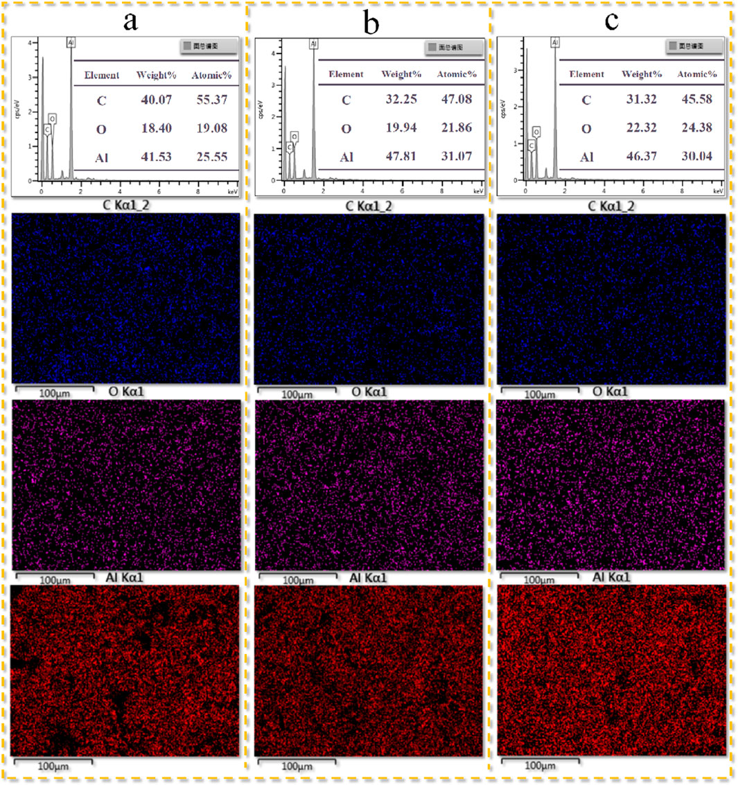
Figure 5. The effect of cleaning angle on the content and distribution of surface elements. (A) Cleaning angle of 0°; (B) Cleaning angle of 11°; (C) Cleaning angle of 21°.
The surface roughness along with the associated microscopic morphology of the cleaned skin under distinct laser angles is depicted in Figure 6A below. Notably, the surface roughness reaches its zenith at a vertical incidence angle, indicating the attainment of the laser cleaning’s damage threshold. As the angle of incidence progressively elevates, the surface roughness tends to diminish initially and then subsequently expand. The extent of substrate deformation becomes more conspicuous, progressively forming a rippled surface structure. Remarkably, when the cleaning angle attains 11°, the surface roughness reaches a nadir of 1.25 μm.
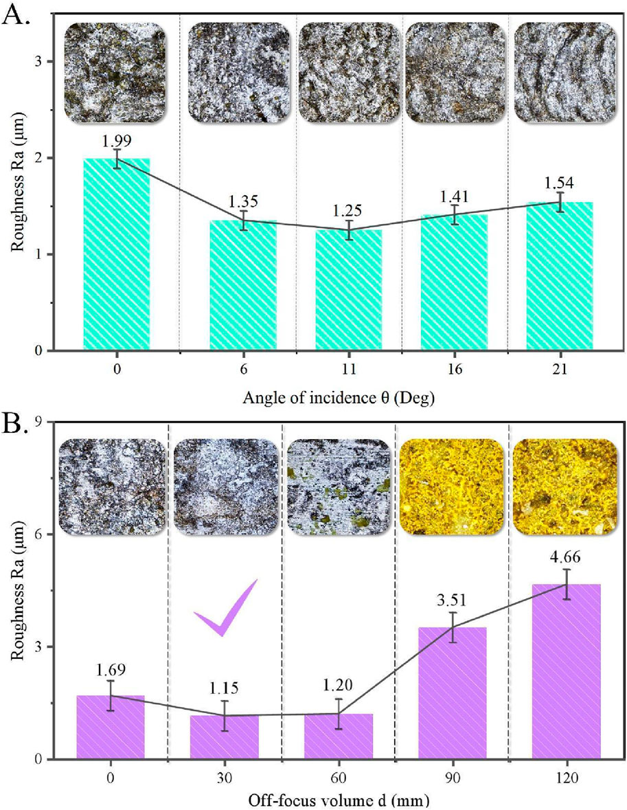
Figure 6. (A) Effect of cleaning angle on the microscopic morphology and roughness of skin surface, (B) Influence of off-focus volume on the microscopic morphology and roughness of skin surface.
3.1.3 Impact of off-focus volume on cleaning quality
Throughout the cleaning process, alterations in the extent of defocusing inherently influence the quality of cleaning outcomes. Employing a confocal microscope, the microscopic surface was meticulously examined, and the outcomes are graphically depicted in Figure 6B below. Remarkably, microscopic morphology elucidates that with an increment in the degree of defocusing, the attenuation of laser peak power density undergoes a progressive amplification. Consequently, this engenders an incremental buildup of residual paint layers upon the surface, leading to a deterioration in the efficacy of laser cleaning. Furthermore, at an out-of-focus distance of 30 mm, the surface adopts a planar configuration devoid of groove-like structures, simultaneously achieving a minimal surface roughness of 1.15 μm—a manifestation of optimal laser cleaning efficiency. In stark contrast, as the out-of-focus distance extends to 90 mm, a sudden surge in surface roughness and height disparity is observed, escalating to 3.51 μm and 34.454 μm, respectively. Notably, the emergence of groove-like structures becomes apparent, ultimately culminating in a perceptible degradation of cleaning results.
3.2 Experimental investigation of single-point laser cleaning
This section encompasses single-point laser cleaning experiments on aircraft skins using high-energy lasers. These experiments aim to address thermal accumulation issues associated with laser cleaning, while also independently investigating the influence of cleaning frequency on cleaning effectiveness and exploring the impact of paint color on paint removal efficiency. The findings from these experiments hold significant implications for the further refinement of precise laser cleaning technology. The outcomes of the single-point laser cleaning experiments on aircraft skins are presented in Figure 7 below, with the horizontal axis representing the number of laser cleaning cycles and the vertical axis representing laser pulse energy.
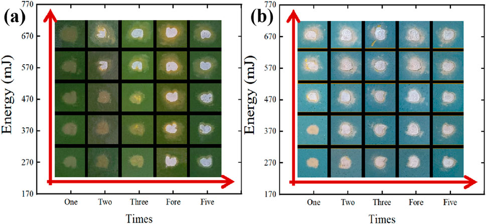
Figure 7. Experimental results of single-point laser cleaning of aircraft skins.
3.2.1 Impact of off-focus volume on cleaning quality
A distinct overlap region occurs between adjacent laser spots, resulting in multiple cleaning interactions on the mask surface within this zone. This phenomenon significantly influences the overall cleaning outcome. While maintaining consistent experimental parameters, the study examines alterations in substrate surface micro-morphology and roughness when subjected to laser cleaning cycles ranging from 1 to 5 times. The outcomes are illustrated in Figure 8A below.
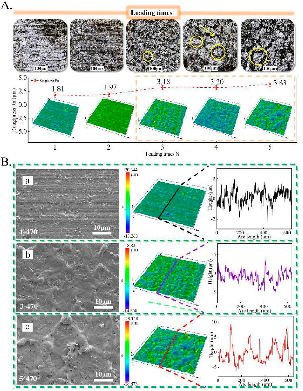
Figure 8. (A) Laser cleaning times on the image of skin microscopic morphology, (B) Effect of the number of laser cleaning on the height profile of the skin surface.
The findings reveal that after a single instance of laser cleaning, the skin’s surface remains free from apparent structural damage, signifying optimal cleaning efficiency. Furthermore, with escalating cleaning repetitions, the diameter of the damaged structures expands, exacerbating the degree of impairment. Across the range of 1–5 cleaning cycles, the associated surface roughness values are 1.81, 1.97, 3.18, 3.20, and 3.83 μm, respectively. This trend underscores that heightened cleaning frequency not only amplifies surface roughness but also intensifies the extent of surface damage.
As depicted in Figure 8B, when the laser energy is set at 470 mJ, a singular laser cleaning operation results in an undisturbed surface with no indications of melted damage; the surface exhibits a sleek appearance. Nonetheless, with a progressive increment in pulse count, the surface’s disparity in height augments from 33.607 μm to 47.001 μm. Notably, following five consecutive cleaning cycles, a heightened presence of melt-induced damage becomes apparent on the skin’s surface, coupled with an emerging trend of substrate detachment.
Laser cleaning was performed for 1, 3, and 5 cycles, with the corresponding surface elemental distribution depicted in Figure 9. It is evident that the carbon element content on the surface exhibits an initial increase followed by a subsequent decline with varying pulse numbers. Notably, in comparison to a single laser cleaning session, the atomic percentage of carbon element reduces by 2.81%, oxygen element by 3.76%, while the atomic percentage of aluminum element increases by 6.59% following five successive cleaning cycles. These outcomes underscore that augmenting the frequency of cleaning sessions can effectively enhance the overall cleaning efficiency.
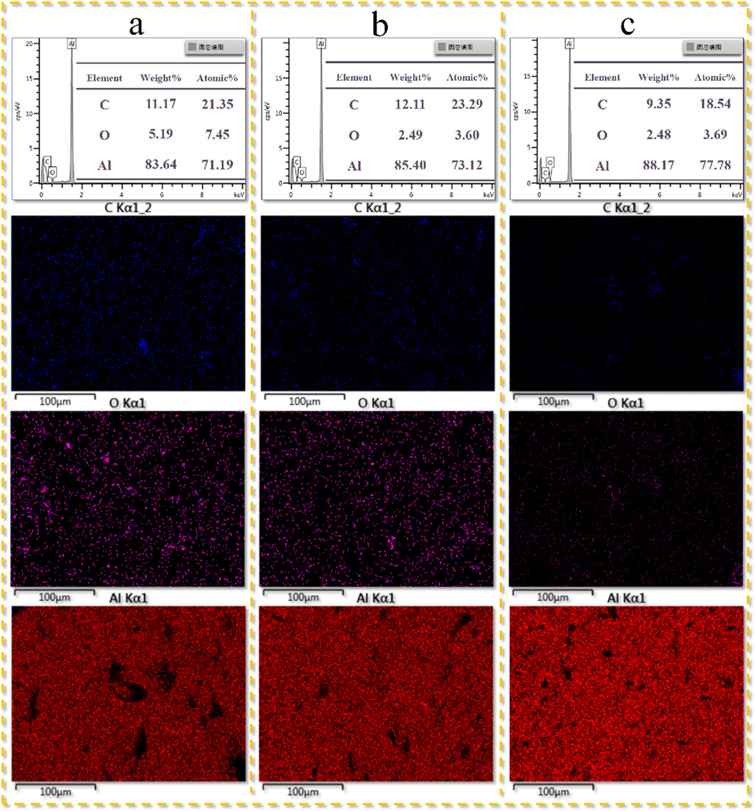
Figure 9. The effect of cleaning times on the content and distribution of surface elements. (A) One cleaning cycle; (B) Three cleaning cycles; (C) Five cleaning cycles.
3.2.2 Influence of pulse energy on cleaning quality
The microscopic morphology of the cleaned surface was examined at single pulse energies of 270, 370, 470, 570, and 670 mJ, as depicted in Figure 10A below.
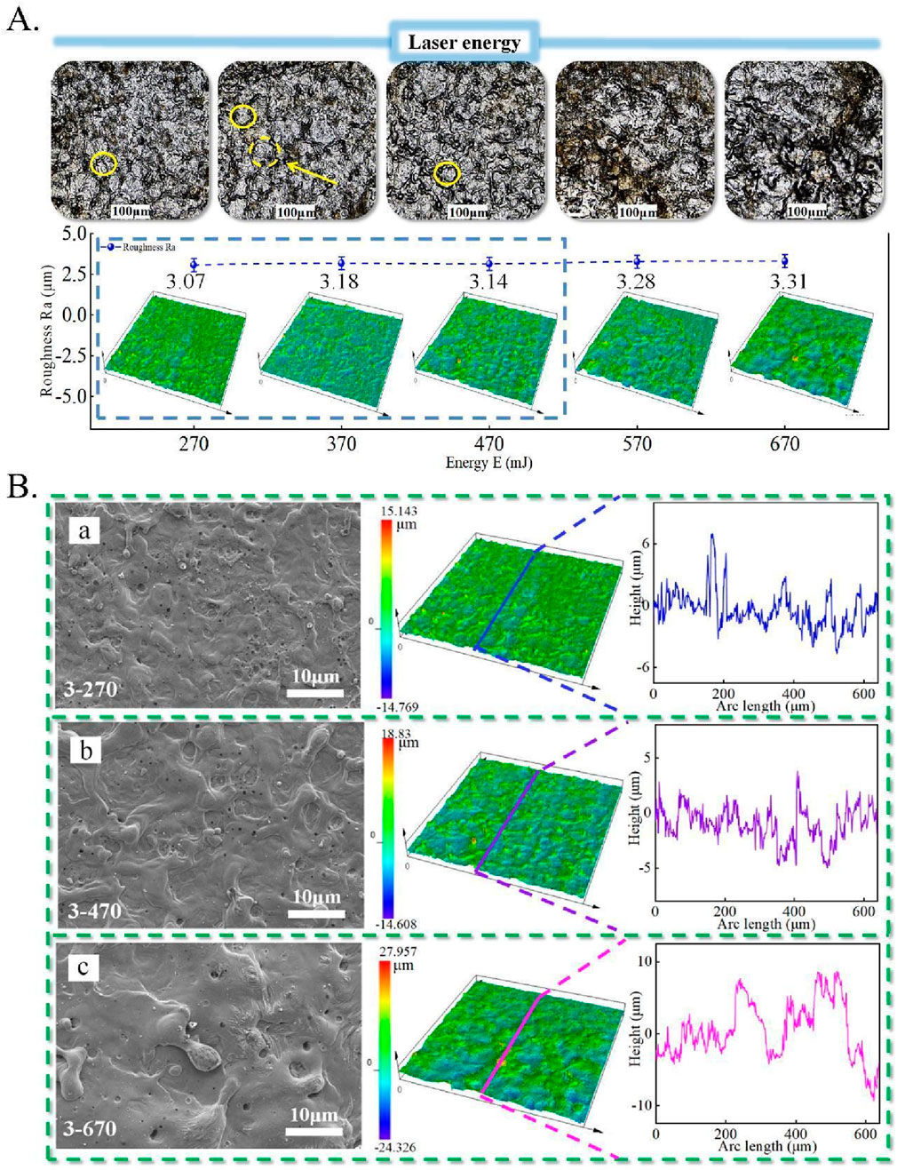
Figure 10. (A) Laser energy on the image of skin microscopic morphology, (B) Effect of laser energy on the height profile of the skin surface.
The investigation revealed that a pulse energy of 270 mJ initiated damage to the skin substrate, manifested as densely distributed, molten-sputtering, crater-like structures. As energy escalated to 570 mJ and 670 mJ, surface damage experienced substantial augmentation, rendering the system chaotic and challenging to discern, with the surface cloaked in black residue. The 3D morphology diagram unveiled a progressive emergence of skin surface damage structures as energy levels rose, concomitant with a gradual increment in surface roughness. Notably, the minimum surface roughness was attained at 270 mJ, measuring 3.07 μm.
In addition, at laser energy levels of 270, 470, and 670 mJ, the surface height differences are 29.912, 33.438, and 52.283 μm, respectively. These results indicate that surface damage experiences a sudden increase once the energy surpasses a specific threshold value, as illustrated in Figure 10B below.
The elemental distribution on the skin’s surface is depicted in Figure 11 below. The observations reveal a slight initial rise followed by a significant decline in surface carbon content as energy levels increase. Simultaneously, the content of elemental oxygen exhibits a gradual reduction, while the content of elemental aluminum experiences a noteworthy escalation. In terms of atomic percentages, a collective decrease of 1.58% and 0.89% is observed for carbon and oxygen elements, respectively, alongside a rise of 2.46% for aluminum elements. These outcomes suggest that elevated energy levels might induce the disruption of the alumina film, thereby exposing the substrate and engendering alterations in surface elemental composition.
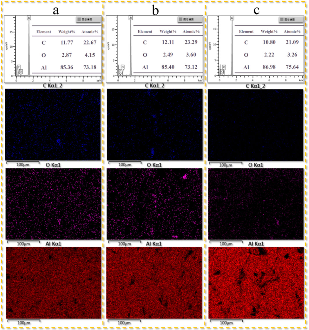
Figure 11. The effect of laser energy on the content and distribution of surface elements. (A) Low energy level; (B) Medium energy level; (C) High energy level.
A comparison of the effects of different cleaning times and energies on the microscopic morphology of the skin surface post-cleaning is presented in Figure 12 below. Keeping other variables constant, graphs (a), (b), and (c) correspond to laser energies of 270, 470, and 670 mJ, respectively, while graphs (d), (e), and (f) represent cleaning times of 1, 3, and 5 times, respectively. The findings indicate that as energy gradually increases, the substrate surface damage structure remains relatively unchanged, yet the heat-affected area due to laser cleaning significantly expands. Therefore, it can be concluded that an increase in the number of cleaning cycles does not notably influence changes in the laser cleaning area, but it does lead to a significant increase in surface damage.
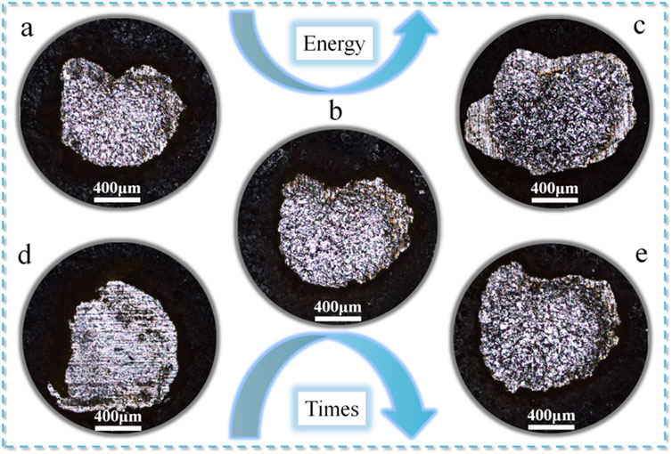
Figure 12. Effect of cleaning times and laser energy on the microscopic morphology of the skin. (A–C): Laser energies of 270 mJ, 470 mJ, and 670 mJ, respectively, with cleaning time held constant. (D–F): Cleaning times of 1, 3, and 5 cycles, respectively, with laser energy held constant.
3.2.3 The influence of paint color on cleaning quality
Laser cleaning experiments were conducted on aircraft skins of different colors using energies ranging from 270 mJ to 670 mJ. The results obtained through confocal microscope observation are presented in Figure 13 below.

Figure 13. Effect of paint color on the microscopic morphology and roughness of the skin surface.
Within the energy range of 270 mJ–470 mJ, complete removal of the surface paint layer from the green aircraft skin was not achieved. Significant paint residues were visible on the cleaned skin’s surface. Thorough cleaning was achieved at an energy level of 570 mJ, while substrate damage occurred at 670 mJ. In contrast, complete surface cleaning was achieved at a laser energy of 270 mJ when cleaning the blue skin. With increasing energy, surface damage gradually escalated. Across laser energies of 270 mJ–670 mJ, the associated surface roughness for green skin cleaning stood at 4.2, 3.65, 3.30, 2.02, and 2.66 μm, respectively. For blue skin cleaning, the corresponding surface roughness values were 3.07, 3.18, 3.14, 3.28, and 3.31 μm. To further comprehend the influence of paint color on cleaning outcomes, subsequent experiments were undertaken.
An infrared grating spectrometer was employed to measure the reflected light. Stronger received reflected light indicates lower absorption capacity of the paint layer towards the laser, while weaker received reflected light signifies stronger absorption capability of the paint layer towards the laser. To ensure the efficiency and precision of the infrared spectrometer acquisition, the laser’s repetition frequency for this experiment was set to 200 Hz, ensuring the detection probe remained consistently positioned for accurate readings.
Twenty laser cleaning experiments were conducted on both green and blue skins, respectively, with the spectrometer probe collecting reflected light waves at the same position. Finally, the spectra depicting absorbed light intensity versus laser wavelength were plotted in Figure 14 below. During the laser cleaning experiment on the green aircraft skin, the reflected laser light intensity reached 10,720 cd. Conversely, in the case of the blue aircraft skin, the reflected light power was only 6,193 cd, highlighting a nearly twofold difference between the two scenarios.
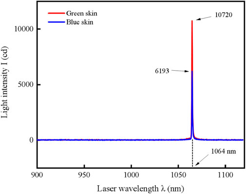
Figure 14. Infrared spectra under different skin colors.
4 Conclusion
In this research, a pair of disparate laser cleaning experiments were devised, employing a low repetition-frequency yet high-energy laser system. The intent was to discern the multifaceted influences of laser energy levels, cleaning angles, repetition frequencies, degrees of defocusing, and the variegation of paint hues upon the minuscule topography of the treated substrate, along with the discernible dispersion of constituent surface elements. The outcomes of this investigative undertaking manifested in the subsequent manner: (1) The escalation of laser energy progressively enhances the efficacy of laser cleaning. At 20 mJ, the threshold for effective cleaning is achieved; however, at 25 mJ, damage to the alumina film leads to substrate melting and increased carbon content on the cleaned surface. Surface roughness peaks at 5 mJ (3.10 μm) and reaches its lowest at 20 mJ (1.19 μm). As the cleaning angle increases from 0° to 21°, the substrate surface exhibits gradual wrinkling. At 0°, the roughness peaks at 1.99 μm, while at 11°, it decreases to a minimum of 1.25 μm, indicating the optimal cleaning effect. However, as the out-of-focus distance grows from 0 cm to 12 cm, the cleaning effect deteriorates progressively. Surface roughness reaches a minimum of 1.15 μm at 3 cm and increases to a maximum of 4.66 μm at 12 cm. Throughout the experiment, no smoke is observed, and the peeled paint layer is mostly fragmented. (2) The experiments revealed that increasing the number of cleaning cycles does not lead to an expansion of the thermal impact zone, but it does intensify substrate damage. Simultaneously, the concentration of carbon elements on the surface gradually accumulates, displaying an initial increase followed by a decline. The roughness reaches a minimum of 1.81 μm after 1 cleaning and a maximum of 3.83 μm after 5 cleanings. In terms of energy variation, the expansion of thermal effects is influenced by energy increase, while the degree of substrate damage remains relatively unchanged. Surface roughness attains a minimum of 3.07 μm at 270 mJ and a maximum of 3.31 μm at 670 mJ. Laser energy absorption varies with paint colors. Particularly, in this experiment, the absorption capacity is more pronounced for the blue paint layer than for the green paint layer.
Data availability statement
The original contributions presented in the study are included in the article/supplementary material, further inquiries can be directed to the corresponding authors.
Author contributions
H-XZ: Writing–original draft, Writing–review and editing. Y-CH: Writing–original draft, Writing–review and editing. Y-FL: Funding acquisition, Investigation, Resources, Supervision, Writing–original draft, Writing–review and editing. Y-FY: Writing–original draft, Writing–review and editing. KL: Supervision, Writing–original draft, Writing–review and editing. J-FY: Writing–original draft, Writing–review and editing. M-YJ: Writing–original draft, Writing–review and editing. Y-TH: Writing–original draft, Writing–review and editing. YY: Funding acquisition, Investigation, Resources, Supervision, Writing–original draft, Writing–review and editing. GW: Funding acquisition, Investigation, Resources, Supervision, Writing–original draft, Writing–review and editing. S-PH: Funding acquisition, Investigation, Resources, Supervision, Writing–original draft, Writing–review and editing. Y-LW: Funding acquisition, Investigation, Resources, Supervision, Writing–original draft, Writing–review and editing. Z-WL: Investigation, Resources, Supervision, Writing–original draft, Writing–review and editing.
Funding
The author(s) declare that financial support was received for the research, authorship, and/or publication of this article. This work was supported by 173 Project Technical Fund (Grant number: 2022-JCJQ-JJ-0416); Central Government Guides Local Funds for Scientific and Technological Development (Grant number: 236Z1813G); Natural Science Foundation of Hebei Province (Grant number: F2023202082, F2022202035); National Natural Science Foundation of China (Grant number: 62075056); Tianjin Key Laboratory of Photoelectric Detection Technology and System (Grant number: 2024LODTS105); Tianjin Science and Technology Project of Special Correspondent (24YDTPJC00780); and Open Project of Hebei Province Key Laboratory of Advanced Laser Technology and Equipment (HBKL-ALTE2024009).
Conflict of interest
The authors declare that the research was conducted in the absence of any commercial or financial relationships that could be construed as a potential conflict of interest.
Generative AI statement
The author(s) declare that no Generative AI was used in the creation of this manuscript.
Publisher’s note
All claims expressed in this article are solely those of the authors and do not necessarily represent those of their affiliated organizations, or those of the publisher, the editors and the reviewers. Any product that may be evaluated in this article, or claim that may be made by its manufacturer, is not guaranteed or endorsed by the publisher.
References
1. Zhang XS, Chen YJ, Hu JL. Recent advances in the development of aerospace materials. Prog Aerospace Sci (2018) 97:22–34. doi:10.1016/j.paerosci.2018.01.001
2. Jiru WG, Sankar MR, Dixit US. Laser surface alloying of copper, manganese, and magnesium with pure aluminum substrate. J Mater Eng Perform (2016) 25(03):1172–81. doi:10.1007/s11665-016-1922-x
3. Deng J, Zhao GR, Lei JH, Zhong L, Lei Z. Research progress and challenges in laser-controlled cleaning of aluminum alloy surfaces. Mater (2022) 15(16):5469. doi:10.3390/ma15165469
4. Kausar A. Corrosion prevention prospects of polymeric nanocomposites: a review. J Plast Film Sheeting (2019) 35(02):181–202. doi:10.1177/8756087918806027
5. Gu HB, Ma C, Gu JW, Guo J, Yan X, Huang J, et al. An overview of multifunctional epoxy nanocomposites. J Mater Chem C (2016) 4(25):5890–906. doi:10.1039/c6tc01210h
6. Zhao HC, Qiao YL, Du X, Wang S, Zhang Q, Zang Y, et al. Laser cleaning performance and mechanism in stripping of Polyacrylate resin paint. Appl Phys A-materials Sci Process (2020) 126(05):360. doi:10.1007/s00339-020-03551-0
7. Shan T, Yin F, Wang S, Qiao Y, Liu P. Surface integrity control of laser cleaning of an aluminum alloy surface paint layer. Appl Opt (2020) 59(30):9313–9. doi:10.1364/AO.404030
8. Morelli U, Dalla Vedova MDL, Maggiore P. Automatic painting and paint removal system: a preliminary design for aircraft applications. Advances in service and industrial robotics. Raad (2018) 67:640–50. doi:10.1007/978-3-030-00232-9_67
9. Yu Z, Dong YJ, Zheng GM, Jiang X, Cheng X, Yang X, et al. Influence of micro sandblasting on the surface integrity of the AlTiN-coated tools. Int J Adv Manufacturing Technol (2022) 120(1-2):1359–72. doi:10.1007/s00170-022-08890-1
10. Gul A, Hruza J, Yalcinkaya F. Fouling and chemical cleaning of microfiltration membranes: a mini-review. Polymers (2021) 13(06):846. doi:10.3390/polym13060846
11. Mat-Shayuti MS, Tuan Ya TMYS, Abdullah MZ, Megat Khamaruddin PNF, Othman NH. Progress in ultrasonic oil-contaminated sand cleaning: a fundamental review. Environ Sci Pollut Res (2019) 26(26):26419–38. doi:10.1007/s11356-019-05954-w
12. Chomka G, Chodor J, Kukielka L, Kasperowicz M. The use of a high-pressure water-ice jet for removing worn paint coating in renovation process. Materials (2022) 15(03):1168. doi:10.3390/ma15031168
13. Sun Q, Zhou JZ, Meng XK, Yang JN, Guo ZH, Zhu M, et al. Mechanism and threshold fluence of nanosecond pulsed laser paint removal. Rare Met (2021) 41(03):1022–31. doi:10.1007/s12598-021-01817-x
14. Zou WF, Xie YM, Xiao X, Zeng XZ, Luo Y. Application of thermal stress model to paint removal by Q-switched Nd:YAG laser. Chin Phys B (2014) 23(07):074205. doi:10.1088/1674-1056/23/7/074205
15. Zhang GX, Hua XM, Huang Y, Zhang Y, Li F, Shen C, et al. Investigation on mechanism of oxide removal and plasma behavior during laser cleaning on aluminum alloy. Appl Surf Sci (2020) 506:144666. doi:10.1016/j.apsusc.2019.144666
16. Kumar A, Prasad M, Bhatt RB, Behere P, Afzal M. Laser shock cleaning of radioactive particulates from glass surface. Opt Lasers Eng (2014) 57:114–20. doi:10.1016/j.optlaseng.2014.01.013
17. Zhu GD, Xu ZH, Jin Y, Chen X, Yang L, Xu J, et al. Mechanism and application of laser cleaning: a review. Opt Lasers Eng (2022) 157:107130. doi:10.1016/j.optlaseng.2022.107130
18. Li WQ, Su X, Gu JY, Jin Y, Xu J, Guo B. Removal mechanisms and microstructure characteristics of laser paint stripping on aircraft skin surface. Photonics (2023) 10(01):96. doi:10.3390/photonics10010096
20. Zhang ZY, Zhang JY, Wang YB, Zhao S, Lin X, Li X. Removal of paint layer by layer using a 20 kHz 140 ns quasi-continuous wave laser. Optic (2018) 174:46–55. doi:10.1016/j.ijleo.2018.08.057
21. Liu Y, Liu W, Zhang D, Tian Z, Sun X, Wei Z. Experimental investigations into cleaning mechanism of ship shell plant surface involved in dry laser cleaning by controlling laser power. Appl Phys A-materials Sci Process (2020) 126(11):866. doi:10.1007/s00339-020-04050-y
22. Shan T, Yin F, Wang S, Qiao Y, Liu P. Surface integrity control of laser cleaning of an aluminum alloy surface paint layer. Appl Opt (2020) 59(30):9313–9. doi:10.1364/AO.404030
23. Kim JE, Song MK, Han MS. A study on the application of laser cleaning process in shipbuilding industries using 100 W fiber laser. J Mech Sci Technol (2021) 35(04):1421–7. doi:10.1007/s12206-021-0113-3
24. Ren Y, Wang LM, Li JF, Cheng W, Ma X. The surface properties of an aviation aluminum alloy after laser cleaning. Coatings (2022) 12(02):273. doi:10.3390/coatings12020273
Keywords: aircraft skin, laser cleaning, nanosecond pulses, area cleaning, single spot cleaning
Citation: Zhang H-X, Hou Y-C, Li Y-F, Yang Y-F, Li K, Yue J-F, Jia M-Y, Han Y-T, Yu Y, Wang G, Hou S-P, Wang Y-L and Lu Z-W (2025) Surface quality study of paint stripping on aircraft skins with high energy nanosecond pulsed laser cleaning. Front. Phys. 13:1505581. doi: 10.3389/fphy.2025.1505581
Received: 03 October 2024; Accepted: 03 January 2025;
Published: 23 January 2025.
Edited by:
Tonglei Cheng, Northeastern University, ChinaReviewed by:
Wei Wang, Nanjing University of Posts and Telecommunications, ChinaYu Bai, Changchun University of Science and Technology, China
Tengteng Li, North University of China, China
Copyright © 2025 Zhang, Hou, Li, Yang, Li, Yue, Jia, Han, Yu, Wang, Hou, Wang and Lu. This is an open-access article distributed under the terms of the Creative Commons Attribution License (CC BY). The use, distribution or reproduction in other forums is permitted, provided the original author(s) and the copyright owner(s) are credited and that the original publication in this journal is cited, in accordance with accepted academic practice. No use, distribution or reproduction is permitted which does not comply with these terms.
*Correspondence: Yun-Fei Li, eWZsaUBoZWJ1dC5lZHUuY24=; Yu Yu, eXV5dTE5OTBAaGVidXQuZWR1LmNu; Shu-Ping Hou, aG91c2h1cGluZ0B0amN1LmVkdS5jbg==
†These authors have contributed equally to this work