 Hongyu Li
 Hao Zha1,2
 Jiaru Shi
- 1Department of Engineering Physics, Tsinghua University, Beijing, China
- 2Key Laboratory of Particle and Radiation Imaging of Ministry of Education, Tsinghua University, Beijing, China
A 100-MeV Compact Electron Accelerator design has been proposed for Very High Energy Electron (VHEE) radiotherapy research at Tsinghua University. The microwave source for this system is a 50 MW X-band klystron, paired with a pulse compressor featuring a correction cavity chain. During high-power test, the system achieved a flat-top power gain three times the input. The acceleration system consists of three main components: a backward traveling-wave buncher that bunches and accelerates electrons from a thermionic cathode gun to 8 MeV, followed by two 72-cell X-band constant-gradient traveling-wave accelerating structures, which further increase the electron energy to 100 MeV with a gradient of 80 MV/m. The total length of the system is 1.8 m, and its design is detailed in this paper.
1 Introduction
Radiotherapy is a globally recognized and effective cancer treatment method [1–6]. In 2014, scientists conducted experiments on lung cancer cells in mice using electron beams, observing the FLASH effect in vivo [7]. When treating cancer cells with an ultra high dose rate (UHDR) beam, radiotherapy was as efficient as conventional irradiation for tumor inhibition, while dramatically less damaging to healthy tissue. Since then, FLASH radiotherapy has attracted significant interest in the field [8, 9]. Substantial advancements have been made in radiotherapy facilities utilizing various particles, such as photons [10, 11], electrons [12–15], and protons [16–18]. Among these, very high-energy electrons (VHEE) have emerged as a promising candidate for treating deep-seated tumors in the near future.
VHEE radiotherapy, first proposed in 2000 [19], uses electrons with energies ranging from 50 to 250 MeV [20] for tumor treatment. Compared to conventional electron beam radiotherapy, VHEE provides greater penetration depth and a smaller penumbra [21]. Additionally, in comparison to photon therapy, VHEE can reduce skin dosage and can be integrated with Rapid Intensity Modulated Radiation Therapy (Rapid IMRT) to shorten treatment time. While the dose distribution characteristics of protons and heavy ions, which exhibit a Bragg peak, are advantageous for sparing normal tissues, they present challenges when treating organs with significant tissue density inhomogeneities or substantial movement. In contrast, VHEE’s relatively uniform dose distribution near the maximum dose is less impacted by tissue inhomogeneity, making it more suitable for treating organs with uneven density, such as the lungs, intestines, and cervix [22]. Furthermore, VHEE facilities are more cost-effective compared to proton and heavy ion radiotherapy systems.
In recent years, numerous VHEE experiments have been conducted on various linear accelerator platforms [23–25]. Current operational facilities include CLEAR [26], CLARA [16], AWA [27], ARES [28, 29] and so on. However, in order to achieve high beam quality, most of these facilities have a large footprint, which makes it difficult to VHEE FLASH’s clinical translation. The research team at Tsinghua University has proposed a compact VHEE facility based on advanced X-band high-gradient technology, which could produce 100 MeV VHEE within 2 m length. By using a high-voltage direct current (DC) thermionic electron gun, the available charge for UHDR operation is increased at the expense of fundamentally limiting the quality of the electron beam. Table 1 shows the comparison of the parameters of these VHEE facilities.
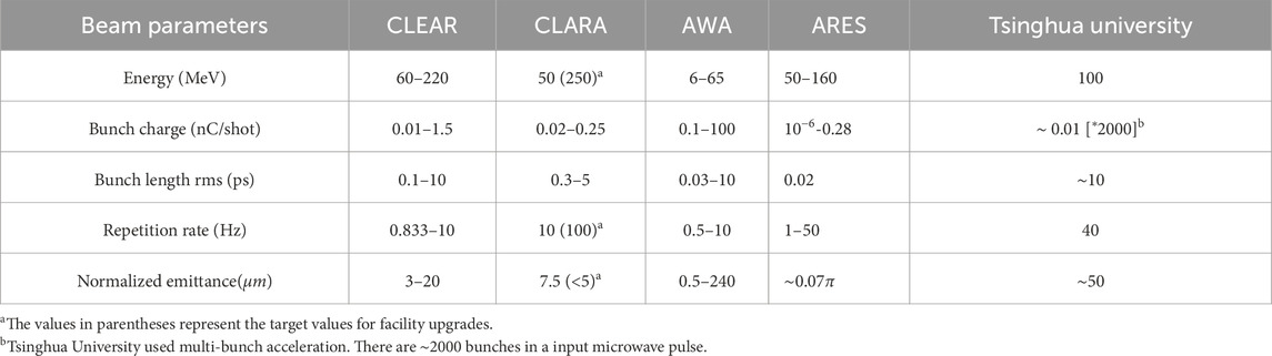
Table 1. Comparison of the parameters of different VHEE facilities.
We employs a commercial klystron with a power output of 50 MW. To minimize the number of klystrons required, a pulse compressor is used to amplify the klystron’s output, reducing both costs and the physical footprint of the installation. The electron source is a hot cathode electron gun, and a buncher focuses the emitted electrons. These are then accelerated by a high-gradient accelerator, enabling a compact design while achieving high-energy output. The VHEE beam line is designed to deliver electrons at 40 Hz, with 24 nC per pulse, generating a dose rate of 40 Gy/s over a
2 Structure layout
Figure 1 presents the schematic diagram of the X-band compact VHEE radiotherapy structure. The power source for the system is a commercial X-band klystron with a 50 MW output, driven by a high-voltage modulator. The microwave signal, originating from the low-level system, is first amplified by a solid-state amplifier before being fed into the klystron.

Figure 1. The X-band compact VHEE structure layout.
After amplification, the klystron’s microwave output is compressed by a pulse compression system and then distributed to the bunching section and two main accelerating sections via the power transmission system. The transmission system employs two directional couplers as power dividers, which, along with loads, minimize interference between the branches. An adjustable power attenuator is placed at the entrance of the bunching section to optimize electron dynamics.
Ensuring that the electric field phase in the main accelerating sections aligns with the phase of the electrons exiting the bunching section is critical. To achieve this, a phase shifter is installed at the entrance of each accelerating section. The X-band high-power phase shifter has an all-metal structure and consists of a dual-polarization mode coupler and a movable piston. Stainless steel loads are positioned at the exits of both the bunching section and the main accelerating sections to absorb the output power from the accelerating tube.
The electron source for the device is a hot cathode electron gun, with detailed parameters provided in Table 2. The low-level system supplies a synchronization signal to the electron gun, ensuring that the electron pulse is synchronized with the microwave pulse output from the klystron.
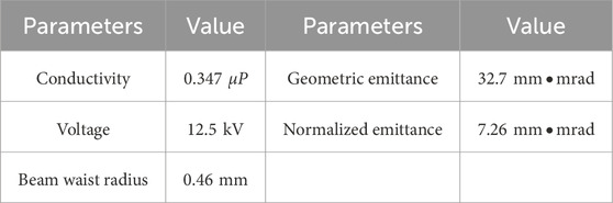
Table 2. Parameters of the hot cathode electron gun.
The following sections will present the beam line’s components, including the power compression system, the backward traveling-wave buncher (BTW), and the constant-gradient traveling-wave accelerator, as well as its preliminary optimization.
3 Components of the beam line
In this section, we will introduce the components of the VHEE beam line, which have been previously studied, including the power compression system, the backward traveling-wave buncher (BTW), and the constant-gradient traveling wave accelerator. These components are critical for achieving the high-gradient acceleration necessary for VHEE radiotherapy applications.
3.1 The pulse compression system
The proposed VHEE radiotherapy structure comprises a power source section and an accelerator section. The power source section occupies a larger area and incurs higher costs. Calculations indicate that using only a 50 MW klystron would require approximately 4 m to accelerate electrons to 100 MeV, while employing multiple klystrons would significantly increase both the spacial requirements and costs. To address this, we have opted to use a pulse compressor capable of achieving a flat-top power gain of three times [30]. This approach increases the gradient of the acceleration structure, allowing the VHEE radiotherapy system to remain compact while utilizing only one klystron.
Figure 2 illustrates the condition and results of the high-power test for the two-stage pulse compressor when it operates at the first-stage. The X-band amplitude modulation (AM) cavity chain features a novel design, where resonant cavities are connected at both ends of the dual-polarization mode coupler. This design reduces both transmission loss and the length of the AM cavity chain to half of its original size. The length of the first-stage compression part of the X-band pulse compression system is only 0.4 m. In high-power tests, a flat-top power gain of three times was achieved, with the amplitude and phase of the flat-top demonstrating good stability, making multi-bunch acceleration feasible. Thus, the first-stage compression section is well-suited for use in the compact VHEE radiotherapy structure.
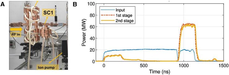
Figure 2. The high-power test of the pulse compression system. (A) Photograph of the pulse compression system after installation. (B) Waveforms of the pulse compressor in high-power test when the second-stage storage cavity was detuned.
3.2 The backward traveling-wave buncher
For the VHEE radiotherapy facility, we developed a prototype of an X-band Backward Traveling Wave (BTW) accelerating structure intended to bunch a DC electron beam and accelerate it to approximately 8 MeV [31]. After optimizing the cavity shape, field distribution, and beam dynamics, the BTW structure was simulated and designed using CST Studio Suite [32]. The simulation results demonstrated a field distribution that closely matches that of the constructed prototype. Additionally, the time-domain circuit model was utilized to analyze the transient beam parameters of the buncher during its unsteady state.
The BTW structure was fabricated at Tsinghua University and underwent high-power test at the Tsinghua X-band High-power Test Stand, as illustrated in Figure 3. The structure was powered by 5 MW microwave pulses from the pulse compressor, operating in one-stage mode (with the second compressor detuned), achieving an average gradient of 45 MV/m. The electron beam was successfully accelerated to 8 MeV, with a pulse current of 108 mA. A comparison between the designed and measured values of the BTW structure is presented in Table 3, where the measured capture rate was calculated by dividing the target current by the gun current. Although some beam parameters did not fully meet the design specifications, the test preliminarily verified the high gradient and large current capabilities of the BTW structure. Future work will focus on addressing fabrication errors in the output coupler to ensure the designed capture rate, and optimizing the magnetic coupling holes between adjacent cells with smooth rounding to improve high-gradient performance.
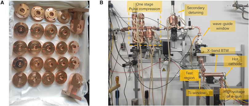
Figure 3. Processing and testing of X-band backward traveling wave buncher. (A) The processed cells and couplers. (B) The high-power beam test of the buncher.
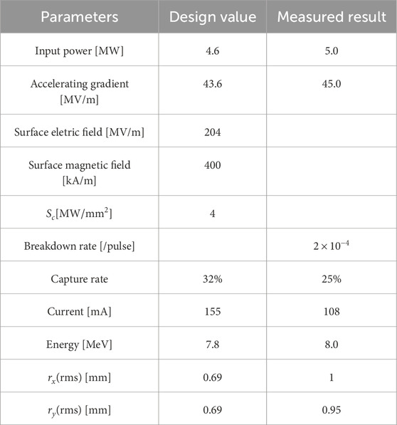
Table 3. Comparison of designed and measured values of the BTW structure.
3.3 The traveling wave accelerator
A constant-impedance traveling-wave structure, consisting of 72 cells operating in the
The XT72 structure comprises 70 accelerating cavities along with input and output couplers. The fabricated cells are shown in Figure 4. When an 80 MW pulse with top drop from the pulse compressor is introduced into the structure, it achieves an average acceleration gradient of 80 MV/m. With a total length of 0.63 m, the structure provides an energy gain of 50 MeV for electrons. The XT72 prototype underwent high-power test, demonstrating better performance compared to the XC72 structure, with an achieved gradient of 81.0 MV/m versus 78.7 MV/m, and a lower breakdown rate (BDR) of
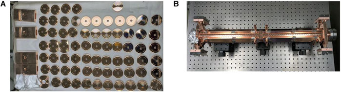
Figure 4. Cells of XT72. (A) Before brazing. (B) After brazing.
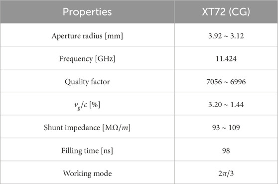
Table 4. RF properties of the XT72.
4 Preliminary optimization of the beam line
After the technology of each component was verified, we preliminarily calculated the particle dynamics of the whole beam line in steady-state, whose results are shown in Figure 5. The layout of the entire beam line is depicted in Figure 5A, which includes a bunching section and two main accelerating sections. Its whole length is less than 2 m. Figure 5B illustrates the electric field along the axis, where the amplitude represents the steady-state value, taking into account the beam loading effect. Figures 5C, D show the variations in energy and envelope for electron beams emitted at different phases, which could preliminarily confirm that the beam line could reach the target electron beam output of 100 MeV. These results were calculated using the equivalent circuit model in the time domain [31].
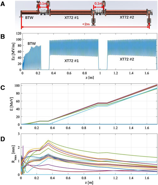
Figure 5. Steady-state dynamics calculation results for the entire beamline. (A) The beamline layout. (B) The electric field along the axis. (C) Electron beam energy at different emission phases. (D) Electron beam envelopes with different emission phases.
After completing the steady-state calculations, we turned to the optimization of the BTW’s parameters, considering the time-domain process within a macro-pulse. The purpose of the optimization is to adjust the filling time of the bunching section to match the time taken by the acceleration section to reach steady-state [36]. The time-domain equivalent circuit model was also applied to this optimization process. Figure 6A shows the transient accelerating voltage in the main accelerating section. Figure 6B illustrates the time-dependent changes of the single-cells’ electric fields within the bunching section. Each color line represents a different cell. These cells’ electric fields correspond to the order of microwave filling. Specifically, the cell next to the input coupler was excited first, therefore reaching its maximum field first. Noting that the bunching section employs a backward traveling wave structure, the microwave filling order proceeds from the exit to the entrance of the beam, therefore the cell next to the output coupler is at the beam entrance. Since the first 4 cells at the beam entrance are critical for beam capture, it is essential that these cells have nearly reached steady-state when the main acceleration section achieves its steady-state condition.
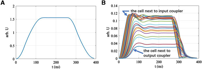
Figure 6. Temporal changes of beam parameters. (A) Main acceleration section: accelerating voltage. (B) Bunching section: single-cell electric fields.
Due to the complexity of multi-objective optimization, we proposed a single-objective approach, prioritizing the electron charge within a specified energy range at the beam line exit. In the preliminary design, the target energy range was set to
5 Results and discussion
5.1 Discussion of beam line optimization
The optimization results of the BTW’s geometric parameters are shown in Figure 7, where the first eight cells are bunching cells and the rest are accelerating cells.
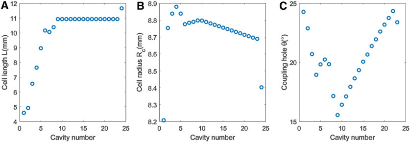
Figure 7. Optimization results of the BTW’s geometric parameters. (A) Cell length. (B) Cell radius. (C) Coupling hole’s angular width.
Figure 8A shows the optimized energy distribution at the beam line exit. Within a macro-pulse, 24 nC of electron charge falls within the
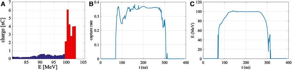
Figure 8. Results of the optimization. (A) Energy distribution of the electron beam at the exit of the VHEE beam line. (B) Transient value of capture rate. (C) Temporal changes of electrons’ average energy at beam exit.
Directly using the electron beam of Figure 8A in VHEE radiotherapy experiments would result in significant background, making it necessary to eliminate or suppress the tail. The most straightforward method is to place a dipole and a slit at the beam exit to filter the electrons by energy, as shown in Figure 9A. While effective in removing the tail, this approach requires a large magnet deflection radius which poses shielding challenges.
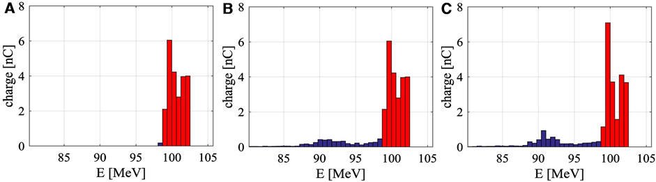
Figure 9. Different methods of removing the beam tail. (A) Using dipoles and slits at the beam line exit. (B) Using dipoles and slits at the bunching section exit. (C) Using a grid-controlled pulsed beam electron gun.
The second method is to position the dipole and slit at the exit of the bunching section. Since the beam energy is lower at this point, the required deflection radius is smaller, making shielding easier. However, calculations indicate that this method can only filter out 55% of the tail, as shown in Figure 9B. This limitation arises because, while some electrons’ energy falls within the specified range upon exiting the bunching section, their large phase deviation causes them to fall outside this range after passing through the acceleration section. Moreover, placing a dipole at the bunching section exit complicates both the microwave and beam systems.
The third method involves using a grid-controlled electron gun with precise beam control, activating the beam when the accelerating structure is nearly filled and deactivating it when input power starts to decline. Since that electrons produced during unsteady states contribute to 76% of the tail distribution, keeping the starting moment of electron emission close to the moment when the accelerator field reaches a steady state may greatly reduce the tail. Considering the beam loading effect, the activating moment is chosen to be when the accelerating structure is nearly filled instead of full filled. The specific activating moment needs to be compared and optimized. Despite this, the unsteady process caused by wakefield effects during beam injection still prevents complete tail removal, as illustrated in Figure 9C.
In summary, while directly screening electrons’ energy at the exit of beam line needs a larger dipole, it is more effective. Future work would be necessary to deal with shielding challenges.
5.2 Discussion of preliminary dose estimate
Based on the optimization of the output charge, the Monte Carlo simulation software GEANT4 [37] was employed to preliminarily calculate the depth-dose distribution of the VHEE beam. To simplify the model, the electron beam was assumed to be parallel after expansion. The parallel beam traverses a 50 cm air gap and then interacts with a 40 cm water layer. The depth-dose distributions at the center of the beams, with cross-sections of
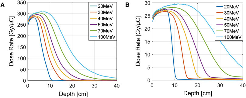
Figure 10. Depth-dose distribution of parallel electron beams with different energies. (A)
It is clear that higher energy levels allow electrons to penetrate deeper into the material. The designed output energy of the VHEE beam line in this study is 100 MeV. By comparing Figures 10A, B, it can be observed that a smaller beam cross-section results in a more rapid fall-off in the depth dose. This is due to increased scattering experienced by electron beams with smaller cross-sections. The dose at a given depth is approximately inversely proportional to the beam’s cross-section area.
For dose estimation, a dose-to-charge ratio of 20 Gy/
Given that the beam line outputs 24 nC per macro pulse and operates at a repetition rate of 40 Hz, the estimated dose rate under a
When the radiation field is reduced to less than
6 Summary
A compact electron accelerator design for VHEE radiotherapy has been proposed, utilizing the Tsinghua X-band High Power Test Stand as its foundation. The pulse compression system, backward traveling-wave buncher, and the prototype high-gradient accelerator, XT72, have each successfully undergone high-power test. At present, the design and optimization of the beam line within a single pulse have been finalized. The whole beam line is still under construction. Ongoing work is focused on wakefield calculations to further refine and optimize the structure for enhanced performance.
Data availability statement
The original contributions presented in the study are included in the article/supplementary material, further inquiries can be directed to the corresponding author.
Author contributions
HL: Writing–original draft, Writing–review and editing. HZ: Writing–review and editing. XL: Writing–review and editing, Writing–original draft. QG: Writing–review and editing. FL: Writing–review and editing. JS: Writing–review and editing. HC: Writing–review and editing.
Funding
The author(s) declare that financial support was received for the research, authorship, and/or publication of this article. We gratefully acknowledge the support of the National Natural Science Foundation of China (NSFC Grant No. 12027902).
Conflict of interest
The authors declare that the research was conducted in the absence of any commercial or financial relationships that could be construed as a potential conflict of interest.
Publisher’s note
All claims expressed in this article are solely those of the authors and do not necessarily represent those of their affiliated organizations, or those of the publisher, the editors and the reviewers. Any product that may be evaluated in this article, or claim that may be made by its manufacturer, is not guaranteed or endorsed by the publisher.
References
1. Vinod SK, Hau E. Radiotherapy treatment for lung cancer: current status and future directions. Respirology (2020) 25:61–71. doi:10.1111/resp.13870
2. Zhang Z, Liu X, Chen D, Yu J. Radiotherapy combined with immunotherapy: the dawn of cancer treatment. Signal Transduction Targeted Ther (2022) 7:258–34. doi:10.1038/s41392-022-01102-y
3. Petroni G, Cantley LC, Santambrogio L, Formenti SC, Galluzzi L. Radiotherapy as a tool to elicit clinically actionable signalling pathways in cancer. Nat Rev Clin Oncol (2022) 19:114–31. doi:10.1038/s41571-021-00579-w
4. De Ruysscher D, Niedermann G, Burnet NG, Siva S, Lee AWM, Hegi-Johnson F. Radiotherapy toxicity. Nat Rev Dis Primers (2019) 5:13–20. doi:10.1038/s41572-019-0064-5
5. Atun R, Jaffray DA, Barton MB, Bray F, Baumann M, Vikram B, et al. Expanding global access to radiotherapy. Lancet Oncol (2015) 16:1153–86. doi:10.1016/S1470-2045(15)00222-3
6. Schaue D, McBride WH. Opportunities and challenges of radiotherapy for treating cancer. Nat Rev Clin Oncol (2015) 12:527–40. doi:10.1038/nrclinonc.2015.120
7. Favaudon V, Caplier L, Monceau V, Pouzoulet F, Sayarath M, Fouillade C, et al. Ultrahigh dose-rate FLASH irradiation increases the differential response between normal and tumor tissue in mice. Sci Translational Med (2014) 6:245ra93. doi:10.1126/scitranslmed.3008973
8. Lin B, Gao F, Yang Y, Wu D, Zhang Y, Feng G, et al. FLASH radiotherapy: history and future. Front Oncol (2021) 11:644400. doi:10.3389/fonc.2021.644400
9. Bourhis J, Montay-Gruel P, Gonçalves Jorge P, Bailat C, Petit B, Ollivier J, et al. Clinical translation of FLASH radiotherapy: why and how? Radiother Oncol (2019) 139:11–7. doi:10.1016/j.radonc.2019.04.008
10. Montay-Gruel P, Bouchet A, Jaccard M, Patin D, Serduc R, Aim W, et al. X-rays can trigger the FLASH effect: ultra-high dose-rate synchrotron light source prevents normal brain injury after whole brain irradiation in mice. Radiother Oncol (2018) 129:582–8. doi:10.1016/j.radonc.2018.08.016
11. Gao F, Yang Y, Zhu H, Wang J, Xiao D, Zhou Z, et al. First demonstration of the FLASH effect with ultrahigh dose rate high-energy X-rays. Radiother Oncol (2022) 166:44–50. doi:10.1016/j.radonc.2021.11.004
12. Fouillade C, Curras-Alonso S, Giuranno L, Quelennec E, Heinrich S, Bonnet-Boissinot S, et al. FLASH irradiation spares lung progenitor cells and limits the incidence of radio-induced senescence. Clin Cancer Res (2020) 26:1497–506. doi:10.1158/1078-0432.CCR-19-1440
13. Chabi S, To THV, Leavitt R, Poglio S, Jorge PG, Jaccard M, et al. Ultra-high-dose-rate FLASH and conventional-dose-rate irradiation differentially affect human acute lymphoblastic leukemia and normal hematopoiesis. Int J Radiat Oncology*Biology*Physics (2021) 109:819–29. doi:10.1016/j.ijrobp.2020.10.012
14. Vozenin MC, De Fornel P, Petersson K, Favaudon V, Jaccard M, Germond JF, et al. The advantage of FLASH radiotherapy confirmed in mini-pig and cat-cancer patients. Clin Cancer Res (2019) 25:35–42. doi:10.1158/1078-0432.CCR-17-3375
15. Simmons DA, Lartey FM, Schüler E, Rafat M, King G, Kim A, et al. Reduced cognitive deficits after FLASH irradiation of whole mouse brain are associated with less hippocampal dendritic spine loss and neuroinflammation. Radiother Oncol (2019) 139:4–10. doi:10.1016/j.radonc.2019.06.006
16. Angal-Kalinin D, Bainbridge A, Brynes AD, Buckley RK, Buckley SR, Burt GC, et al. Design, specifications, and first beam measurements of the compact linear accelerator for research and applications front end. Phys Rev Acc Beams (2020) 23:044801. doi:10.1103/PhysRevAccelBeams.23.044801
17. Abel E, Girdhani S, Jackson I, Eley J, Katsis A, Marshall A, et al. Characterization of radiation-induced lung fibrosis and mode of cell death using single and multi-pulsed proton flash irradiation. Int J Radiat Oncol Biol Phys (2019) 105:E652–3. doi:10.1016/j.ijrobp.2019.06.1033
18. Mascia AE, Daugherty EC, Zhang Y, Lee E, Xiao Z, Sertorio M, et al. Proton FLASH radiotherapy for the treatment of symptomatic bone metastases: the FAST-01 nonrandomized trial. JAMA Oncol (2023) 9:62–9. doi:10.1001/jamaoncol.2022.5843
19. DesRosiers C, Moskvin V, Bielajew AF, Papiez L. 150-250 MeV electron beams in radiation therapy. Phys Med and Biol (2000) 45:1781–805. doi:10.1088/0031-9155/45/7/306
20. Papiez L, DesRosiers C, Moskvin V. Very high energy electrons (50 – 250 MeV) and radiation therapy. Technology Cancer Res and Treat (2002) 1:105–10. doi:10.1177/153303460200100202
21. Lagzda A. VHEE radiotherapy studies at CLARA and CLEAR facilities. United Kingdom), England: The University of Manchester (2019). Ph.D. thesis.
22. Lagzda A, Angal-Kalinin D, Jones J, Aitkenhead A, Kirkby KJ, MacKay R, et al. Influence of heterogeneous media on Very High Energy Electron (VHEE) dose penetration and a Monte Carlo-based comparison with existing radiotherapy modalities. Nucl Instr Methods Phys Res Section B: Beam Interactions Mater Atoms (2020) 482:70–81. doi:10.1016/j.nimb.2020.09.008
23. Poppinga D, Kranzer R, Farabolini W, Gilardi A, Corsini R, Wyrwoll V, et al. VHEE beam dosimetry at CERN Linear Electron Accelerator for Research under ultra-high dose rate conditions. Biomed Phys and Eng Express (2020) 7:015012. doi:10.1088/2057-1976/abcae5
24. Bazalova-Carter M, Liu M, Palma B, Dunning M, McCormick D, Hemsing E, et al. Comparison of film measurements and Monte Carlo simulations of dose delivered with very high-energy electron beams in a polystyrene phantom. Med Phys (2015) 42:1606–13. doi:10.1118/1.4914371
25. Dunning MP, Adolphsen C, Chu TS, Colby ER, Gilevich A, Hast C, et al. Status and upgrades of the NLCTA for studies of advanced beam acceleration, dynamics, and manipulation. In: Proceedings of 2011 particle accelerator conference. New York, USA (2011).
26. Gamba D, Corsini R, Curt S, Doebert S, Farabolini W, Mcmonagle G, et al. The CLEAR user facility at CERN. Nucl Instr Methods Phys Res Section A: Acc Spectrometers, Detectors Associated Equipment (2018) 909:480–3. doi:10.1016/j.nima.2017.11.080
27. Conde ME, Antipov SP, Doran DS, Gai W, Gao Q, Ha G. Research program and recent results at the argonne wakefield accelerator facility (AWA). In: Proceedings of the 8th international particle accelerator conference. Copenhagen, Denmark (2017). doi:10.18429/JACoW-IPAC2017-WEPAB132
28. Burkart F, Assmann R, Dinter H, Jaster-Merz S, Kuropka W, Mayet F, et al. The ares linac at desy. In: Proceedings of the 31st international linear accelerator conference. Liverpool, UK (2022). doi:10.18429/JACoW-LINAC2022-THPOJO01
29. Wanstall HC, Burkart F, Dinter H, Kellermeier M, Kuropka W, Mayet F, et al. First in vitro measurement of VHEE relative biological effectiveness (RBE) in lung and prostate cancer cells using the ARES linac at DESY. Scientific Rep (2024) 14:10957. doi:10.1038/s41598-024-60585-7
30. Lin X, Zha H, Shi J, Jiang Y, Hu F, Gu W, et al. X-band two-stage rf pulse compression system with correction cavity chain. Phys Rev Acc Beams (2022) 25:120401. doi:10.1103/PhysRevAccelBeams.25.120401
31. Lin XC, Zha H, Shi JR, Gao Q, Hu FJ, Li QZ, et al. A compact X-band backward traveling-wave accelerating structure. Nucl Sci Tech (2024) 35:40. doi:10.1007/s41365-024-01403-7
32. Available from: https://www.cst.com/ (Accessed January 07, 2025).
33. Lin XC, Zha H, Shi JR, Gao Q, Liu JY, Zhou LY, et al. Fabrication, tuning, and high-gradient testing of an X-band traveling-wave accelerating structure for VIGAS. Nucl Sci Tech (2022) 33:102. doi:10.1007/s41365-022-01086-y
34. Yingchao D, Han C, Hongze Z, Qiang G, Qili T, Zhijun C, et al. A very compact inverse Compton scattering gamma-ray source. High Power Laser Part Beams (2022) 34:104010–9. doi:10.11884/HPLPB202234.220132
35. Gao Q, Zha H, Shi J, Lin X, Du Y, Feng B, et al. Design and test of an X-band constant gradient structure. Phys Rev Acc Beams (2024) 27:090401. doi:10.1103/PhysRevAccelBeams.27.090401
36. Liu JY, Shi JR, Zha H, Grudiev A, Wang P, Du YC, et al. Analytic RF design of a linear accelerator with a SLED-I type RF pulse compressor. Nucl Sci Tech (2020) 31:107. doi:10.1007/s41365-020-00815-5
37. Available from: https://geant4.web.cern.ch/ (Accessed January 07, 2025).
Keywords: VHEE, FLASH radiotherapy, linac accelerator, X-band high gradient, beam line
Citation: Li H, Zha H, Lin X, Gao Q, Liu F, Shi J and Chen H (2025) Design of a 100-MeV compact VHEE beam line in Tsinghua University. Front. Phys. 12:1496272. doi: 10.3389/fphy.2024.1496272
Received: 14 September 2024; Accepted: 27 December 2024;
Published: 15 January 2025.
Edited by:
Xun Jia, Johns Hopkins Medicine, United StatesReviewed by:
Yan-Fei Li, Xi’an Jiaotong University, ChinaYujie Chi, University of Texas at Arlington, United States
Copyright © 2025 Li, Zha, Lin, Gao, Liu, Shi and Chen. This is an open-access article distributed under the terms of the Creative Commons Attribution License (CC BY). The use, distribution or reproduction in other forums is permitted, provided the original author(s) and the copyright owner(s) are credited and that the original publication in this journal is cited, in accordance with accepted academic practice. No use, distribution or reproduction is permitted which does not comply with these terms.
*Correspondence: Jiaru Shi, c2hpakB0c2luZ2h1YS5lZHUuY24=