- 1School of Physics, Harbin Institute of Technology, Harbin, China
- 2School of Electrical Engineering and Automation, Harbin Institute of Technology, Harbin, China
- 3Laboratory for Space Environment and Physical Science, Harbin Institute of Technology, Harbin, China
- 4Southwestern Institute of Physics, Chengdu, China
As a high heat flux linear plasma device designed for studying divertor materials in future fusion reactors, HIT-PSI(Plasma Surface Interaction device at Harbin Institute of Technology) has been successfully constructed and has maintained stable operation since its completion. The characteristics of He plasma beams in HIT-PSI are investigated by emission spectroscopy and an infrared camera, with preliminary irradiation experiments conducted by bombarding tungsten with the beam. For relatively conservative discharge parameters, HIT-PSI achieved a steady-state heat flux capacity of ∼40 MW/m2 using infrared measurements, with the full width at half maximum (FWHM) of the heat flux beam reaching 4 mm. These characteristics make HIT-PSI an advanced platform for testing divertor materials and plasma-facing components, providing essential experimental supports for research and development of high-performance divertor materials.
1 Introduction
The performance of materials for the tokamak divertor target and other plasma-facing components (PFCs) is critical to determining their reliability [1–5]. As fusion devices advance towards reactor parameter regimes, the expected high heat flux will exceed 10 MW/m2 in divertor regions [6], accompanied by highly high particle flux. Nevertheless, most existing divertors of fusion devices, generally operate with short discharge pulses and relatively low heat flux on their target plates, significantly below the requirement for future fusion reactors [7–10].
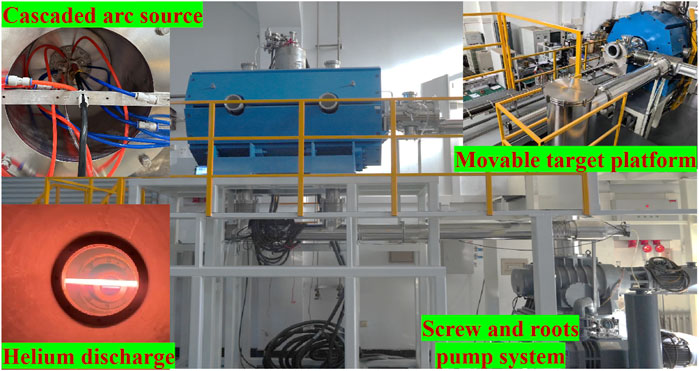
To further evaluate and optimize the performance of PFC materials, various linear plasma devices (LPDs) have been developed as test platforms to experimentally simulate plasma surface interactions (PSIs) in future fusion reactors [11–18], mainly focusing on the study of tungsten [19, 20]. Characterized by a simple structure and low cost, enable flexible magnetic field configurations by various plasma sources to simulate plasma temperatures and densities similar to those in fusion reactor boundary regions, LPDs have been widely used in research areas of plasma physics and applications, particularly for simulating significant physical processes in divertor/scrape-off-layer (D-SOL) environments. For instance, Pilot-PSI [21, 22] employs a cascaded arc plasma source capable of generating high magnetic fields in short pulses, up to 1.6 T for a few seconds, to produce hydrogen plasma beams with electron density of 5 × 10²¹ m−3 and electron temperature of 3 eV. The next-generation LPD, Magnum-PSI [23–26], designed and constructed based on the experience from Pilot-PSI, achieves steady-state particle flux >1025 m-2s−1 and heat flux >50 MW/m2 [26]. At Oak Ridge National Laboratory (ORNL), MEPX uses a helicon source in a confinement magnetic field of ∼1.4 T and with additional heating methods, e.g., ECRH and ICRH, for a designed power of ∼1 MW [27, 28]. Recently, another high heat flux simulation facility for PSIs known as HIT-PSI [29] at Harbin Institute of Technology (HIT) has been designed and is now in operation. As illustrated in Figure 1, this facility utilizes a cascaded arc plasma source in a high magnetic field exceeding 2 T generated by superconducting magnets to simulate characteristics of extreme heat and particle flux in divertor region.
Supported by these devices, the physical simulation of LPDs, such as that in HIT-PSI and other devices, allows for a more intuitive understanding transport characteristics in the D-SOL region, and particularly provides crucial support for the studies on high heat load effects. First, the similarity between the LPDs (such as HIT-PSI and other similar devices) and the D-SOL region of tokamaks makes it an appreciated platform for studying edge physics in fusion plasmas [30, 31]. In an open magnetic field environment similar to that in the D-SOL region of tokamaks, the LPD can effectively simulate feature transport processes of D-SOL plasmas [31–33]. Nevertheless, the toroidal geometry feature of tokamaks other than that in LPDs may cause the notable drift effect on transport, leading to limitations in LPD physical simulations [34]. For HIT-PSI, the plasma beta is designed and experimentally estimated 10–5∼10–4, in the range of D-SOL plasmas of existing tokamaks and future reactors (e.g., ∼10–5 for ITER [35]). Also, the normalized collision rate (by the electron gyro-frequency) in HIT-PSI is 10–3∼10–2, much higher than that for tokamak D-SOL plasmas (e.g., 10–5∼10–4 for ITER [35]). To present the divertor target property, the ratio of Debye length, which features the target sheath thickness, to the electron gyroradius is 10–1∼100, also in the same range as for ITER (∼100) [35]. Additionally, the electron temperature in LPDs is typically lower (ranging from a few eV to tens of eV [26, 36]), allowing for detached state research. Most prominently, HIT-PSI can achieve a parameter range much higher than that of existing tokamak devices but of the future reactor regime, in steady-state operations. Particularly, HIT-PSI is capable to generate a high heat flux density of
This study focused on the characterization of helium plasma beams generated in HIT-PSI with high magnetic fields. Optical emission spectroscopy was then employed to measure the plasma’s spectral characteristics beam at different magnetic field strengths and gas flow conditions and excitation temperatures were calculated. An infrared camera was used to evaluate the heat flux capacity of the device. Irradiation experiments were also conducted for pure tungsten samples. In steady-state operations of HIT-PSI, even for relatively conservative discharge parameters, the heat flux of helium plasma beams can reach up to 40 MW/m2, demonstrating the experimental capability to simulate processes equivalent to those in the divertor environment.
The arrangement of this paper is as follows: Section 2 introduces the experimental setups. The results and analysis of emission spectroscopy, infrared diagnostics, and tungsten irradiation are presented in Section 3. The final section provides a conclusion.
2 Experiment setup
The HIT-PSI device (Figure 1) is operated in a 2 m long chamber by superconducting magnets, capable of reaching a magnetic field of up to 2.5 T, with a uniform magnetic field region >1 m and 8 radial boreholes to allow for flexible configuration of the vacuum system and diagnostic equipment. The plasma is generated by a cascaded arc source to generate a steady-state high-density plasma beam. The pumping system, consisting of screw and root pumps, achieves a pumping speed of 2500 L/s, maintaining a background pressure of 0.01 Pa. The movable target platform allows for changing the irradiation platform position axially.
A schematic diagram of the experimental setup is presented in Figure 2A. The discharge gas used in experiments is pure helium (He), with gas flow rates controlled at 1.4 slm, 1.7 slm, and 2.1 slm, respectively, corresponding to vacuum chamber pressures of 3.0 Pa, 3.5 Pa, and 4.0 Pa measured by an INFICON capacitance diaphragm gauge (Model CDG025). The collection point for emission spectroscopy and the infrared camera are both at Window 1, 25 cm from the plasma source outlet. Three axial magnetic fields are applied, corresponding to coil currents of 120 A, 170 A, and 230 A, producing field intensities of approximately 2.0 T (C1), 1.5 T (C2), and 1.0 T (C3),as shown in Figure 2B.

Figure 2. Schematic diagram of (A) the infrared radiation (IR) and optical measurement arrangement and (B) the experimental magnetic field conditions.
Optical emission spectra are collected with a Princeton Instruments (PI) SP-2750 spectrometer and a MAX4 1024i ICCD. Two diffraction gratings are utilized, one with a groove density of 300 g/mm and the other with 2,400 g/mm. Optical transmission is achieved through a UV-VIS fiber bundle (Model LG-455-020-3). The focusing optics consists of a fused silica plano-convex lens, 50.8 mm in diameter and 200 mm in focal length. Wavelength calibration is carried out by an AvaLight-HAL-CAL-Mini, while intensity calibration is performed with a PI intensity lamp in conjunction with the IntelliCal® system.
For heat flux measurement, real-time surface temperature changes of the graphite block under plasma beam bombardment are captured and recorded by the infrared camera. Then, a three-dimensional heat conduction equation was applied to calculate the heat flux of the plasma beam. A graphite cube with an 80 mm edge length is placed at Window 1, resting on a zirconia ceramic plate with a significantly lower thermal conductivity than graphite to ensure adiabatic conditions for the graphite during irradiation. The FLIR A700sc infrared camera, operating within the 7.5–14.0 µm wavelength range, is positioned at Window 1, perpendicular to the beam transmission direction. The Plasma Beam Facing Surface (PBFS) of the graphite cube is tilted 30° to the chamber symmetric axis to facilitate the observation of temperature changes on the surface with the infrared camera. The observation window is made of optical-grade ZnSe with a special coating, ensuring an infrared transmission rate of over 95% in a 6–14 µm wavelength range. The acquisition frequency is fixed at 30 Hz. Before experimental measurements, the infrared camera is placed behind the ZnSe window and calibrated by a standard heat source, with the infrared emissivity of the graphite cube surface measured at the same 30-degree angle setting. The thermal conductivity of the graphite is measured by a laser flash method and fitted to an exponential function as.
where T is the temperature in Kelvin (K), and other parameters are listed in Table 1.
The irradiated sample is a circular pure tungsten disk with a diameter of 30 mm and a thickness of 4 mm. The irradiation location is also at Window 1, with the sample fixed onto a water-cooled target plate. The back of the sample remains in contact with a water-cooled copper plate, facilitating the cooling process by heat conduction during irradiation. To easily observe the practical interaction between the sample and the plasma, the entire target is positioned on a movable platform, and the samples undergo irradiation experiments under two conditions: without an applied bias and with a bias of −80 V. After finishing the irradiation, the sample is first cooled and then exposed to atmospheric pressure, followed by Scanning Electron Microscope analysis.
3 Results and discussion
In this section, Section 3.1 will introduce the measurement and analysis of the spectral characteristics of the He plasma beam using emission spectroscopy under different magnetic fields, while Section 3.2 will present the measurement results of the heat flux of the HIT-PSI device using an infrared (IR) camera. Section 3.3 provides preliminary results of the irradiation of pure tungsten target plates with the He plasma beam.
3.1 Emission spectral characteristics of He plasma in strong magnetic fields
Figure 3 presents a comparison of the spectral intensities as the gas flow rate increases from 1.4 slm to 2.1 slm and the pressure rises from 3.0 Pa to 4.0 Pa at C1, and Figure 5A gives the intensity ratios of the main He I spectral lines. The substantial enhancement in line intensity indicates a significant increase in the density of excited atoms due to increased gas flow. This increase in gas flow can simultaneously raise the electron temperature and density to some extent, as demonstrated in experiments conducted on other experimental setups [41, 42].
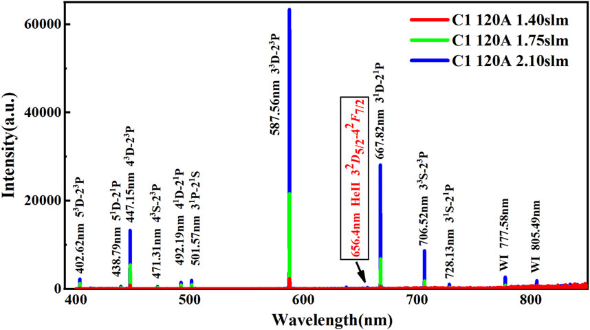
Figure 3. Typical spectra of the He plasma beam at different gas flow rates at C1 and a discharge current of 120 A.
Figure 4 compares the spectra in different magnetic fields (C1, C2, and C3) at a discharge current of 120 A and a gas flow rate of 2.1 slm. The differences in spectral lines of various cases are minimal. The simple and stable energy level structure of helium atoms results in a high probability of spontaneous emission for strong He I lines during transitions from excited states to the ground state. The plasma produced by the cascaded arc source has a relatively low electron temperature (˂5 eV) [23, 43–45], challenging to excite a transition to higher energy levels. Thus, the transitions mainly concentrated on a few strong lines at lower energy levels. Such factors together lead to main spectral profiles without significant differences in the three magnetic field conditions.
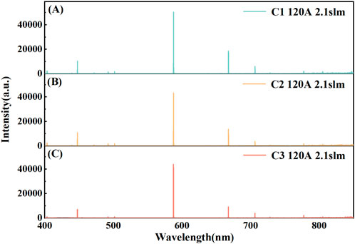
Figure 4. Typical spectra of He plasma beams at C1(A), C1(B) and C1(C) with a discharge current of 120 A and a gas flow rate of 2.1 slm.
Figure 5B presents the intensity ratios of the main He I spectral lines at different magnetic field conditions, with all lines normalized by that of C1. The results indicate that as the magnetic field strengthens, the line intensity increases, particularly as comparing the lines for C1 and C3 with the more pronounced magnetic field difference. The presence of a strong magnetic field induces a noticeable Zeeman effect, resulting in broader spectra and much more apparent intensity differences. The excitation of helium atoms primarily occurs by collision and recombination excitations (including radiative and three-body recombinations). Near the exit of the plasma source, the electron temperature is relatively high [46], which makes collisional ionization and excitation the dominant processes, with electron collisions to ground-state helium atoms being the primary excitation mechanism. At stronger magnetic fields, the beam is better confined, radial diffusion, and the density is better maintained. Additionally, the power supply voltage for the plasma source increases from 107.0 V at C3 to 119.8 V at C2, and to 126.5 V at C1, indicating that more energy is coupled into the plasma as the magnetic field strengthens, leading to an increase in electron temperature. Furthermore, a weak He II 656.4 nm line appears in the spectrum, indicating an increase in the number of high-energy electrons. Consequently, the spectral intensity is higher at stronger magnetic fields.
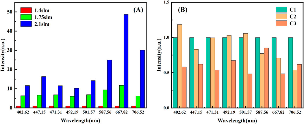
Figure 5. (A) Intensity ratios of the main He I spectral lines at different gas flow rates at C1 and a discharge current of 120 A, with normalization to the spectral intensity at C1. (B) Intensity ratios of the main He I spectral lines at different magnetic field conditions at a gas flow rate of 1.4 slm and a discharge current of 120 A, with normalization to the spectral intensity at C1.
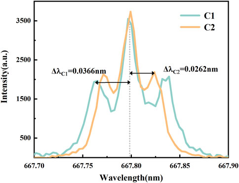
At high magnetic fields, the spectral lines exhibit significant Zeeman splitting, which complicates the calculation of parameters with broadening. Figure 6 shows the Zeeman splitting of He I 667.8 nm line (21 P-31D), clearly observed at C1 and C2. However, this splitting can be used to calculate the magnetic field accurately. The splitting caused by the Zeeman effect can be written [47].
where
By selecting the spectral lines from the characteristic spectrum listed in Table 2, we can construct the Boltzmann plot depicted in Figure 7A, in which the variation in electron excitation temperature can be determined. Figure 7B shows the excitation temperatures calculated using the Boltzmann slope method for different magnetic fields (with a discharge current of 120 A), as well as various discharge currents and gas flow rates (at C1). It can be observed that excitation temperatures do not exceed 1 eV, significantly differing from the actual electron temperature and indicating non-equilibrium plasmas and insufficient collisions [15, 48]. In this region, near the plasma source exit, where both electron temperature and density are high, collisional ionization dominates. The collisional ionization process mainly involves high-energy electrons, and their reduction in number and insufficient collisions likely lead to non-Maxwellian distribution characterized by a lack of high-energy electrons. This could be the reason for the lower excitation temperature.
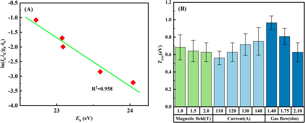
Figure 7. Boltzmann plot of the He I spectral lines (A) and electron excitation temperature at three different magnetic fields (B).
As shown in Figure 7B, the electron excitation temperature shows a slight downward trend as the magnetic field increases but generally remains stable overall. Thomson scattering measurements on the Pilot-PSI and Magnum-PSI device indicated that electron temperature and density rise with a stronger magnetic field, leading to an increased ionization rate [22, 49]. Consequently, more high-energy electrons are consumed in the ionization process, leading to a slight decrease in electron excitation temperature, which remains significantly lower than the overall electron temperature.
The electron excitation temperature shows a slight upward trend as the discharge current increases, depicted in Figure 7B. The increase in the discharge current leads to a rise in both electron temperature and density [50], increasing the frequency of collisional excitation processes, to induce a modest rise in the electron excitation temperature. However, since most high-energy electrons are still primarily involved in the ionization process, the increase in excitation temperature is relatively limited. Additionally, the increase in discharge current enhances the collision frequency between electrons and other particles and potentially facilitates energy redistribution among electrons, to increase a faster participation of higher energy electrons in excitation processes. Nevertheless, since most higher energy electrons are still consumed in the ionization process, the rise in excitation temperature remains modest.
As indicated in Figure 7B, the electron excitation temperature noticeably drops with the increase in gas flow. An increase in the gas flow rate raises not only the electron temperature and density of the beam but also the density of heavy particles, leading to a higher collision frequency between electrons and heavy particles. As shown in Figure 3, the number of excited-state atoms rises sharply, resulting in depletion of higher energy electrons and thereby lowering the excitation temperature.
3.2 Heat flux measurement by infrared camera
Infrared camera images captured during the discharge process are shown in Figure 8. The region marked Px1 is the PBFS of the graphite block, reconstructed into a square with a side length of 80 mm in subsequent data processing. Due to limitations of the camera acquisition range, the heating process beyond the selected range cannot be measured in a single run. Therefore, the acquisition is divided into two stages: the first stage measures temperatures in the 0°C–650°C range, and the second in the 300°C–2000°C range. Figure 8 shows real-time images of the two-step temperature measurement. The data above 500°C by the second acquisition are overlaid on the first acquisition data to create a composite temperature profile.

Figure 8. Real-time temperature measurement of helium discharges as displayed by the infrared camera. (A) Before discharge, the area marked by the red dashed circle indicates the region that was previously irradiated by the beam. (B) Measurement range is 0°C–650°C (C) Measurement range is 300°C–2000°C.
The heat flux is predicted by analyzing the surface heat flux based on the three-dimensional (3D) heat conduction equation to compute the temperature variations within the graphite block, given by the following formula [51]:
where
The PBFS is set at z = 0 plane, while the non-PBFSs follow the adiabatic boundary condition of
Heat flux can then be determined by
To enhance the computational efficiency of solving the three-dimensional heat conduction equation, an alternating direction implicit (ADI) algorithm is employed to reduce each step’s complexity and significantly improve the computing speed and efficiency. Furthermore, the ADI algorithm has high accuracy and is suitable for various practical applications in 3D heat conduction. Also, the implemented code is rigorously validated by COMSOL and ANSYS results, ensuring its reliability and precision.
Figure 9A depicts the temperature distribution on the graphite strike face (PBFS), measured by the infrared thermography approximately at the fifth second after the discharge onset, with discharge current of 120 A at C1. The temperature profile exhibits a Lorentzian distribution, with the core temperature reaching a significantly high value. Figure 9B presents the temporal evolution of the core temperature. Notably, at less than 1/3 s from the onset, the core temperature rapidly escalates to >1,000°C. After such a rapid rise, there is a slight decrease in temperature, succeeded by another rise. The cause of this temperature fluctuation may be surface modifications or damage caused by the high heat flux, which fundamentally alters the initial graphite surface morphology.
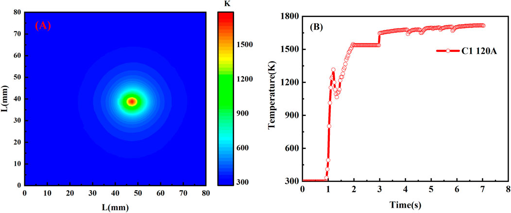
Figure 9. At C1 with discharge current of 120 A and gas flow rate of 1slm, (A) at approximately the fifth second, the synthesized surface temperature distribution with a maximum temperature >1700 K; (B) the temperature variation vs. time at the center point of the beam.
The two-dimensional (2D) and radial distributions of the beam heat flux with discharge current of 120 A and a conservative gas flow rate of 1.4 slm at three distinct magnetic field conditions (C1, C2, C3) are shown in Figure 10. The heat flux can easily exceed 20 MW/m2. With the increase in magnetic field strength, a significant enhancement in heat flux is observed, reaching up to 40 MW/m2 at C1. Figure 11A presents the 2D beam heat flux profile distribution, which exhibits a quasi-Gaussian shape with no substantial variations across different conditions. The full width at half maximum (FWHM) remains approximately 4 mm, consistent with the size of the plasma source exit. Figure 11B presents the steady-state heat flux at different field and current conditions. The steady-state heat load easily exceeds 20 MW/m2, with the beam demonstrating good stability. At higher magnetic fields, the heat flux density curve shows fluctuations during the initial stage and then gradually reaches a steady state. It may be attributed to the rapid changes in surface temperature and physical alterations in surface morphology, leading to variations in temperature measurements. However, the overall trend is clear: stronger magnetic fields and higher currents result in greater heat flux.

Figure 10. Heat flux spots at C1 (A), C2 (B), and C3 (C), respectively, with discharge current of 120 A and a gas flow rate of 1.4 slm at C1.
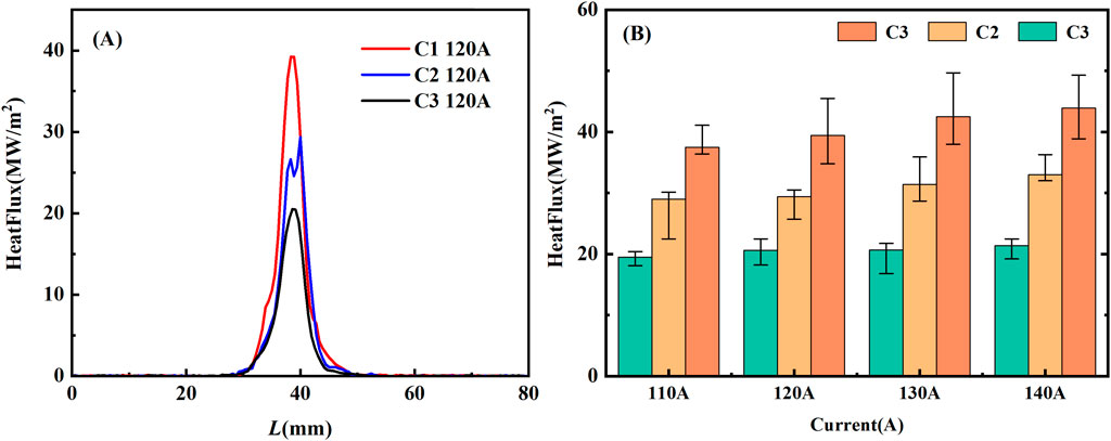
Figure 11. (A) The distribution of steady-state heat flux along the vertical direction in Figure 10 and (B) the steady-state heat flux values at different magnetic fields and discharge currents.
It should be noted that, due to the angle between the plasma beam and PBFS of the graphite block, along with the relatively low gas flow rate, the current heat flux represents a conservative estimate of the device’s capabilities, while the actual heat flux achievable by HIT-PSI could be higher. As the magnetic field increases, the power of the plasma source accordingly rises, too, which has been confirmed in our device and other experiments [22, 25, 42]. This enables more power to be coupled into the plasma beam, leading to an increase in the electron temperature and density. Additionally, the strong magnetic field provides better confinement of the plasma, reducing radial diffusion and increasing plasma density. Ultimately, this effect significantly enhances the heat flux of the helium beam at a strong magnetic field.
When the beam reaches Window 2, at a transmission distance of 120 cm, it undergoes significant attenuation. At C3, the beam is almost invisible to the naked eye. In the parameter regime of our experiments, where electron and ion temperatures are approximately below 5 eV [52] and based on elastic collision parameters [53, 54], the collision rates of ions and electrons with atoms in He discharges are estimated in the ranges of 106 Hz and 107 Hz respectively. The characteristic axial propagation period of the beam is approximately 10–3 to 10–4 s, accordingly. Such features indicate that during the beam transmission, both electrons and ions undergo numerous collisions with background neutral helium atoms, resulting in significant energy transfer to the background and rapid energy loss from the beam. At the sufficiently high confining magnetic field in HIT-PSI, the impact of radial diffusion of the beam heat flux is far less significant than that of collision effects. To further increase the heat flux, the most effective way is to reduce the background gas pressure.
3.3 Initial experiment of he plasma beam irradiation on tungsten
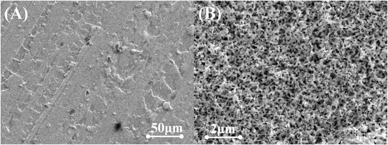
The irradiation results without an applied bias are shown in Figure 12. The surface irregularity in the non-irradiated sample shown in Figure 12A is due to the polishing process, with noticeable cutting marks. The tungsten surface after 30 s of irradiation shows signs of melting. As the irradiation goes on, noticeable uneven coral-like structures on the surface are shown in Figure 12C after 60 s, and then cracks appear in Figure 12D after 120 s. Further tracing the irradiation to 240 s, the surface exhibits a granular texture in Figures 12E, F. Larger scale SEM images reveal extensive areas of granules in the micron scale, a sign of recrystallization.
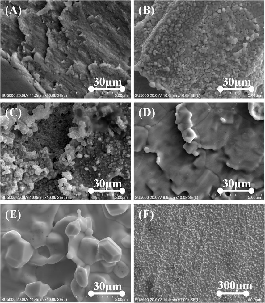
Figure 12. SEM images of W samples under different irradiation durations without bias, with the measurement moments at (A) 0 s, (B) 30 s, (C) 60 s, (D) 120 s, and (E, F) 240 s.
The irradiation results with an applied bias of −80 V are shown in Figure 13. After just 30 s of irradiation, the tungsten sample’s surface has formed a distinct “fuzzy” structure. Typically, the formation of such a structure is considered to require a helium particle flow reaching 1025 m−2 [55, 56]. This indicates that the particle flux capability of HIT-PSI has reached a significantly high level. We will gradually improve the measurement of critical parameters for irradiation, such as sample temperature and particle flow, to achieve more precise and systematic experiments that comprehensively simulate the service environment for divertor materials and components under high heat flux and high particle flow irradiation conditions. This will provide experimental data to support the development of new methods and approaches for enhancing the service conditions of divertor target materials in fusion research facilities.
4 Conclusion
The emission spectra and heat flux characteristics of the He plasma beam are measured at different high magnetic field conditions, and preliminary irradiation experiments on pure tungsten samples are carried out. This study reveals that the heat flux capacity of HIT-PSI can exceed 40 MW/m2, far surpassing the initial design target and effectively simulating the extreme heat flux conditions expected in the divertor region of future fusion reactors.
Additionally, the emission spectrum of helium at high magnetic field conditions exhibits a consistent pattern, but the overall spectral intensity significantly rises as the gas flow increases. Preliminary irradiation experiments demonstrate that HIT-PSI can serve as an excellent platform for testing the performance of plasma-facing materials and components in extreme irradiation environments and providing valuable insights for future research and materials development.
Data availability statement
The raw data supporting the conclusions of this article will be made available by the authors, without undue reservation.
Author contributions
TH: Conceptualization, Data curation, Formal Analysis, Investigation, Methodology, Project administration, Validation, Visualization, Writing–original draft, Writing–review and editing. QN: Conceptualization, Data curation, Formal Analysis, Funding acquisition, Investigation, Methodology, Project administration, Resources, Supervision, Validation, Visualization, Writing–review and editing. TJ: Data curation, Investigation, Writing–original draft. CC: Data curation, Investigation, Writing–original draft. YL: Data curation, Investigation, Writing–original draft. JG: Data curation, Formal Analysis, Investigation, Methodology, Validation, Writing–review and editing. LC: Data curation, Formal Analysis, Investigation, Methodology, Validation, Writing–review and editing. XZ: Data curation, Investigation, Writing–original draft. XW: Conceptualization, Data curation, Formal Analysis, Funding acquisition, Investigation, Methodology, Project administration, Resources, Supervision, Validation, Writing–review and editing.
Funding
The author(s) declare that financial support was received for the research, authorship, and/or publication of this article. This work is supported by the National Natural Science Foundation of China No.12105067.
Conflict of interest
The authors declare that the research was conducted in the absence of any commercial or financial relationships that could be construed as a potential conflict of interest.
Publisher’s note
All claims expressed in this article are solely those of the authors and do not necessarily represent those of their affiliated organizations, or those of the publisher, the editors and the reviewers. Any product that may be evaluated in this article, or claim that may be made by its manufacturer, is not guaranteed or endorsed by the publisher.
References
1. Merola M, Loesser D, Martin A, Chappuis P, Mitteau R, Komarov V, et al. ITER plasma-facing components. Fusion Eng Des (2010) 85:2312–22. doi:10.1016/j.fusengdes.2010.09.013
2. Luo GN, Zhang XD, Yao DM, Gong XZ, Chen JL, Yang ZS, et al. Overview of plasma-facing materials and components for EAST. Physica Scripta (2007) T128:1–5. doi:10.1088/0031-8949/2007/t128/001
3. Linke J, Du J, Loewenhoff T, Pintsuk G, Spilker B, Steudel I, et al. Challenges for plasma-facing components in nuclear fusion. Matter Radiat Extremes (2019) 4:5. doi:10.1063/1.5090100
4. Luo G-N, Liu G, Li Q, Qin S, Wang W, Shi Y, et al. Overview of decade-long development of plasma-facing components at ASIPP. Nucl Fusion (2017) 57(6):065001. doi:10.1088/1741-4326/aa6502
5. Herrmann A. Overview on stationary and transient divertor heat loads. Plasma Phys controlled fusion (2002) 44(6):883–903. doi:10.1088/0741-3335/44/6/318
6. Linke J. High heat flux performance of plasma facing materials and components under service conditions in future fusion reactors. Fusion Sci Technol (2006) 49(2T):455–64. doi:10.13182/fst06-a1144
7. Holtkamp N. ITER Project Team. An overview of the ITER project. Fusion Eng Des (2007) 82(5-14):427–34. doi:10.1016/j.fusengdes.2007.03.029
8. Zhuang G, Li GQ, Li J, Wan Y, Liu Y, Wang X, et al. Progress of the CFETR design. Nucl Fusion (2019) 59(11):112010. doi:10.1088/1741-4326/ab0e27
9. Hirai T, Barabash V, Escourbiac F, Durocher A, Ferrand L, Komarov V, et al. ITER divertor materials and manufacturing challenges. Fusion Eng Des (2017) 125:250–5. doi:10.1016/j.fusengdes.2017.07.009
10. Pitts RA, Bonnin X, Escourbiac F, Frerichs H, Gunn J, Hirai T, et al. Physics basis for the first ITER tungsten divertor. Nucl Mater Energy (2019) 20:100696. doi:10.1016/j.nme.2019.100696
11. Uccello A, Bin W, Bruschi A, Causa F, Cremona A, De Angeli M, et al. Linear plasma device GyM for plasma-material interaction studies. Front Phys (2023) 11:1108175. doi:10.3389/fphy.2023.1108175
12. Nishijima D, Wenzel U, Ohsumi K, Ohno N, Uesugi Y, Takamura S. Characteristics of detached plasmas associated with electron-ion and molecular assisted recombinations in NAGDIS-II. Plasma Phys Control Fusion (2002) 44(5):597–610. doi:10.1088/0741-3335/44/5/307
13. Kreter A, Brandt C, Huber A, Kraus S, Möller S, Reinhart M, et al. Linear plasma device PSI-2 for plasma-material interaction studies. Fusion Sci Technol (2015) 68(1):8–14. doi:10.13182/fst14-906
14. Unterberg B, Jaspers R, Koch R, Massaut V, Rapp J, Reiter D, et al. New linear plasma devices in the trilateral euregio cluster for an integrated approach to plasma surface interactions in fusion reactors. Fusion Eng Des (2011) 86(9-11):1797–800. doi:10.1016/j.fusengdes.2011.03.082
15. Kakati M, Sarmah T, Aomoa N, Sabavath G, Dihingia P, Rahman M, et al. Design, development and recent experiments of the CIMPLE-PSI device. Nucl Fusion (2019) 59(11):112008. doi:10.1088/1741-4326/ab0248
16. Nakashima Y, Takeda H, Ichimura K, Hosoi K, Oki K, Sakamoto M, et al. Progress of divertor simulation research toward the realization of detached plasma using a large tandem mirror device. J Nucl Mater (2015) 463:537–40. doi:10.1016/j.jnucmat.2014.12.063
17. Zhou HS, Yuan XG, Li B, Liu HD, Luo GN, Chen JL, et al. A new high flux plasma source testing platform for the CRAFT project. J Fusion Energy (2020) 39:355–60. doi:10.1007/s10894-020-00277-y
18. Sun C, Sang C, Ye H, Wang Q, Liu H, Wang Z, et al. The design of multiple plasma simulation linear device. Fusion Eng Des (2021) 162:112074. doi:10.1016/j.fusengdes.2020.112074
19. Yin H, Wang J, Guo W, Cheng L, Yuan Y, Lu G. Recent studies of tungsten-based plasma-facing materials in the linear plasma device STEP. Tungsten (2019) 1(2):132–40. doi:10.1007/s42864-019-00004-x
20. Sakamoto R, Elodie B, Arkadi K, Celine M. Impact of helium and hydrogen plasma exposure on surface damage and erosion of tungsten. Nucl Fusion (2024) 64(3):036008. doi:10.1088/1741-4326/ad1fab
21. De Groot B, Al RS, Engeln R, Goedheer W, Kruijt O, Meiden H, et al. Extreme hydrogen plasma fluxes at Pilot-PSI enter the ITER divertor regime. Fusion Eng Des (2007) 82(15-24):1861–5. doi:10.1016/j.fusengdes.2007.07.052
22. Van Rooij GJ, Van der Meiden HJ, Koppers WR, Shumack AE, Vijvers WAJ, Westerhout J, et al. Thomson scattering at pilot-PSI and magnum-PSI. Plasma Phys Controlled Fusion (2009) 51(12):124037. doi:10.1088/0741-3335/51/12/124037
23. Van Eck HJN, Koppers WR, Van Rooij GJ, Goedheer W, de Groot B, Smeets P, et al. Pre-design of Magnum-PSI: a new plasma–wall interaction experiment. Fusion Eng Des (2007) 82(15-24):1878–83. doi:10.1016/j.fusengdes.2007.03.004
24. Scholten J, Van Emmichoven PZ, Van Eck HJN, Smeets PHM, De Temmerman GC, Brons S, et al. Operational status of the Magnum-PSI linear plasma device. Fusion Eng Des (2013) 88(9-10):1785–8. doi:10.1016/j.fusengdes.2013.05.063
25. Van Eck HJN, Abrams T, Van Den Berg MA, Brons S, van Eden G, Jaworski M, et al. Operational characteristics of the high flux plasma generator Magnum-PSI. Fusion Eng Des (2014) 89(9-10):2150–4. doi:10.1016/j.fusengdes.2014.04.054
26. Van Eck HJN, Akkermans GRA, van der Westen SA, Aussems D, van Berkel M, Brons S, et al. High-fluence and high-flux performance characteristics of the superconducting Magnum-PSI linear plasma facility. Fusion Eng Des (2019) 142:26–32. doi:10.1016/j.fusengdes.2019.04.020
27. Lau C, Biewer TM, Bigelow TS, Caneses J, Caughman J, Goulding R, et al. Physical and technical basis of Materials Plasma Exposure eXperiment from modeling and Proto-MPEX results. Nucl Fusion (2023) 63(5):056009. doi:10.1088/1741-4326/acc2d1
28. Rapp J, Lumsdaine A, Aaron A, Biewer TM, Bigelow TS, Boyd T, et al. Final design of the material plasma exposure eXperiment. Fusion Sci Technology (2023) 79(8):1113–23. doi:10.1080/15361055.2023.2168443
29. Huang T, Nie Q, Wang M, Xu F, Wang X. Conceptual design of a compact divertor heat load simulation device: HIT-PSI. Appl Sci (2022) 12(20):10501. doi:10.3390/app122010501
30. De Groot B, Ahmad Z, Dahiya R, Engeln R, Goedheer W, Lopes Cardozo N, et al. Magnum-psi, a new linear plasma generator for plasma-surface interaction studies in ITER relevant conditions. Fusion Eng Des (2003) 66:413–7. doi:10.1016/s0920-3796(03)00174-1
31. Hirooka Y. Plasma-materials interactions and edge-plasma physics research. Los Angeles, CA, USA: California University (1991). No. UCLA-PPG--1380.
32. Vijvers WAJ, Al RS, Cardozo NL, Goedheer WJ, de Groot B, Kleyn AW, et al. Transport of high fluxes of hydrogen plasma in a linear plasma generator. In: XXVIII international conference on phenomena in ionised gases (ICPIG 2007) 15-20 july 2007, Prague, Czech republic. Proceedings. Prague, Czech Republic: Institute of Physics (2007). p. 1793–6.
33. Tanaka H, Hayashi Y, Kajita S, van der Meiden HJ, Yoshikawa M, Vernimmen JWM, et al. Cross-field transport in detached helium plasmas in Magnum-PSI. Plasma Phys Controlled Fusion (2020) 62(11):115021. doi:10.1088/1361-6587/abb88f
34. Kaveeva E, Rozhansky V, Senichenkov I, Sytova E, Veselova I, Voskoboynikov S, et al. SOLPS-ITER modelling of ITER edge plasma with drifts and currents. Nucl Fusion (2020) 60(4):046019. doi:10.1088/1741-4326/ab73c1
35. ITER Physics Expert Group on Confinement and Transportet al. Chapter 2: Plasma confinement and transport Nucl Fusion (1999) 39:2175. doi:10.1088/0029-5515/39/12/302
36. Rapp J, Lumsdaine A, Beers CJ, Biewer TM, Bigelow TS, Caneses JF, et al. Latest results from Proto-MPEX and the future plans for MPEX. Fusion Sci Technology (2019) 75(7):654–63. doi:10.1080/15361055.2019.1610315
37. Pitts RA, Carpentier S, Escourbiac F, Hirai T, Komarov V, Kukushkin A, et al. Physics basis and design of the ITER plasma-facing components. J Nucl Mater (2011) 415(1):S957–64. doi:10.1016/j.jnucmat.2011.01.114
38. Pitts RA, Bardin S, Bazylev B, van den Berg M, Bunting P, Carpentier-Chouchana S, et al. Physics conclusions in support of ITER W divertor monoblock shaping. Nucl Mater Energy (2017) 12:60–74. doi:10.1016/j.nme.2017.03.005
39. Ohno N. Plasma detachment in linear devices. Plasma physics and controlled fusion. Plasma Phys Controlled Fusion (2017) 59.3:034007. doi:10.1088/1361-6587/aa5394
40. Ohno N, Seki M, Ohshima H, Tanaka H, Kajita S, Hayashi Y, et al. Investigation of recombination front region in detached plasmas in a linear divertor plasma simulator. Nucl Mater Energy (2019) 19:458–62. doi:10.1016/j.nme.2019.03.010
41. Yong W, Cong LI, Jielin SHI, Wu X, Ding H. Measurement of electron density and electron temperature of a cascaded arc plasma using laser Thomson scattering compared to an optical emission spectroscopic approach. Plasma Sci Technology (2017) 19(11):115403. doi:10.1088/2058-6272/aa861d
42. Xiaochun MA, Cao X, Lei HAN, Zhang Z, Wei J, Gou F. Characterization of high flux magnetized helium plasma in SCU-PSI linear device. Plasma Sci Technology (2018) 20(2):025104. doi:10.1088/2058-6272/aa936e
43. Kajita S, Nishijima D, Fujii K, Akkermans G, van der Meiden H. Application of multiple regression for sensitivity analysis of helium line emissions to the electron density and temperature in Magnum-PSI. Plasma Phys Controlled Fusion (2021) 63(5):055018. doi:10.1088/1361-6587/abf36e
44. Kajita S, Iwai S, Tanaka H, Nishijima D, Fujii K, van der Meiden H, et al. Use of machine learning for a helium line intensity ratio method in Magnum-PSI. Nucl Mater Energy (2022) 33:101281. doi:10.1016/j.nme.2022.101281
45. De Temmerman G, Daniels J, Bystrov K, van den Berg M, Zielinski J. Melt-layer motion and droplet ejection under divertor-relevant plasma conditions. Nucl Fusion (2013) 53(2):023008. doi:10.1088/0029-5515/53/2/023008
46. Ješko K, van der Meiden HJ, Gunn JP, Vernimmen J, De Temmerman G. Plasma pressure and particle loss studies in the Pilot-PSI high flux linear plasma generator. Nucl Mater Energy (2017) 12:1088–93. doi:10.1016/j.nme.2017.03.025
47. Heckmann PH, Träbert E. Introduction to the spectroscopy of atoms. North-Holland Personal Library (1989).
48. Hayashi Y, Ješko K, Van Der Meiden HJ, Vernimmen J, Morgan T, Ohno N, et al. Plasma detachment study of high density helium plasmas in the Pilot-PSI device. Nucl Fusion (2016) 56(12):126006. doi:10.1088/0029-5515/56/12/126006
49. Goedheer WJ, van Rooij GJ, Veremiyenko V, Ahmad Z, Barth CJ, Brezinsek S, et al. Effect of magnetic field strength on pilot-psi plasma beam fluxes probed by thomson scattering and spectrocopy. High Temperature Mater Process An Int Q High-Technology Plasma Process (2004) 8(4):627–33. doi:10.1615/hightempmatproc.v8.i4.120
50. Wang Y, Zhou H, Li X, Liu H, Zhu Y, Luo G. Characterization of cascaded arc He plasma in a compact linear plasma device using voltammetry and optical emission spectroscopy. Physica Scripta (2024) 99(6):065604. doi:10.1088/1402-4896/ad4290
51. Gao JM, Li W, Xia ZW, Pan YD, Lu J, Yi P, et al. Reconstruction of heat flux profile on the HL-2A divertor plate with a three-dimensional analysis model. Chin Phys B (2013) 22(1):015202. doi:10.1088/1674-1056/22/1/015202
52. Van der Meiden HJ. Collective Thomson scattering for ion temperature and velocity measurements on Magnum-PSI: a feasibility study. Plasma Phys Controlled Fusion (2010) 52(4):045009. doi:10.1088/0741-3335/52/4/045009
53. Barata JAS, Conde CAN. Elastic He+ on He collision cross-sections and Monte Carlo calculation of the transport coefficients of He+ ions in gaseous helium. Nucl Instr Methods Phys Res Section A: Acc Spectrometers, Detectors Associated Equipment (2010) 619(1-3):21–3. doi:10.1016/j.nima.2009.10.070
54. Available from: https://fr.lxcat.net
55. Tanyeli I, Marot L, Mathys D, van de Sanden MCM, De Temmerman G. Surface modification of metals induced by high fluxes of low energy helium ions. In: Proc. 22nd int. Symp. On plasma chemistry antwerp, Belgium (2009).
Keywords: linear plasma device, high heat flux, plasma-surface interaction, plasma facing components, divertor plasma environment
Citation: Huang T, Nie Q, Jiang T, Chen C, Liu Y, Gao J, Cai L, Zhao X and Wang X (2024) Research on the characteristics of the Helium plasma beam in HIT-PSI. Front. Phys. 12:1489880. doi: 10.3389/fphy.2024.1489880
Received: 02 September 2024; Accepted: 07 October 2024;
Published: 23 October 2024.
Edited by:
Paolo Francesco Ambrico, Istituto per la Scienza e Tecnologia dei Plasmi - CNR, ItalyReviewed by:
Ralf Schneider, University of Greifswald, GermanyGuido Van Oost, Ghent University, Belgium
Copyright © 2024 Huang, Nie, Jiang, Chen, Liu, Gao, Cai, Zhao and Wang. This is an open-access article distributed under the terms of the Creative Commons Attribution License (CC BY). The use, distribution or reproduction in other forums is permitted, provided the original author(s) and the copyright owner(s) are credited and that the original publication in this journal is cited, in accordance with accepted academic practice. No use, distribution or reproduction is permitted which does not comply with these terms.
*Correspondence: Qiuyue Nie, bmllcWl1eXVlQGhpdC5lZHUuY24=
†ORCID: Qiuyue Nie, orcid.org/0000-0001-8895-8616
 Tao Huang1
 Qiuyue Nie
 Yang Liu
 Laizhong Cai