 Yiwei Sun
 Yangjie Wei
 Ji Zhao2
- 1Key Laboratory of Intelligent Computing in Medical Image, Ministry of Education, College of Computer Science and Engineering, Northeastern University, Shenyang, China
- 2College of Mechanical Engineering and Automation, Northeastern University, Shenyang, China
With advancements in freeform surface design and manufacturing, applying freeform surfaces to space cameras is an effective method to further enhance imaging quality. However, existing design methods for freeform space cameras rarely consider imaging quality, system size, and manufacturing constraints simultaneously during design. This study proposes an adaptive design method for long-focal-length freeform off-axis reflective space cameras with lightweight and primary/three mirror integration, which balances system size and ease of manufacturing while ensuring good imaging quality. First, a method for adaptive configuration of the structural parameter search spaces is proposed, so that the search spaces for structural parameters are dynamically generated based on different design requirements of long-focal-length off-axis space cameras with various structures. Then, a multiple-parameter objective function is constructed, and the structural parameters for the off-axis space camera are determined through a search process to balance imaging quality, lightweight requirements and manufacturing demands. Finally, the improved Wassermann–Wolf (W-W) method is employed to optimize the mirrors into freeform surfaces, further enhancing the imaging quality of the designed space camera. Experimental results demonstrate that the proposed method can adaptively generate reasonable structural parameter search spaces while maintaining high imaging quality, facilitating the acquisition of a lightweight and easily manufacturable freeform off-axis reflective space camera. This method exhibits strong dynamic adaptability and low reliance on prior experience, providing a new insight for the design of space cameras.
1 Introduction
Space cameras are widely used to obtain images and data of the Earth’s surface from satellites or spacecraft, and serve as the core instruments of space remote sensing imaging technology [1]. Since accuracy of the Earth’s surface information acquisition and resolution of surface features could be influenced by both the optical design techniques and manufacturing performance, research on improvement of imaging capability, reduction of volume and production costs is currently becoming one of significant topics [2].
To effectively monitor small-scale changes on the Earth’s surface, space cameras must effectively capture the surface details from long distances. The focal length of the long-focal-length space camera typically exceeds 1,000 mm, enabling the capture of fine details from distant objects and making it widely used in space remote sensing. The “long-focal-length” generally implies a narrow field-of-view (FOV), and often used with push-broom or along-track scanning techniques to cover the observation area. To reduce optical aberrations, the F-number of a long-focal-length space camera typically ranges from 8 to 15, ensuring high image quality. The structure of the long-focal-length space camera includes refractive, catadioptric, and reflective [3]. Among them, the long-focal-length off-axis reflective space camera features advantages such as no chromatic aberration and a large FOV in one direction, making it widely utilized in the field of remote sensing imaging [4, 5]. With the advancement of freeform design and manufacturing technology, freeform surfaces are extensively employed in off-axis reflective space cameras [6, 7]. In this field, advanced methods such as the nodal aberration theory and machine learning are employed in the design of freeform off-axis systems. These methods effectively integrate freeform surfaces with off-axis systems, enhancing both imaging quality and design efficiency [8, 9]. Due to limitations in the working conditions of space cameras, lightweight space cameras are required to reduce launch costs, decrease energy consumption, and enhance the payload and operational efficiency of spacecrafts [10]. However, reduction in volume of off-axis reflective systems often leads to a decrease in imaging quality, and may even result in obscuration [11]. Therefore, it is necessary to consider both imaging performance and system size when designing off-axis reflective space cameras. In addition, long-focal-length freeform off-axis reflective space cameras undergo manufacturing and assembly processes except for design prior to being put into operation [12]. However, the asymmetry in the surface shape and system structure of freeform off-axis reflective imaging systems greatly increases the difficulty of alignment and assembly of space cameras [13]. Moreover, current design methods for off-axis reflective systems often follow a serial design process, making it more susceptible to design-manufacturing mismatches, thereby impacting the reliability and accuracy of space cameras [14]. To address this, researchers have proposed a concurrent design and manufacturing approach where the primary and tertiary reflective mirrors are fixed on the same substrate, reducing the assembly and alignment difficulties of off-axis reflective systems [15–18]. In this method, it is necessary to introduce assembly constraints during the design process. Therefore, to strike a balance among optical performance, system size, and manufacturability, it is imperative to concurrently consider size and assembly constraints, as well as imaging quality of long-focal-length freeform off-axis reflective space cameras in the design process.
Simultaneous multiple surface (SMS) [19, 20], construction-iteration (CI) [21–24] and partial differential equations (PDEs) methods [25–27] are widely used in the design of long-focal-length freeform off-axis reflective space cameras. Although these methods enable the attainment of optical systems with high imaging quality with the known system structural parameters, designers often rely on experience to establish or adjust system structural parameters [28, 29], which is time-consuming. Moreover, the outcomes rely on the technical personnel’s skill level and preferences, lacking a unified standard, thus making it difficult to achieve optimal structural parameters for space camera systems. Recently, some scholars have proposed search algorithms with an optimal objective function under certain convergence conditions to obtain the system structural parameters [30–32]. These methods can effectively improve the design efficiency of off-axis reflective systems. However, they are mostly applied to design non-telephoto reflective systems with relatively limited structural parameter ranges, and the search spaces for structural parameters needs to be set based on empirical knowledge. Besides, to obtain the radii of curvature of mirrors and distances between mirrors search spaces of long-focal-length optical systems, it is necessary to enlarge the search spaces of existing short-focal-length systems, which results in an exponential expansion of the search spaces. This means, the search for the globally optimal solution is difficult and time-consuming, and may even lead to unattainable solutions. Additionally, setting the search spaces for tilted angles based on experience often leads to two situations. The first one involves defining angle search spaces based on specific optical path structures, which demands prior knowledge and only fits the particular optical path structures. Conversely, the second situation entails setting excessively large angle ranges to enhance the flexibility of the optical path structure selection, leading to a decrease in search efficiency. Unreasonable search spaces for structural parameters can constrain the effectiveness and performance of the search algorithms, making it challenging to ensure the fundamental optical performance of long-focal-length space cameras and increasing the likelihood of significant deviations in subsequent design processes. Therefore, it is necessary to design a method for constructing the structural parameter search spaces for long-focal-length freeform off-axis reflective space cameras to enhance search coverage and efficiency.
This study presents an adaptive design method for long-focal-length freeform off-axis reflective space cameras with lightweight and integration of primary and tertiary mirrors. Initially, an adaptive method is proposed to set the search spaces of structural parameters of off-axis reflective space cameras, which is suitable for various specifications and optical path structures according to design requirements. The “adaptive” refers to the method’s capability to adjust the search space for structural parameters automatically according to varying design requirements. When the system’s entrance pupil diameter, F-number, FOV, and optical path structure requirements are input, the method can dynamically generate the search space for distances between mirrors, as well as the tilt angles and curvature radii of each mirror. Subsequently, a target function combining the assembly constraint, size function, imaging quality evaluation function and off-axis degree function is constructed, with which an off-axis reflective system with the optimal system structural parameters can be generated using a search algorithm, and simultaneously the lightweight and integrated requirements can be easily fulfilled. Finally, the improved W-W method is utilized to construct the differential equations of discrete point coordinates based on the structural parameters, and by fitting these discrete points, the freeform space camera is constructed. The proposed method addresses the challenges of setting the search spaces for structural parameters and computing system structural parameters for lightweight and integrated long-focal-length freeform off-axis reflective space cameras, effectively balancing the optical design requirements with assembly and lightweighting requirements. The long-focal-length freeform off-axis reflective space cameras that meet design requirements can be adaptively obtained by using this method, freeing designers from the cumbersome process of balancing various requirements and adjusting different parameters.
2 Design method
To design a long-focal-length reflective space camera with lightweight requirements, the primary requirement is to control the distances between the mirrors while reducing the tilt angles of mirrors under the condition of satisfying the optical path structure requirements. However, reducing the distance between mirrors is accompanied by increasing the tilt angles of mirrors for the purpose of obscuration elimination, which introduces greater aberrations into the optical system, especially for systems with small F-numbers, large FOV, or non-z-shaped structures. Simultaneously, to reduce the alignment and assembly difficulties of space cameras and avoid design-manufacturing mismatches, it is necessary to introduce manufacturing constraints during the design phase. Therefore, to design long-focal-length reflective space cameras with diverse structures, it is essential to comprehensively consider the lightweighting, imaging quality, and manufacturing requirements in the design process. This study proposes an adaptive design approach to easily obtain the long-focal-length freeform off-axis reflective space cameras with lightweight and integration of primary/tertiary mirror.
2.1 Adaptive design of search space for distances between mirrors
In the configuration of long-focal-length reflective space cameras, it is necessary to consider the impact of parameters such as F-number, FOV, and focal length on the search space for distances between mirrors. To achieve a larger FOV, the distance between mirrors must be appropriately increased to balance the aberrations introduced by tilt (to eliminate obscuration), and it also varies greatly for space cameras with identical focal lengths but different F-numbers. Therefore, it is necessary to construct its search space, which adapts to various combinations of F-number, FOV, and focal length.
In this study, the search space for distances between mirrors is defined as,
where ED is the diameter of the entrance pupil; τ1 and τ2 are functions of F-number, FOV, and focal length,
where f is the focal length; F is the F-number; xfov and yfov represent the maximum FOV angles in the x and y directions as specified in the design requirements
where N is the total number of mirrors in the space camera.
For space cameras, longer focal lengths correspond to larger F-numbers. Therefore, to achieve the ideal distances between mirrors within the search space, longer focal lengths of space cameras require larger values of τ1 [23]. To obtain an upper limit for the search space that is more suitable for long-focal-length space cameras,
where τc is a parameter that varies with focal length.
Due to τc varying with focal length, it is a function of f. To establish the mathematical relationship between τc and f, five different search spaces for distances between mirrors within the focal length range of 1,000–10,000 mm are designed in our study. The computed optimal τc values and the acceptable range of τc values are shown in Table 1, with trends illustrated in Figure 1. It can be observed that the data shows a power-law decay trend, and τc decreases more rapidly when the focal length is less than 5,000 mm and slows down as the focal length exceeds 5,000 mm. Therefore, the power function model a·xb + c is chosen as the fitting model, and a segmented fitting approach is employed. The least squares method is used for fitting. The relationship between τc and f is fitted as,
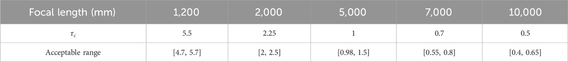
Table 1. Focal length and corresponding τc value.
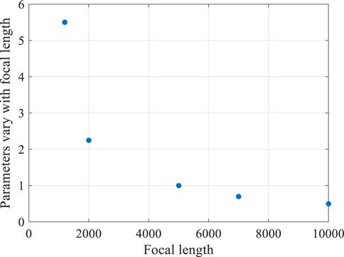
Figure 1. Relationship between focal length and parameters that vary with focal length.
The fitting results are shown in Figure 2. The mean squared errors (MSE) of the fitting are 4.57 × 10⁻2 and 3.59 × 10⁻⁹ for focal lengths less than and greater than 5,000 mm, respectively. The fitted τc values fall within the acceptable range, indicating that the fitting performance is satisfactory. There is a discontinuity at 5,000 mm in the fitting curve, which is attributed to the segmented fitting approach. Since the fitting aim is to establish a simple mapping relationship to calculate the corresponding τc value using a given focal length, rather than generating freeform surfaces or curves, this discontinuity is considered acceptable for real applications. The fitting results indicate that the fit provided by Figure 2B is superior for the focal length of 5,000 mm. Therefore, the fitting formula from Figure 2B (
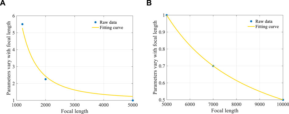
Figure 2. Fitting results. (A) The focal length is less than 5,000 mm. (B) The focal length is larger than 5,000 mm.
Using the matrix method to establish the optical relationship between the mirror distance and curvature radii in a coaxial reflective system,
where
Based on Equation 10, the objective function of curvature radius is obtained as,
where
By substituting dmax and dmin into Equation 11, the corresponding combinations of curvature radii {rDMAX} and {rDMIN} can be obtained. Consequently, the curvature radius search space for each mirror is obtained as,
2.2 Adaptive design of search spaces for tilt angles
When the mirror rotates clockwise, the tilt angle is defined as positive; otherwise, it is negative. For reflective space cameras, the main objective of tilting the primary mirror is to eliminate the obscuration of the incident rays by the secondary mirror. The sign (positive or negative) of the tilt angle does not affect the optical path structure, as illustrated in Figure 3.
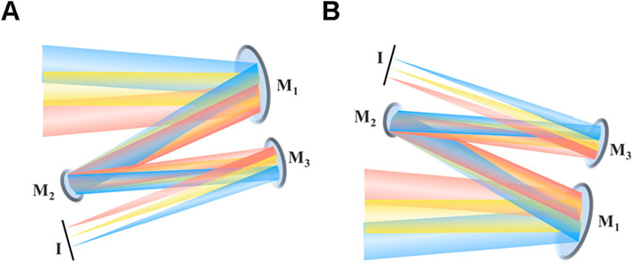
Figure 3. Schematic diagram of the effect of tilt angle of the primary mirror. (A) The tilt angle is negative. (B) The tilt angle is positive.
When the primary mirror’s optical power is negative, it results in a large secondary mirror area, thereby increasing the overall volume of the space camera. This is disadvantageous for creating a lightweight space camera. Therefore, this study limits the primary mirror’s optical power to positive values and constructs the search space for the tilt angle of the primary mirror based on this constraint. The search space for the tilt angle of the primary mirror can be represented in terms of its absolute value as,
where
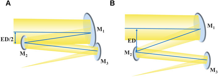
Figure 4. Schematic diagram of the search space for the tilt angle of the primary mirror. (A) The lower limit of the search space. (B) The upper limit of the search space.
The optical path structure is affected by the tilt angle of the secondary mirror. According to the definition of optical path structure in Ref. [32], when the extension line of the incident ray on the secondary mirror (central ray of the center FOV) rotates anti-clockwise, aligning with the outgoing ray at an angle of less than 180°, the rotation vector of the secondary mirror is −1; otherwise, it is 1. Therefore, based on the optical path structure requirements, the search space for the tilt angle of the secondary mirror can be constructed, as shown in Figure 5.
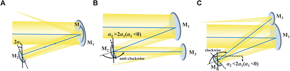
Figure 5. Schematic diagram of the search space for the tilt angle of the secondary mirror. (A) The incident ray on the secondary mirror (central ray of the center FOV) coincides with the outgoing ray. (B) The rotation vector of the secondary mirror is −1. (C) The rotation vector of the secondary mirror is 1.
It can be concluded that when α2 > 2α1, the rotation vector of the secondary mirror is −1; when α2 < 2α1, the rotation vector of the secondary mirror is 1. Simultaneously, to ensure structural compactness, the angle between the incident and outgoing ray is defined as acute angle. Therefore, the search space for the tilt angle of the secondary mirror is derived as,
where
Then, the tilt angle (2 (
where
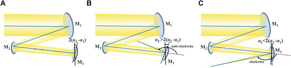
Figure 6. Schematic diagram of the search space for the tilt angle of the tertiary mirror. (A) The incident ray on the tertiary mirror (central ray of the center FOV) coincides with the outgoing ray. (B) The rotation vector of the tertiary mirror is −1. (C) The rotation vector of the tertiary mirror is 1.
2.3 Automatic generation of freeform off-axis reflective space camera
To meet the lightweight requirements, it is necessary to consider the camera size. Based on Snell’s law and the reverse ray tracing method, ray tracing is performed on the central and edge rays of the FOVs of (0,0), (0, FOVy), (0, -FOVy), and (FOVx,0). Subsequently, the coordinates of the intersection points between each ray and the mirror as well as the image plane can be determined, along with the sets of x, y, and z coordinates of all intersection points, denoted as {X}, {Y}, and {Z}. Therefore, the size function of the space camera is given by,
The optical path structure is commonly a key design requirement, so it is essential to represent and assess the optical path of off-axis space cameras. Since the adaptive tilt angle search spaces have already been established based on the design requirements, it is only necessary to evaluate the intersections of the optical paths [32]. The cross function of the optical path is given as,
where
To integrate the primary and tertiary mirrors, it is necessary to ensure that the primary mirror and the tertiary mirror are sufficiently close. Therefore, the primary/tertiary mirror distance discrimination function is defined as,
where
In systems with a z-shaped structure, setting the distance between the primary and secondary mirrors equal to the distance between the secondary and tertiary mirrors can increase the search speed, facilitating rapid convergence towards the goal of integrating the primary and tertiary mirrors. Therefore, when the design requirement of the optical path structure is z-shaped, an additional distances constraint condition needs to be added, that is, |d1| = |d2|.
To ensure that the rays within the system are not obscured by the mirrors or image plane, it is essential to control the off-axis degree. Furthermore, to prevent the risk of obscuration due to surface changes in the subsequent introduction of freeform surfaces, it is necessary to reserve a certain optical margin to address any potential optical path obscuration. And the off-axis degree function is given as,
where OAn is the off-axis degree discrimination number, if the nth mirror does not obscure any rays, OAn = 0, otherwise, OAn equals to the shortest distance from the mirror to the obscured rays; OAMn is the margin discrimination number, if the shortest distance between the nth mirror and any ray in the system is greater than 10 mm, then OAMn = 0. Otherwise, OAMn is the absolute value of the difference between the shortest distance from the mirror to the obscured ray and 10;
To balance the imaging quality of the optical system, it is important to calculate the distances between the imaging positions of rays from different FOVs and the ideal image points. The tilt angle of the ideal image plane is given as,
The coordinates of the ideal image point of the central ray in the central FOV is,
Therefore, the ideal image point coordinates of other FOVs can be calculated [16]. Based on this, the image quality evaluation function is given as,
where K is the total number of sampled rays; i is the sequence number of the sampled rays; (xc,yc,zc) is the coordinate of the ideal image point. It should be noted that since this study evaluates the imaging quality in the global coordinate system, the difference in the z-coordinate also needs to be calculated.
Subsequently, based on Equations 17–23 the structural parameter objective function is established as,
where
By searching for the minimum value of Equation 24, the structural parameters that best meet the design requirements are obtained. Then, the improved W-W method is used to obtain the discrete point combinations of the mirrors [27]. In this study, the Fringe Zernike polynomial is used for fitting, the expression is described as,
where c is the curvature; ρ is the radial height in the polar coordinate system; k is the conic coefficient; j is the serial number of the Zernike term. To avoid surface displacement due to the positional changes and tilts introduced by the first three Fringe Zernike terms, these terms are set to zero; Cj is the coefficient of the jth Zernike term; Zj is the jth Zernike term; Z is the vector height of each point on the surface.
In summary, a designer can easily achieve a long-focal-length freeform off-axis reflective space camera with lightweight and integration of primary/tertiary mirror by only inputting the design requirements. The flow chart of the design method proposed in this study is shown in Figure 7.
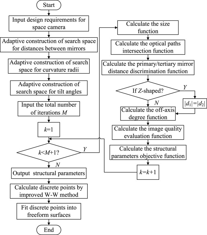
Figure 7. Flow chart of the design method in this study.
3 Experiment
To validate the adaptive design method proposed in this study, two freeform off-axis reflective space cameras with different optical path structures were designed in our experiments. The software used was Matlab R2018b; the optical simulation software used to optimize was Zemax OpticStudio 20.3.2. The computer system was Intel Core i5-11300H @ 3.10 GHz processor.
3.1 Z-shaped space camera
In this experiment, our proposed method was used to design a z-shaped freeform off-axis reflective space camera, the specifications are presented in Table 2. First, τ1 and τ2 were obtained using Equations 3, 4, τ1 = 3.70, τ2 = 2.67. Then, the SA method was used to find out the search spaces for radii of curvature, and Equation 11 was used as the error function. The upper and lower limits of radii of curvature during the searching process, as well as the results, are shown in Table 3. The initial values of searching were randomly generated by MATLAB and Equations 12, 13 were used to set the search spaces for radii of curvature.
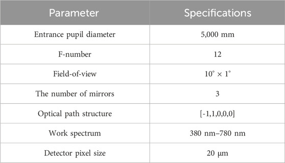
Table 2. Specifications of the z-shaped space camera.
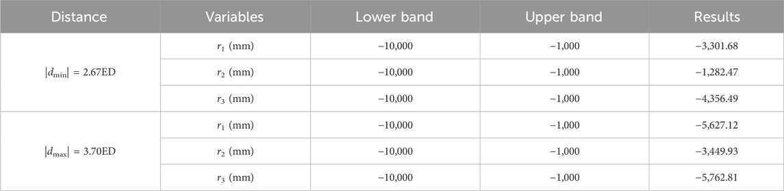
Table 3. The search spaces for the z-shaped space camera.
Subsequently, the search spaces for the tilt angle of the primary mirror was set as α1∈[-11.01, −3.88] according to Equation 14. According to the design requirements, VS = −1 and VT = 1 were obtained. Therefore, the search spaces for the tilt angles of the secondary and tertiary mirrors were calculated based on Equations 15, 16 as α2∈[2α1, α1+π/4] and α3∈[2 (α2-α1)-π/4, 2 (α2-α1)], respectively. Then, the SA method was utilized to search for the structural parameters of the z-shaped space camera. The search spaces and results related to the tilt angles, radii of curvature, and distances between mirrors are listed in the right column of Table 4. The initial temperature was set at 1,500, and Equation 24 was used as the error function, δ1 = 1 × 10⁻⁸, δ2 = δ3 = 50, δ4 = δ5 = 1, σ1 = 5, σ2 = 1, and Q = 100. Figure 8 illustrates the error function’s variation curve throughout the search process. Table 3 and Figure 8 demonstrate that a range of structural parameters can be searched within the search spaces obtained using the proposed method, which validates the rationality of the established search spaces. The error curve starts to stabilize and settles at a steady value of 17.28 after exceeding 90 iterations.
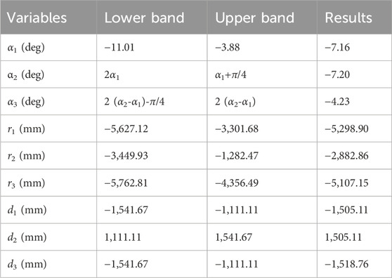
Table 4. The structural parameters for searching the z-shaped space camera.
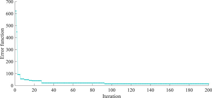
Figure 8. The process of searching for the structural parameters of the z-shaped space camera.
Then, the improved W-W method was employed to design the discrete points of the mirrors, and Equation 25 was used as the fitting function, the obtained freeform off-axis reflective space camera is outlined in Figure 9. It can be observed that the integration of the primary and tertiary mirrors in the designed space camera is effectively combined, with rays from all FOVs converging at the image plane. The RMS spot radius and wavefront of the central FOV are 13.32 μm and 0.10 λ, respectively. This suggests that the freeform off-axis reflective space camera created using the proposed method exhibits suitable structural parameters and optimal imaging performance. To validate the compactness of our designed system, the size of our space camera was calculated using Equation 17, and compared with off-axis three-mirror systems from Refs. [5, 11] that have the same design requirements. The calculation results are presented in Table 5. From Table 5, it is evident that, compared to the off-axis three-mirror system in Ref. [5], which does not consider volume constraints, the space camera designed in this study exhibits a significant reduction in size, which is 1.28 m3. Compared to the system in Ref. [11], which considers volume constraints but does not account for primary/tertiary mirror integration, our system still achieves a reduction in size. This is due to the primary/tertiary mirror integration search criteria used in this study, which reduces the dimensionality of the search spaces.
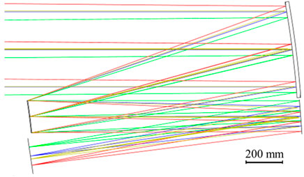
Figure 9. The layout of the z-shaped freeform off-axis reflective space camera.

Table 5. Comparison of size of optical systems.
Finally, to further evaluate the optimization potential of the space camera designed in this study, the Zemax optical software was employed to optimize the system produced by our method. During the optimization process, the mirror positions and tilt angles were not altered; only the coefficients of higher-order terms above z3 for the freeform surfaces were optimized. And it was ensured that the minimum distance between the primary and tertiary mirrors did not exceed 120 mm and that the edge points of the mirrors did not obscure the rays in the space camera. The optimized space camera’s layout, modulation transfer function (MTF) curve, and spot diagram are illustrated in Figure 10. It can be seen that the layout of the optimized space camera remains unchanged from the space camera generated by our method. In the chosen FOVs, the MTF curves are all exceed 0.45 at 50 lp/mm, close to the diffraction limit. Most of the imaging spots are contained within the Airy disk, and its range is from 1.29 to 3.64 µm, which are smaller than the detector pixel size. These results demonstrate that our optimized space camera delivers excellent imaging performance, and the designed space camera has the potential for optimization. Table 6 presents a comparison of the system layout and performance across different stages of the design process, including search, improved W-W design, and final optimization results. Since the positions and tilt angles of the mirrors remained unchanged during both the improved W-W design and final optimization stages, only the surface shapes were modified. Consequently, the minimum distance between the primary and tertiary mirrors was utilized to assess subtle variations in the system layout. Additionally, the RMS spot radius of the central FOV was employed to evaluate system performance. It can be observed that using the search method produces a space camera with a high level of primary and tertiary mirrors integration, but with suboptimal imaging quality. This is because, at this stage, the space camera is an off-axis spherical system and has not yet employed freeform surfaces to correct aberrations. And it is evident that the use of the improved W-W method to generate freeform surfaces significantly enhanced the imaging performance of the system, while the minimum distance between the primary and tertiary mirrors remains relatively stable. Following the final optimization, further improvements in imaging performance are observed, alongside a change in the minimum distance between the primary and tertiary mirrors, yet the space camera maintains a robust integrated structure. This indicates that the structural parameters derived using the method outlined in this study effectively meet the design requirements of optical systems, exhibit high stability, and provide reliable input for subsequent stages, thereby reducing the complexity and difficulty of optimization. This further demonstrates that the method proposed in this study is capable of generating the freeform space camera with a high degree of integration and favorable imaging performance, providing a solid foundation for final optimization efforts.
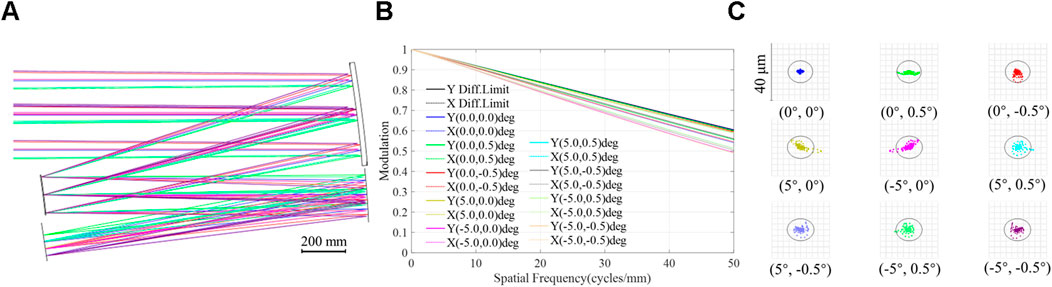
Figure 10. Design results for the z-shaped freeform off-axis reflective space camera after optimization. (A) Layout. (B) MTF curve. (C) Spot diagram.
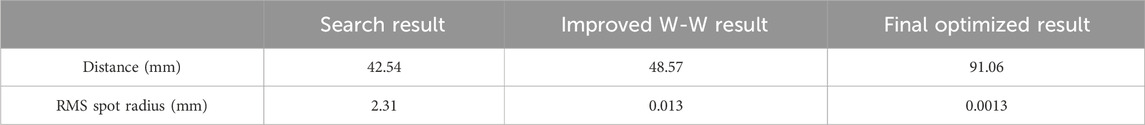
Table 6. Comparison of the integration and performance at different stages.
3.2 Non-z-shaped space camera
To validate the applicability of the proposed method to different structures and focal lengths of space cameras, an off-axis three-mirror space camera with a focal length of 15,000 mm and a non-z-shaped structure was generated using our method. The system specifications are detailed in Table 7.
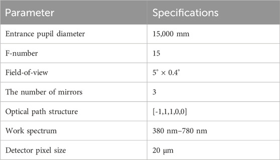
Table 7. Specifications of the non-z-shaped space camera.
First, τc was calculated to be 0.36 using Equation 9, τ1 = 5.26 and τ2 = 2.61 were determined based on Equations 3 and 4. The search spaces for the radii of curvature were determined, and the bounds and final results of the search process are shown in Table 8. The primary mirror was set to rotate clockwise, and the search space for the tilt angle of the primary mirror was defined as α1∈[2.73, 11.28] according to Equation 14. According to the design requirements, VS = −1 and VT = 1, so the search spaces for the tilt angles of the secondary and tertiary mirrors were α2∈[2α1, α1+π/4] and α3∈[2 (α2-α1)-π/4, 2 (α2-α1)], respectively.
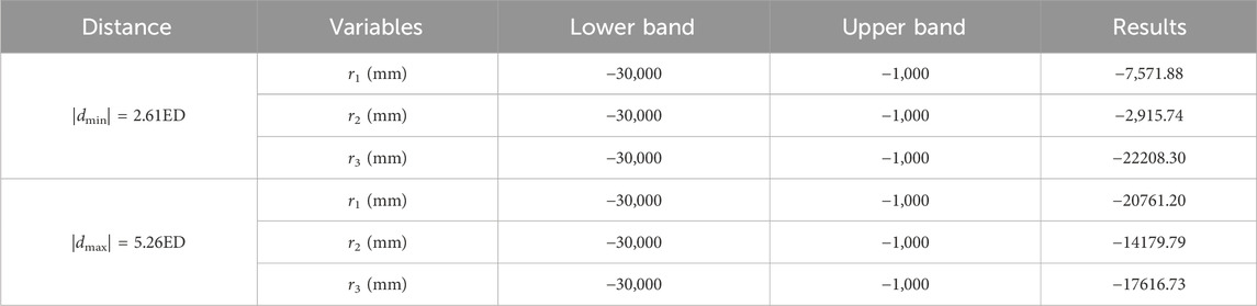
Table 8. The search spaces for the non-z-shaped space camera.
Since the system has a non-z-shaped structure, the condition |d1| = |d2| cannot be employed to reduce the dimensionality of the search spaces. Therefore, a two-stage SA method was utilized. The initial temperature was 1,500, Equation 24 was served as the error function, δ1 = 1 × 10⁻⁹, δ2 = δ3 = 50, δ4 = δ5 = 1, σ1 = 5, σ2 = 1, and Q = 100. In the first-stage search, when the value of the error function remained unchanged for 30 iterations, the corresponding structural parameters were automatically used as the initial values to begin the second-stage search. And the initial values were set to random values in the first-stage search. For the first and second stage searches, the error function curves are shown in Figures 11A, B, respectively. The search spaces and the results of the two-stage search are presented in Table 9. The following conclusions can be drawn from Figure 11 and Table 9.
1) In the first-stage search, when the number of iterations exceeds 70, the error value stabilizes at 146.64 and remains at this value for 30 iterations; In the second-stage search, when the number of iterations exceeds 60, the error value stabilizes at 35.82; After two-stage searching, suitable structural parameters can still be found within a total of 200 iterations.
2) Using the results from Results 1 as the initial values, the error value of the first set of search results in the second-stage search is 156.11. This is because, in the SA method, the initial values serve as reference points. The first set of values in the iterative process is generated based on the initial values, and the error function values corresponding to this new set of values are then computed.
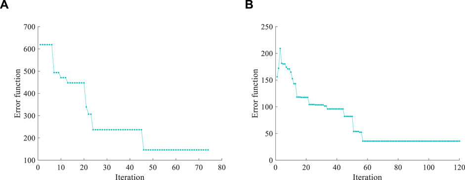
Figure 11. The process of searching for the structural parameters of the non-z-shaped space camera. (A) First-stage search. (B) Second-stage search.
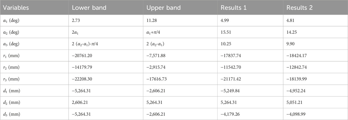
Table 9. The structural parameters for searching the non-z-shaped space camera.
Therefore, the method presented in this study can adaptively generate reasonable search spaces for structural parameters. In the methodology section of this study, multiple systems with a focal length of up to 10,000 mm (as shown in Figure 1) were used to determine the coefficient expressions for the search spaces for distances between mirrors (Equations 1–9). These expressions remain applicable to space cameras with a focal length of 15,000 mm (beyond the fitting range) in this example. Moreover, the radius of curvature and tilt angle search spaces obtained based on the search space are also suitable for this example, further validating the generalization and effectiveness of the proposed method.
After surface fitting with the improved W-W method, an off-axis reflective freeform space camera was designed and the resulting is illustrated in Figure 12. It is apparent that the integration degree of the primary and tertiary mirrors is high. The RMS spot radius and wavefront of the central FOV are 5.18μm and 0.08λ, respectively, quantitatively reflects that the imaging performance is satisfactory. Finally, the Zemax optical software was used to optimize the space camera, and the optimization constraints are consistent with the previous experiment. The layout, MTF curve, and spot diagram of the optimized space camera are illustrated in Figure 13. It can be observed that for rays from different FOVs, the majority of the imaging spots fall within the Airy disk, with radii ranging from 2.72 μm to 4.67μm, all of which are smaller than the pixel size; the MTF curves are all exceed 0.4 at 50 lp/mm. These experimental results prove that the designed space camera has the potential for optimization, and effectively ensures high imaging quality, lightweight, and ease of manufacturing. And Table 10 presents the comparison of the system layout and performance at different stages of the design process. Data from various design stages indicate that the minimum distance between the primary and tertiary mirrors exhibits limited variation, demonstrating a high level of integration in the space camera. For the non-z-shaped space camera in this experiment, the method proposed in this study still achieves a high degree of integration and satisfactory imaging performance. This proves that the design method presented in this study can provide a reasonable search space for structural parameters of long-focal-length space cameras tailored to different design requirements, and yield stable structural parameters. These parameters do not require further optimization in subsequent processes and provide a sound basis for the generation and optimization of freeform surfaces. Designers need only perform simple surface shape optimization on the freeform space camera generated using the method described in this study to achieve a space camera approaching the diffraction limit.
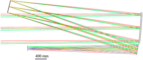
Figure 12. The layout of the non-z-shaped freeform off-axis reflective space camera.
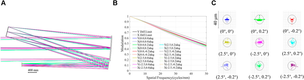
Figure 13. Design results for the non-z-shaped freeform off-axis reflective space camera after optimization. (A) Layout. (B) MTF curve. (C) Spot diagram.
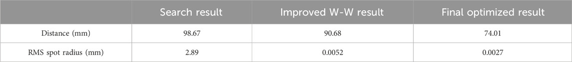
Table 10. Comparison of the integration and performance at different stages.
4 Conclusion
In this study, an adaptive design of long-focal-length freeform off-axis reflective space cameras with lightweight and integration of primary/tertiary mirror is proposed, which is effective to adaptively generate freeform off-axis spatial cameras that satisfy multiple constraints based on design and manufacturing requirements. First, a method to adaptively define the search spaces of structural parameters is developed. This method is applicable to long-focal-length off-axis space cameras of various specifications and can flexibly generate corresponding tilt angle search spaces based on different optical path structure requirements. Subsequently, a structural parameter objective function is constructed based on the requirements for lightweight, ease manufacturability and high imaging quality. Finally, using the structural parameters obtained from the search as inputs, the improved W-W method is employed to automatically generate the freeform off-axis space camera. Results from two sets of experiments indicate that the structural parameters can be identified within 200 iterations using the method proposed in this study, even addressing different design requirements. Additionally, reasonable inputs for the improved W-W method can be provided, leading to the adaptive generation of a freeform off-axis reflective space camera. In future research, we will consider appropriate improvements to the SA algorithm to further reduce the number of iterations required for the search.
Data availability statement
The original contributions presented in the study are included in the article/supplementary material, further inquiries can be directed to the corresponding author.
Author contributions
YS: Methodology, Software, Writing–original draft. YW: Funding acquisition, Supervision, Writing–review and editing. JZ: Funding acquisition, Writing–review and editing.
Funding
The author(s) declare that financial support was received for the research, authorship, and/or publication of this article. This research was financially supported by the National Natural Science Foundation of China (no. 62373084).
Conflict of interest
The authors declare that the research was conducted in the absence of any commercial or financial relationships that could be construed as a potential conflict of interest.
Publisher’s note
All claims expressed in this article are solely those of the authors and do not necessarily represent those of their affiliated organizations, or those of the publisher, the editors and the reviewers. Any product that may be evaluated in this article, or claim that may be made by its manufacturer, is not guaranteed or endorsed by the publisher.
References
1. Meng Q, Wang D, Wang X, Li W, Yang X, Yan D, et al. High resolution imaging camera (HiRIC) on China’s first mars exploration tianwen-1 mission. Space Sci Rev (2021) 217:42. doi:10.1007/s11214-021-00823-w
2. Han L, Mao B, Sun W, Shen W. Analysis and design of coaxial three-mirror anastigmat with long effective focal length and full two-dimensional field. In: 8th international symposium on advanced optical manufacturing and testing technologies: large mirrors and telescopes (SPIE). Suzhou, China (2016). p. 96820E. doi:10.1117/12.2241619
3. Chang S, Lin Y, Lien C, Huang T, Teay H, Miau J. The design and assembly of a long-focal-length telescope with aluminum mirrors. In: International conference on space optics — ICSO 2018 (spie). Chania, Greece (2018). p. 9–12. doi:10.1117/12.2536165
4. Bai X, Xu B, Ju G, Ma H, Zhang C, Wang S, et al. Aberration compensation strategy for the radius of curvature error of the primary mirror in off-axis three-mirror anastigmatic telescopes. Appl Opt (2021) 60:6199–212. doi:10.1364/AO.431908
5. Wang L, Fan X, Ni D, Wang Y. Optical design of off-Axis three-mirror system with long-focal-length and wide FOV. In: 9th international symposium on advanced optical manufacturing and testing technologies: large mirrors and telescopes (SPIE). Chengdu, China (2018). p. 26–9. doi:10.1117/12.2504962
6. Mao B, Yang T, Xu H, Chen W, Cheng D, Wang Y. FreeformNet: fast and automatic generation of multiple-solution freeform imaging systems enabled by deep learning. Photon Res (2023) 11:1408–22. doi:10.1364/PRJ.492938
7. Chen W, Yang T, Cheng D, Wang Y. Generating starting points for designing freeform imaging optical systems based on deep learning. Opt Express (2021) 29:27845–70. doi:10.1364/OE.432745
8. Bauer A, Schiesser EM, Rolland JP. Starting geometry creation and design method for freeform optics. Nat Commun (2018) 9:1756. doi:10.1038/s41467-018-04186-9
9. Nie Y, Zhang J, Su R, Ottevaere H. Freeform optical system design with differentiable three-dimensional ray tracing and unsupervised learning. Opt Express (2023) 31:7450–65. doi:10.1364/OE.484531
10. Yan Q, Wan Z, Yang C. Flight load calculation using neural network residual kriging. Aerospace (2023) 10:599. doi:10.3390/aerospace10070599
11. Sun Y, Wei Y, Di X, Zhao J. Automatic generation method for long-focal-length unobscured freeform optical systems with small volume. Appl Opt (2024) 63:3702–11. doi:10.1364/AO.524442
12. Li Z, Liu X, Fang F, Zhang X, Zeng Z, Zhu L, et al. Integrated manufacture of a freeform off-axis multi-reflective imaging system without optical alignment. Opt Express (2018) 26:7625–37. doi:10.1364/OE.26.007625
13. Li Z, Fang F, Chen J, Zhang X. Machining approach of freeform optics on infrared materials via ultra-precision turning. Opt Express (2017) 25:2051–62. doi:10.1364/OE.25.002051
14. Rolland JP, Davies M, Suleski T, Evans C, Bauer A, Lambropoulos J, et al. Freeform optics for imaging. Optica (2021) 8:161–76. doi:10.1364/OPTICA.413762
15. Zhu J, Hou W, Zhang X, Jin G. Design of a low F-number freeform off-axis three-mirror system with rectangular field-of-view. J Opt (2015) 17:015605. doi:10.1088/2040-8978/17/1/015605
16. Yang T, Zhu J, Jin G. Compact freeform off-axis three-mirror imaging system based on the integration of primary and tertiary mirrors on one single surface. Chin Opt Lett (2016) 14:060801–5. doi:10.3788/COL201614.060801
17. Meng Q, Wang H, Wang K, Wang Y, Ji Z, Wang D. Off-axis three-mirror freeform telescope with a large linear field of view based on an integration mirror. Appl Opt (2016) 55:8962–70. doi:10.1364/AO.55.008962
18. Sun Y, Sun Y, Chen X, Wang F, Yan X, Zhang X, et al. Free-form off-axis three-mirror optical antenna design with an integrated primary/tertiary-mirror structure. Appl Opt (2021) 60:10132–9. doi:10.1364/AO.437587
19. Miñano J, Benítez P, Narasimhan B. Freeform aplanatic systems as a limiting case of SMS. Opt Express (2016) 24:13173–8. doi:10.1364/OE.24.013173
20. Nie Y, Mohedano R, Benítez P, Chaves J, Miñano J, Hugo T, et al. Multifield direct design method for ultrashort throw ratio projection optics with two tailored mirrors. Appl Opt (2016) 55:3794–800. doi:10.1364/AO.55.003794
21. Yang T, Jin G, Zhu J. Automated design of freeform imaging systems. Sci Appl (2017) 6:e17081. doi:10.1038/lsa.2017.81
22. Yang T, Zhu J, Wu X, Jin G. Direct design of freeform surfaces and freeform imaging systems with a point-by-point three-dimensional construction-iteration method. Opt Express (2015) 23:10233–46. doi:10.1364/OE.23.010233
23. Zhang B, Jin G, Zhu J. Towards automatic freeform optics design: coarse and fine search of the three-mirror solution space. Light: Sci Appl (2021) 10:65. doi:10.1038/s41377-021-00510-z
24. Yang T, Cheng D, Wang Y. Freeform imaging spectrometer design using a point-by-point design method. Appl Opt (2018) 57:4718–27. doi:10.1364/AO.57.004718
25. Volatier J, Druart G. Differential method for freeform optics applied to two-mirror off-axis telescope design. Opt Lett (2019) 44:1174–7. doi:10.1364/OL.44.001174
26. Cheng D, Wang Y, Hua H. Freeform optical system design with differential equations. In: Optical design and testing IV (SPIE). Beijing, China (2010). p. 78490Q. doi:10.1117/12.869690
27. Chen S, Wei Y, Sun Y, Li B, Zhao J. Off-axis three-mirror freeform systems design based on improved W-W differential equations. Appl Opt (2023) 62:3892–903. doi:10.1364/AO.483753
28. Sun Y, Sun Y, Chen X, Wang F, Yan X, Zhang X, et al. Design of a free-form off-axis three-mirror optical system with a low f-number based on the same substrate. Appl Opt (2022) 60:7033–10139. doi:10.1364/AO.457646
29. Sun Y, Wei Y, Chen S, Zhao J. Fast starting point generation method for unobscured two-mirror imaging systems with large field-of-views. Optik (2023) 288:171159. doi:10.1016/j.ijleo.2023.171159
30. Cao C, Liao S, Liao Z, Bai Y, Fan Z. Initial configuration design method for off-axis reflective optical systems using nodal aberration theory and genetic algorithm. Opt Eng (2019) 58:105101. doi:10.1117/1.OE.58.10.105101
31. Yu X, Wang H, Yao Y, Tan S, Xu Y, Ding Y. Automatic design of a mid-wavelength infrared dual-conjugate zoom system based on particle swarm optimization. Opt Express (2021) 29:14868–82. doi:10.1364/OE.418584
Keywords: space camera, freeform, long-focal-length, lightweight, integration
Citation: Sun Y, Wei Y and Zhao J (2024) Adaptive design of long-focal-length freeform off-axis reflective space cameras with lightweight and integration of primary/tertiary mirror. Front. Phys. 12:1481131. doi: 10.3389/fphy.2024.1481131
Received: 15 August 2024; Accepted: 12 September 2024;
Published: 27 September 2024.
Edited by:
Tong Yang, Beijing Institute of Technology, ChinaReviewed by:
Chen Xu, Hangzhou Dianzi University, ChinaGiuseppe Brunetti, Politecnico di Bari, Italy
Copyright © 2024 Sun, Wei and Zhao. This is an open-access article distributed under the terms of the Creative Commons Attribution License (CC BY). The use, distribution or reproduction in other forums is permitted, provided the original author(s) and the copyright owner(s) are credited and that the original publication in this journal is cited, in accordance with accepted academic practice. No use, distribution or reproduction is permitted which does not comply with these terms.
*Correspondence: Yangjie Wei, d2VpeWFuZ2ppZUBjc2UubmV1LmVkdS5jbg==