 Qiuyue Nie
 Guoqiang Wei
 Zhonglin Zhang
 Zelin Zhang2
- 1School of Physics, Harbin Institute of Technology, Harbin, China
- 2School of Electrical Engineering and Automation, Harbin Institute of Technology, Harbin, China
- 3Laboratory for Space Environment and Physical Science, Harbin Institute of Technology, Harbin, China
Manipulating electromagnetic (EM) waves by plasma–dielectric–plasma (PDP) waveguides or plasma array structures presents significant potential in microwave signal processing, such as filtering, signal delay, and EM enhancement or shielding. Owing to the simple structure and easy fabrication, the waveguide with a tooth-shaped resonator has been a strong candidate as a filtering device. Based on our previous work focusing on U-shaped filtering excited by PDP waveguides with a double-teeth structure, in this work, the formation mechanism of a U-shape filtering spectrum is systematically explored by transmission line theory (TLT) with proper field distributions. The results indicate that the U-shape spectrum consists of boundary edges and a filtering stopband. The boundary edges are attributed to Fano-type resonance, and the enhanced destructive interference from double teeth is responsible for the stopband. Such an approach shows a specific and clear mechanism for the generated U-shaped spectrum. In addition, the theoretical analysis of double teeth without Fano-type resonances is rigorously demonstrated using TLT, which significantly contributes to bandwidth modulation of stopband filtering in theory. These results contribute to the understanding of the formation mechanism of a U-shaped spectrum from a gap plasmon waveguide (such as PDP or metal–insulator–metal (MIM)) with tooth-shaped resonators, offering a feasible direction for the optimization of filtering properties, as well as offering significant parameters for subsequent experimental design.
1 Introduction
Planar waveguides (i.e., slab waveguides) can effectively confine electromagnetic (EM) waves in a planned path. To meet specific EM application scenarios, all types of resonators are suitably located around and in slab waveguides (e.g., EM waves in resonators can be coupled with ones in slab waveguides). With appropriate locations, numerous physics phenomena, such as resonance with different modes [1–3], Fano resonance [4, 5], and plasmon-induced transparency (PIT) [6, 7], can be generated and further applied in many fields, including filtering, slow light, switches, and sensors. For traditional planar waveguides, a remarkable diffraction limit affected by waveguide sizes will greatly constrain the miniaturization of EM devices. However, for modern informatization, the size of EM devices is a key to meeting the demand for highly integrated technology. Therefore, researchers have devoted to developing specific slab waveguides to overcome the diffraction limit. By exciting surface plasmon polaritons (SPPs) in specially designed slab waveguides, EM waves can propagate along the metal–insulator (or plasma–dielectric, etc.) interface to break the diffraction limit constraint. The metal, plasma, graphene, and Dirac semi-metal are several typical materials to constitute SPP waveguides. Moreover, according to the similarity principle of the Maxwell equations, the SPP theory can be regulated by the slab waveguides to be applied in different EM bands. Thus, those materials can be commonly used in near-infrared, microwave, and terahertz bands.
In slab waveguides, tooth structures are the most basic construction to control SPP propagation. As a typical application in near-infrared bands, transmission properties of tooth structures in metal–insulator–metal (MIM) waveguides have been widely investigated [8–25]. For a single tooth [8, 9], its transmission spectrum has a symmetric Lorentzian profile with resonant valleys. The generation mechanism of transmission valleys is clear, and the conventional theory can estimate their positions. For the double teeth, on the other hand, the transmission spectrum generally features a typical U-shape. Due to the property suitable for stopband filtering, many efforts have been made to understand the formation mechanism and calculate the U-shaped spectrum with different parameters. For example, for the tooth structures in MIM waveguides, analytical expressions of transmission responses have been obtained via transmission line theory (TLT), with the terms in expressions of clear physics significance [10]. However, conclusions have been drawn by comparing the expressions of single and double teeth with a not rigorously derived term for multipath interference between waves reflected by stubs. On the other hand, further studies have revealed that the bandgap of the U-shaped spectrum is attributed to the multiple superpositions of the destructive interference of each tooth [11, 12].
Because of the typical U-shaped profile suitable for stopband filtering, a certain analogy of the double teeth configuration in MIM waveguides [16–21], such as trapezoid, hexagon [21], T-shaped resonator [17], teeth with defects [19], and aperture-coupled square cavities [18], has been widely proposed and investigated, whereas simulation results tend to focus on the performance optimization of the filter and discussions of filtering change, nevertheless without a deeper analysis of the U-shaped spectrum. In other words, the formation mechanism of the U-shaped profile has been neglected previously in systematical studies, especially quantitative analysis.
As a controllable EM medium, plasma plays a significant role in developing tunable and reconfigurable microwave devices. Compared with relatively complex plasma array structures [26–29], PDP waveguides have a simple structure to control some behaviors (i.e., transmission, reflection, and absorption) of EM waves. Different from similar MIM waveguides in the optical band, the SPPs’ behaviors manipulated by PDP waveguides in the microwave regime are flexibly tunable by altering the plasma electron density. Our previous work has demonstrated that a PDP waveguide with double-teeth resonators could excite a typical U-shaped filtering spectrum [30], and its focus is to investigate filtering change rules at different structure sizes and plasma frequencies. However, its generation mechanism has not been systematically explored. In this work, TLT is introduced to verify the validity of numerical results and to quantitatively analyze the U-shaped spectrum. The U-shaped spectrum is made of two parts, boundary edges and a stopband. By our simulation results, the generation process of the two parts can be discussed in detail via field distributions and TLT. The rest of this paper is structured as follows. Section 2 illustrates the schematic diagram of the PDP waveguide with tooth resonators and the corresponding circuit model of TLT, simulation parameters, and formula derivation. Section 3 consists of two parts: first, the generation process of the U-shaped spectrum. The second part shows that the generation mechanism of the U-shaped spectrum is equally applicable to the analysis of the one with different geometrical parameters. Section 4 draws the conclusion.
2 Waveguide structures and theory analysis
On the basis of our previous PDP waveguide models [30], considering different height combinations, the two-dimensional (2D) schematic of the PDP waveguide with a double-teeth structure is displayed in Figure 1A, where the blue region represents dielectric SiO2 with εd = 2.1, enclosed by gaseous discharge plasmas marked in purple. In a convenient approximation, the plasma can be treated as a special EM medium for the wave–plasma interaction. The Drude model is thus widely applied for analyzing the propagation of EM waves in plasmas [31–34]. For simplicity, we regard the plasma as a bulk dielectric medium approximately in a uniform state. Therefore, in our study, plasma permittivity is given by
where
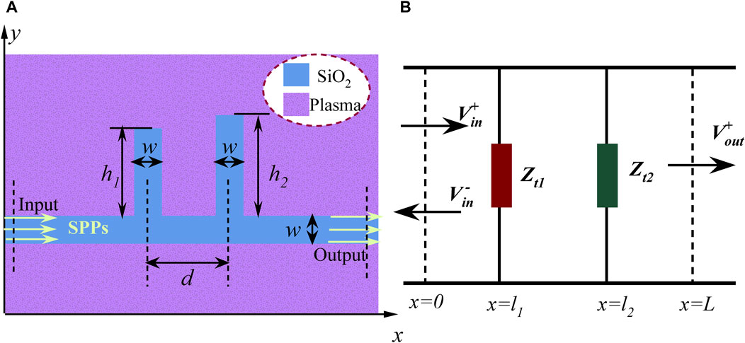
Figure 1. (A) Two-dimensional schematic of a PDP waveguide with a double-teeth cavity. (B) Simplified circuit model in TLT.
In results and discussions, the transmission, obtained via the RF module of COMSOL software, is the ratio of the collected SPPs’ power at the output port to the initial SPPs’ power at the input port. With no specific statement, the numerical simulation parameters are the same as those in Table 1. A more detailed introduction to the model can be found in our previous work [30]. In the experimental design of the interaction between gas plasmas and EM waves, an artificial gaseous plasma environment, confined in a quartz shell, usually can be generated by all types of discharge ways (i.e., ICP, CCP, or DC discharge). The designed SiO2 structure is immersed into an artificial plasma environment to construct PDP waveguides. Moreover, antennas to excite and receive EM signals can be located in two ends of the straight waveguide to obtain S21. The transmission coefficient S21 (|S21|2 is calculated in our simulations) can be obtained by the vector network analyzer. The electron density can be estimated by optical emission spectroscopy and Langmuir probe diagnostics [26].
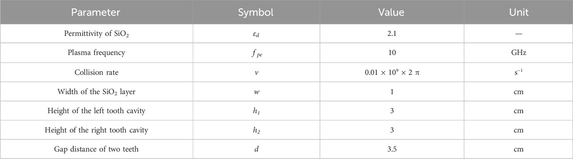
Table 1. Detailed simulation parameters.
In a coupled-resonator waveguide system, the resonance frequencies exhibited in the transmission spectrum usually depend on certain resonance modes in the resonator. According to the standing wave theory, the resonant wavelength of a tooth cavity can be determined as [9, 12]
Different from tooth cavities, rectangular cavities with a narrow width have two reflection interfaces, and their resonant wavelength can be calculated as [4, 35]
Here,
TLT is a theoretical approach combining circuit and field treatments. According to TLT [8, 10, 38], the PDP waveguide with single-tooth structures can be equivalent to a circuit model (as shown in Figure 2). In this paper, we set the plane close to the input port x = 0, the one near the output port x = L, and the centerline of the tooth cavity x = l.
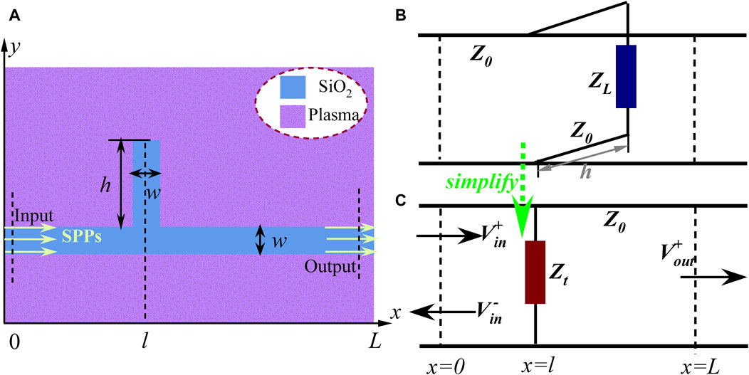
Figure 2. (A) Two-dimensional schematic of a PDP waveguide with a single-tooth cavity. (B) Equivalent circuit model related to the single-tooth structure. (C) Simplified circuit model.
Combining the corresponding circuit model in Figure 2B and TLT, the equivalent impedance of the tooth cavity with height h is written as
The transmission of the circuit model is readily obtained by the transfer matrix method, with
where T is obtained by
Combining Equations 5–7, the transmission of the PDP waveguide with a single-tooth structure is acquired
where
By comparing TS and Td, it can be inferred that, on the right side of the equation, the first term in the modulus factor is the accumulation of the independent filtering response of each tooth cavity, while the second properly indicates interference between two tooth cavities due to factor d. To further understand the above argument, we deduct the result of the double-teeth structure when the SPP interference between double-teeth cavities is ignored. As shown in Figure 3, we split the overall circuit model in Figure 1B into two individual units connected by a gray shadow area. Corresponding to the SPP propagation process, the incident voltage wave
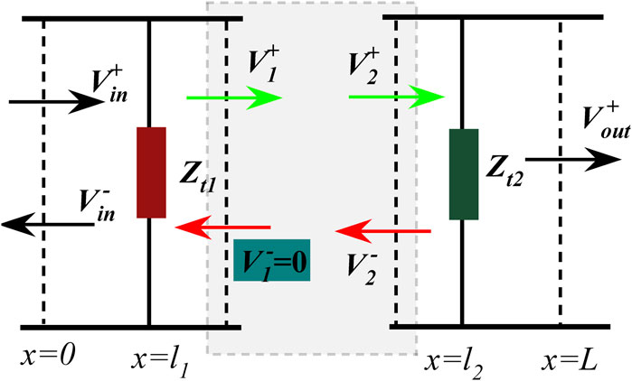
Figure 3. Simplified split circuit model of Figure 1B, to obtain the transmission by ignoring the SPP interference.
Here, Ts1 and Ts2 refer to the transmission of a single left or right tooth, respectively, as displayed in the insets of Figure 5. Apparently, ignoring the SPP interference between double-teeth constructions (i.e.,
3 Results and discussions
3.1 The formation mechanism of a U-shaped spectrum
To demonstrate the validity of TLT, the comparison of transmission responses, with the calculated model indicated by two structure insets, is given in Figure 4. The red dotted lines are the results of TLT obtained by Equations 8, 9, and the black curves are numerical simulations from COMSOL. Clearly, the TLT result exhibits a strong alignment with that of numerical simulations. However, there exists some insignificnat unconformity in spectra, probably due to the approximation used in Equation 4. For the single-tooth structure, its transmission spectrum typically shows a symmetric Lorentz line shape with transmission dips. It is evident that the transmission curve in Figure 4A conforms to this characteristic. The transmission dip observed at 1.04 GHz can be elucidated by the distribution of the magnetic field component Hz. Its emergence is attributed to the destructive interference of two distinct paths of SPPs at the junction of the tooth cavity and the straight waveguide. One path involves the SPP propagation along the straight waveguide, while the other involves the SPP reflection by the end of the tooth cavity. When destructive interference occurs at the junction, there is a resonance in the tooth cavity. According to Equation 2, the theoretically obtained frequency of the dip is approximately 1.22 GHz with neglecting the phase effect of
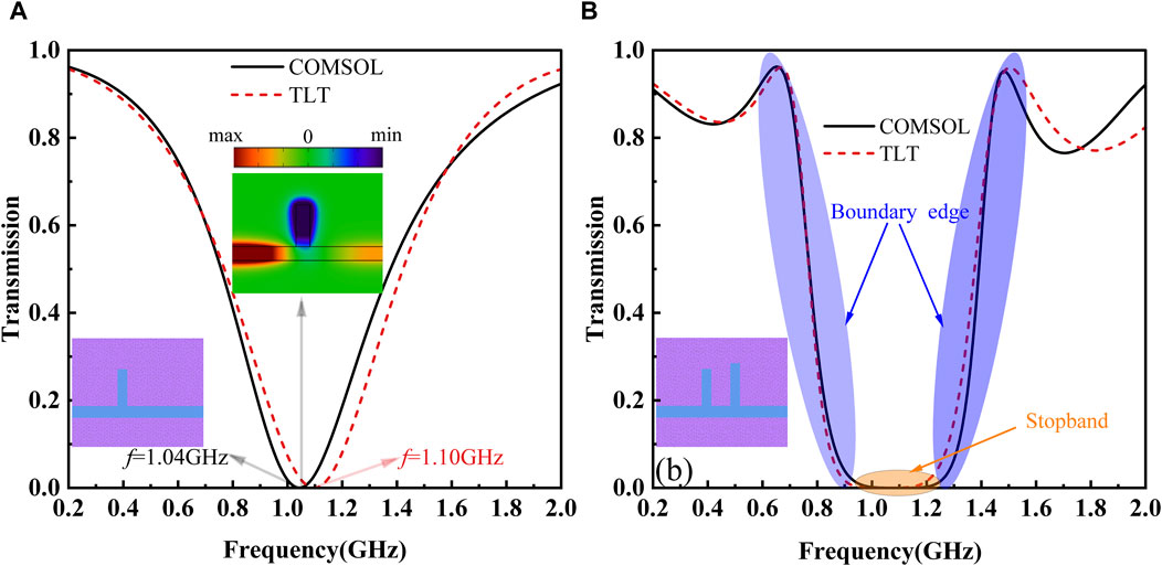
Figure 4. Comparison of transmission responses between COMSOL and TLT. (A) Transmission spectrum of a single-tooth structure, with the inset for the magnetic field distribution in the z-direction at 1.04 GHz. (B) Transmission spectrum for the double-teeth structure.
For the formation mechanism of the stopband, typically there are two types of descriptions in the literature [11, 12, 30]. One attributes to the “enhanced” destructive interference, due to the cumulative effect of the interference from each tooth when SPP waves successively propagate through it. The other, however, suggests the “superposed” destructive interference as SPP waves propagate through both teeth and thus resulting in a stopband. However, these explanations only provide mostly qualitative analysis or quantitative explanation by phase accumulation. For a quantitative explanation by the spectrum evolution process, corresponding simulation results are drawn in Figure 5, where A and B present the transmission responses from the left and right tooth structures, respectively. Based on Equation 8, we can deduce that the transmission of a single tooth is independent of the tooth position. The identical transmission spectrum observed in Figures 5A, B confirms this conclusion. Gray shadow areas in Figures 5A, B are “resonance regions” with a specific resonance width, i.e., the frequency range by 0.1 transmission. Theoretically, the filtering bandwidth of the U-shaped spectrum is equivalent to the resonance width observed in the resonance region when
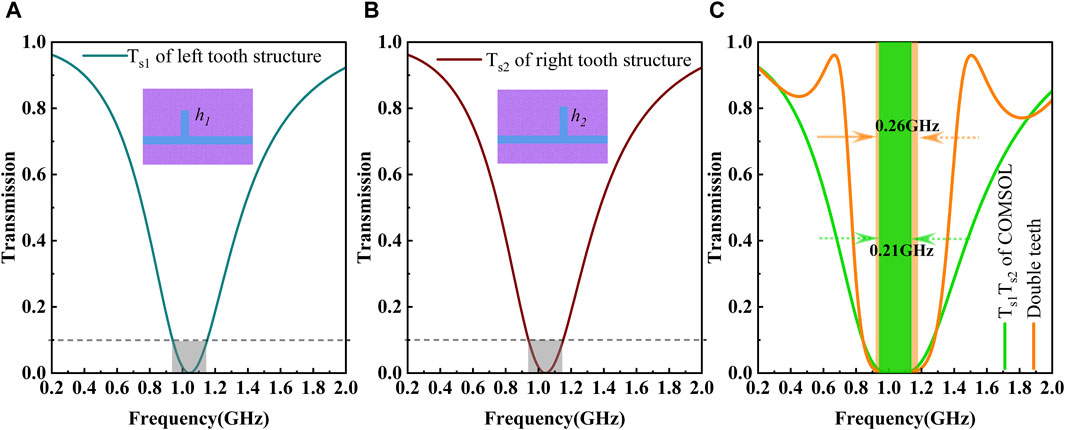
Figure 5. Transmission spectra with different waveguide structures and the product of Ts1 and Ts2. (A) Transmission spectrum of the left tooth structure. (B) Transmission spectrum of the right tooth structure. (C) Green curve for the transmission spectrum obtained by the product of Ts1 and Ts2 and orange curve for that in Figure 4B.
For the boundary edges, the spectrum response is viewed as Fano-like resonances, which exhibits a distinctively sharp and asymmetric profile. This phenomenon is commonly observed in MIM waveguides. Certain studies have illustrated that the discrete states in Fano-like resonance were constructed by the double teeth and their joint [22]. However, the formation process of Fano-like resonances lacks detailed discussion. As depicted in Figure 6, the formation elements, including specific continuous and discrete states, of the boundary edges are provided. Without considering SPPs’ interference between double teeth connected by the PDP channel with length d, the calculated result is presented in Figure 6A, which is the redrawn spectrum from the green curve in Figure 5C. It is evident from the blue curve in Figure 6A that there is a stopband along with two edges displaying monotonic change. The curve presents a wider full width at half maximum (FWHM), which is typically associated with a continuous state. For a more graphic description, the continuous state also is termed as a background spectrum. Discrete states are also an indispensable element in generating Fano-like resonances under appropriate interference conditions. Our study also assumes that the equivalent FP cavity (i.e., FP-like cavity) consists of double teeth and their connecting PDP waveguide. Additionally, the equivalent length of the FP-like cavity is approximately
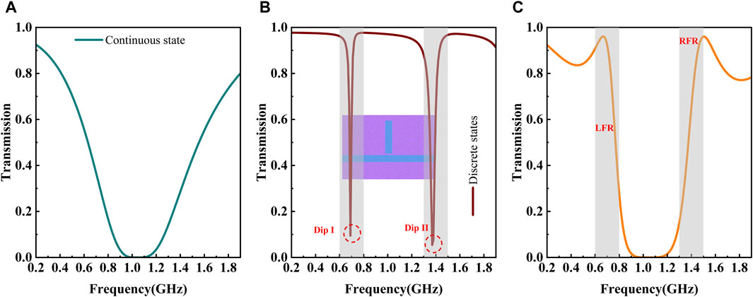
Figure 6. Transmission spectra with different waveguide structures and the product of Ts1 and Ts2. (A) Redrawn transmission spectrum for the green curve in Figure 5C. (B) Transmission spectrum of the FP cavity coupled to the straight PDP waveguide indicated by the inset. (C) Redrawn curve for that in Figure 4B.
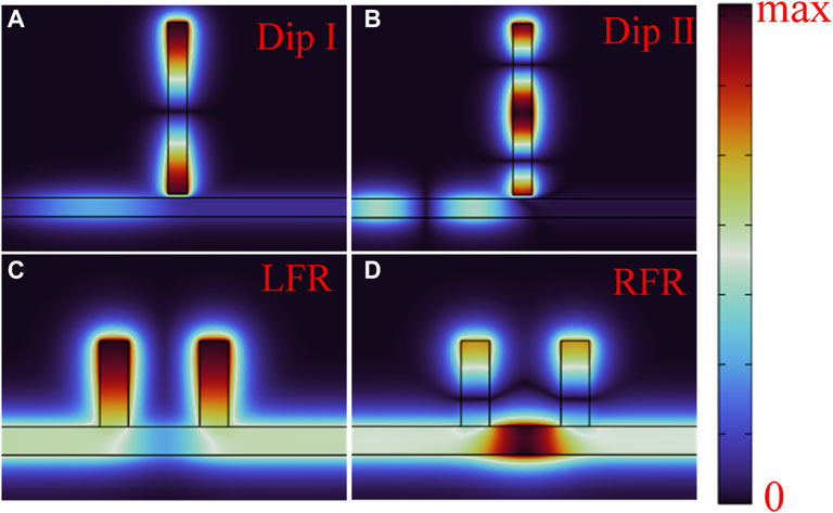
Figure 7. Magnetic field intensity in the z-direction corresponding to Figure 6. (A–D) are field distributions at Dip I, Dip II, LFR and RFR, respectively.
3.2 The modulation of the U-shaped spectrum
To fully verify the rationality of the formation mechanism of a U-shaped spectrum, we will give parameter scan calculations focusing on two aspects: boundary edges and stopband. As mentioned in Section 3.1, the positions of boundary edges primarily depend on the equivalent length of the FP-like cavity
At first, assuming that
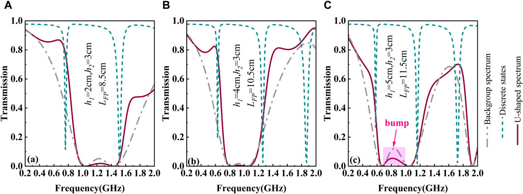
Figure 8. Transmission spectra with different
When
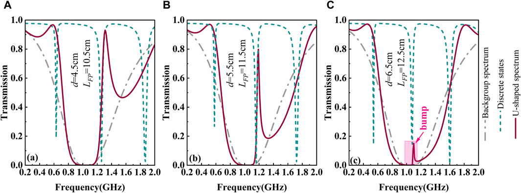
Figure 9. Transmission spectra with different
For the U-shaped spectrum, the bump can greatly affect the filtering function. Therefore, the parameters,
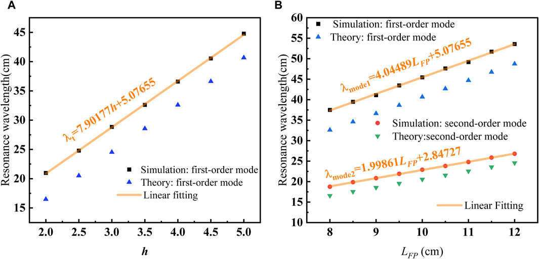
Figure 10. For different structures, a comparison of resonance wavelengths between standing theory and simulation and linear fitting of simulation results. (A) Single-tooth structure in Figure 2A. (B) Structure indicated by the inset in Figure 6B.
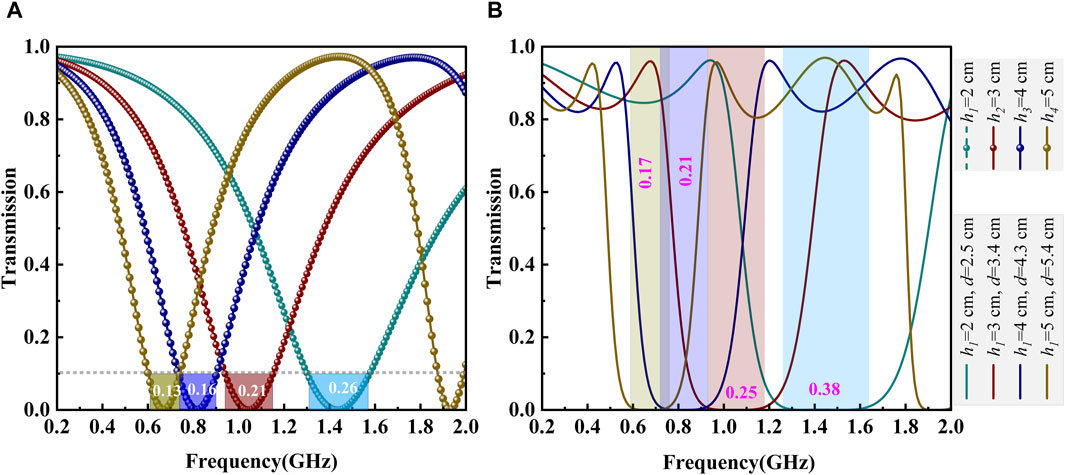
Figure 11. Transmission spectra with different structures and geometrical parameters. The parameters are shown in legend. (A) Single-tooth structure in Figure 2A, and the numbers attached to the color-transparence area represents the resonance width. (B) Double-teeth structure in Figure 1A, and the numbers attached to the color-transparence area are the filtering bandwidth.
4 Conclusion
In summary, based on our previous work focusing on filtering rules, the formation mechanism of the U-shaped spectrum excited by the PDP waveguide with a double-teeth structure is systematically investigated. The transmission responses of the waveguide with a tooth-shaped structure are investigated via numerical simulation and TLT. The simulation demonstrates that the presence of double teeth can induce a U-shaped spectrum, aligning well with the trends observed in TLT. To clarify its formation mechanism, the typical U-shaped spectrum is split into two parts: stopband and boundary edges. The stopband is attributed to the accumulation of destructive interference from each tooth, and its generated spectrum is theoretically derived via TLT and numerically demonstrated via a combination of spectra from independent tooth. Regarding the boundary edges, their formation is caused by Fano-like resonances. The coupling and interference between discrete states and a continuous state result in Fano-like resonances. The discrete states are provided by resonance modes of the equivalent FP cavity, i.e., the combination of double teeth and their connection PDP channel. The background spectrum by a combination of spectra from independent tooth can be regarded as the continuous state. In addition, the evolution process of the U-shaped spectrum is systematically explored, further demonstrating the validity of the generation mechanism. Especially in the evolution process, the bump may emerge around the stopband, which affects the filtering function greatly. At last, based on the parameter settings derived from standing theory prediction, numerical simulations have successfully observed a U-shaped spectrum with a quasi-symmetric profile. Our systematic and in-depth results contribute to understanding the evolution process of complicated spectra from double-teeth constructions, and provide feasible theory guidance in designing simple stopband filters.
Data availability statement
The original contributions presented in the study are included in the article/Supplementary Material; further inquiries can be directed to the corresponding author.
Author contributions
QN: conceptualization, data curation, formal analysis, funding acquisition, investigation, methodology, supervision, validation, writing–review and editing, and writing–original draft. GW: conceptualization, data curation, formal analysis, investigation, methodology, validation, visualization, writing–original draft, and writing–review and editing. ZhZ: formal analysis, investigation, resources, software, and writing–review and editing. ZeZ: formal analysis, investigation, and writing–review and editing. PC: formal analysis, investigation, and writing–review and editing. XA: formal analysis, investigation, and writing–review and editing. LQ: investigation, methodology, and writing–review and editing. CY: formal analysis, investigation, and writing–review and editing.
Funding
The author(s) declare that financial support was received for the research, authorship, and/or publication of this article. This work was supported by the National Natural Science Foundation of China (Nos 92271202 and 92371105).
Conflict of interest
The authors declare that the research was conducted in the absence of any commercial or financial relationships that could be construed as a potential conflict of interest.
Publisher’s note
All claims expressed in this article are solely those of the authors and do not necessarily represent those of their affiliated organizations, or those of the publisher, the editors, and the reviewers. Any product that may be evaluated in this article, or claim that may be made by its manufacturer, is not guaranteed or endorsed by the publisher.
References
1. Faghani AA, Rafiee Z, Amanzadeh H, Yaghoubi E, Yaghoubi E. Tunable band-pass plasmonic filter and wavelength triple-channel demultiplexer based on square nanodisk resonator in MIM waveguide. Optik (2022) 257:168824. doi:10.1016/j.ijleo.2022.168824
2. El Haffar R, Farkhsi A, Mahboub O. Optical properties of MIM plasmonic waveguide with an elliptical cavity resonator. Appl Phys A-mater (2020) 126:486. doi:10.1007/s00339-020-03660-w
3. Keshizadeh H, Aghaei F, Bahador H, Heidarzadeh H. Improvement of cavity plasmon resonance in high-sensitivity MIM nanostructure with rectangular air stubs inside the hexagonal-ring resonator. Phys Scripta (2023) 98:025014. doi:10.1088/1402-4896/acb246
4. Zhang J, Wang X, Zhu J, Chen TS, Zhang L, Yang H, et al. Metal–insulator–metal waveguide structure coupled with T-type and ring resonators for independent and tunable multiple Fano resonance and refractive index sensing. Opt Commun (2023) 528:128993. doi:10.1016/j.optcom.2022.128993
5. Zhang RQ, Tian H, Liu Y, Cui SH. Multiple fano resonances in a metal–insulator–metal waveguide for nano-sensing of multiple biological parameters and tunable slow light. Photonics (2023) 10:703. doi:10.3390/photonics10070703
6. Shahamat Y, Ghaffarinejad A, Vahedi M. Plasmon induced transparency and refractive index sensing in two nanocavities and double nanodisk resonators. Optik (2020) 202:163618. doi:10.1016/j.ijleo.2019.163618
7. Khani S, Afsahi M. Optical refractive index sensors based on plasmon-induced transparency phenomenon in a plasmonic waveguide coupled to stub and nano-disk resonators. Plasmonics (2023) 18:255–70. doi:10.1007/s11468-022-01772-y
8. Li XG, Song J, Zhang XJ. Design of terahertz metal-dielectric-metal waveguide with microfluidic sensing stub. Opt Commun (2016) 361:130–7. doi:10.1016/j.optcom.2015.10.007
9. Lin XS, Huang XG. Tooth-shaped plasmonic waveguide filters with nanometeric sizes. Opt Lett (2008) 33:2874–6. doi:10.1364/ol.33.002874
10. Pannipitiya A, Rukhlenko ID, Premaratne MT, Hattori H, Agrawal P. Improved transmission model for metal-dielectric-metal plasmonic waveguides with stub structure. Opt Express (2010) 18:6191–204. doi:10.1364/oe.18.006191
11. Chen ZQ, Li HJ, Li Bo X, He ZH, Xu H, Zheng MF, et al. Tunable ultra-wide band-stop filter based on single-stub plasmonic-waveguide system. Appl Phys Express (2016) 9:102002. doi:10.7567/APEX.9.102002
12. Wang HQ, Yang JB, Zhang JJ, Huang J, Wu WJ, Chen DB, et al. Tunable band-stop plasmonic waveguide filter with symmetrical multiple-teeth-shaped structure. Opt Lett (2016) 41:1233–6. doi:10.1364/OL.41.001233
13. Zhou C, Huo YP, Guo YY, Niu QQ. Tunable multiple fano resonances and stable plasmonic band-stop filter based on a metal-insulator-metal waveguide. Plasmonics (2021) 16:1735–43. doi:10.1007/s11468-021-01437-2
14. Najjari V, Mirzanejhad S, Ghadi A. Plasmonic refractive index sensor and plasmonic bandpass filter including graded 4-step waveguide based on Fano resonances. Plasmonics (2022) 17:1809–17. doi:10.1007/s11468-022-01667-y
15. Zegaar I, Hocini A, Bensalah H, Harhouz A, Khedrouche D, Lahoubi M. Ultra wideband bandstop plasmonic filter in the NIR region based on stub resonators. Phys Scripta (2023) 98:055510. doi:10.1088/1402-4896/acc90a
16. Kamari M, Hayati M, Khosravi S. Design of dual-wideband bandstop MIM plasmonic filter using multi-circular ring resonators. Opt Mater (2021) 122:111678. doi:10.1016/j.optmat.2021.111678
17. Kamari M, Hayati M, Khosravi S. Tunable infrared wide band-stop plasmonic filter using T-shaped resonators. Mat Sci Semicon Proc (2021) 133:105983. doi:10.1016/j.mssp.2021.105983
18. Kamari M, Hayati M, Khosravi S. Ultra-wide bandstop infrared MIM filter using aperture coupled square cavities. Phys Scripta (2023) 98:015509. doi:10.1088/1402-4896/aca43d
19. Chou Chau YF, Chou Chao CT, Chiang HP. Ultra-broad bandgap metal-insulator-metal waveguide filter with symmetrical stubs and defects. Results Phys (2020) 17:103116. doi:10.1016/j.rinp.2020.103116
20. Zegaar I, Hocini A, Harhouz A, Khedrouche D, Salah HB. An ultra-wideband bandstop plasmonic filter in mid-infrared band based on metal-insulator-metal waveguide coupled with an hexagonal resonator. Opt-India (2024) 53:272–81. doi:10.1007/s12596-023-01138-5
21. Yu SL, Wang S, Zhao TG, Yu JG. Tunable ultra-width bandgap U-shaped band-stop filters of chip scale based on periodic staggered double-side trapezoidal resonators in a metallic nanowaveguide. Opt Commun (2020) 463:125439. doi:10.1016/j.optcom.2020.125439
22. Li H, Jiao RZ. Plasmonic band-stop filters based on tooth structure. Opt Commun (2019) 439:201–5. doi:10.1016/j.optcom.2019.01.017
23. Pae JS, Im SJ, Han YH. All-optical frequency-dependent magnetic switching in metal-insulator-metal stub structures. Appl Opt (2022) 61:2763–7. doi:10.1364/AO.452479
24. Cao YH, Yan SB, Liu F, Wang J, Chang S, Liu G, et al. A refractive index sensor based on metal-insulator-metal coupling ring resonator with a stub. Front Phys (2024) 11:1342801. doi:10.3389/fphy.2023.1342801
25. Chou Chau YF. Mid-infrared sensing properties of a plasmonic metal–insulator–metal waveguide with a single stub including defects. J Phys D Appl Phys (2020) 53:115401. doi:10.1088/1361-6463/ab5ec3
26. Inami C, Kabe Y, Noyori Y, Iwai A, Bambina A, Miyagi S, et al. Experimental observation of multi-functional plasma-metamaterial composite for manipulation of electromagnetic-wave propagation. J Appl Phys (2021) 130:043301. doi:10.1063/5.0048004
27. Kim H, Hopwood J. Plasma-enhanced metamaterials using microwave radiative power transfer. Plasma Sourc Sci. Technol (2018) 27:095007. doi:10.1088/1361-6595/aadb64
28. Li JF, Wang Y, Zhou ZX, Yao JF, Liu JL, Lan ZH, et al. Experimental observations of communication in blackout, topological waveguiding and Dirac zero-index property in plasma sheath. Nanophotonics (2023) 12:10 1847–56. doi:10.1515/nanoph-2022-0800
29. Rodríguez JA, Cappelli Mark A. Inverse design and experimental realization of plasma metamaterials. Phys Rev Appl (2023) 20:044017. doi:10.1103/PhysRevApplied.20.044017
30. Wei GQ, Nie QY, Zhang ZL, Chen PQ, Yan CS. Plasma-based GHz tunable bandstop filter. Phys Plasmas (2022) 29:083505. doi:10.1063/5.0091487
31. Tan HY, Zhou MJ, Zhuge LJ, Wu XM. Turning photonic band gap of one-dimensional photonic crystals on and off. J Phys D Appl Phys (2021) 54:085106. doi:10.1088/1361-6463/abc716
32. Shi WX, Yuan B, Mao JF. Controllable enhancement of evanescent and transmitted waves by a plasma sphere. Front Phys (2022) 10:890213. doi:10.3389/fphy.2022.890213
33. Zhang L, Ouyang JT. Experiment and simulation on one-dimensional plasma photonic crystals. Phys Plasmas (2014) 21:103514. doi:10.1063/1.4898627
34. Wang HL, Yao JF, Fang C, Yuan CX, Li HP. The simulation of terahertz waves transmission in the arc plasma. Front Phys (2023) 11:1182972. doi:10.3389/fphy.2023.1182972
35. Bahri H, Mouetsi S, Hocini A, Ben Salah H. A high sensitive sensor using MIM waveguide coupled with a rectangular cavity with Fano resonance. Opt Quant Electron (2021) 53:332. doi:10.1007/s11082-021-02976-y
36. Cui PF, Huo YP, Zhang ZY, Wang YY, Song MN, Zhao C, et al. Band-stop filter and narrow band-pass filter based on metal-insulator-metal waveguide. Micro and Nanostructures (2023) 175:207503. doi:10.1016/j.micrna.2022.207503
37. Sun YP, Qu DS, Wu QH, Li CL. MIM plasmonic sensors based on single-side ring cavity with one stub and their applications. Phys Scripta (2024) 99:025506. doi:10.1088/1402-4896/ad1862
Keywords: plasma–dielectric–plasma waveguide, transmission line theory, U-shaped spectrum, tooth-shaped resonator, stopband filtering
Citation: Nie Q, Wei G, Zhang Z, Zhang Z, Chen P, Ai X, Qian L and Yan C (2024) Formation mechanism of the U-shaped spectrum based on a simple plasma–dielectric–plasma (PDP) waveguide. Front. Phys. 12:1454585. doi: 10.3389/fphy.2024.1454585
Received: 25 June 2024; Accepted: 26 July 2024;
Published: 14 August 2024.
Edited by:
Jayr Amorim, Aeronautics Institute of Technology (ITA), BrazilReviewed by:
Jun Zhu, Guangxi Normal University, ChinaHuan Liu, Guilin University of Electronic Technology, China
Copyright © 2024 Nie, Wei, Zhang, Zhang, Chen, Ai, Qian and Yan. This is an open-access article distributed under the terms of the Creative Commons Attribution License (CC BY). The use, distribution or reproduction in other forums is permitted, provided the original author(s) and the copyright owner(s) are credited and that the original publication in this journal is cited, in accordance with accepted academic practice. No use, distribution or reproduction is permitted which does not comply with these terms.
*Correspondence: Qiuyue Nie, bmllcWl1eXVlQGhpdC5lZHUuY24=