 Binhua Yuan
 Hui Xu2
- 1School of New Energy, Longdong University, Qingyang, China
- 2Department of Basic Education, Henan Technical College of Construction, Zhengzhou, China
- 3School of Mathematics, China University of Mining and Technology, Xuzhou, China
- 4School of Artificial Intelligence and Computer Science, Jiangnan University, Wuxi, China
This paper presents an innovative approach for achieving rapid synchronization between two memristor chaotic circuits (MCCs), both with and without noise perturbations. The proposed adaptive control strategy effectively handles the uncertainty in control gains by adhering to predesigned update law. Additionally, this protocol is non-chattering and differentiable, avoiding the use of conventional discontinuous functions such as signum and absolute value functions. This method successfully mitigates the tremors caused by discontinuous functions. We derive two sufficient criteria using finite-time Lyapunov and stochastic finite-time Lyapunov stability methods. Numerical results validate the theoretical analysis and demonstrate the influence of noise intensity on convergence speed. Furthermore, the results have an application in image encryption transmission.
1 Introduction
In 1971, Chua introduced the concept of memristors [1]. HP Labs later confirmed their physical feasibility in 2008 [2]. Memristors, with their unique memory and nonlinear characteristics, have applications in various fields, including chaotic secure communication [3], image encryption [4, 5], non-volatile memory [6], and neural networks [7]. Following the establishment and analysis of memristive models, researchers applied them to nonlinear circuits [8]. Muthuswamy proposed a third-order nonlinear magnetic-controlled memristor model, replacing the diode in the classical Chua chaotic circuit to generate classical double vortices [9]. Bao et al. designed a simple memristive chaotic circuit and found that system stability depends on the initial state of the memristor, resulting in a unique equilibrium point [10]. Li et al. introduced a memristor into a three-dimensional system, resulting in a four-dimensional hyperchaotic system with infinite stable and unstable equilibrium points [11, 12]. They were the first to propose a line equilibrium point in a four-dimensional hyperchaotic system.
With advancements in dynamical analysis and physical implementation, research on the synchronization control of memristive chaotic systems has gained international attention [13–18]. Various novel control strategies have been designed to explore the synchronization of these systems. Yang et al. employed impulsive control methods to design a coupled synchronization controller for Chua’s chaotic system based on a cubic smooth magnetic-controlled dual memristor model [19, 20]. Wang et al. developed a nonlinear active controller using Lyapunov stability theory to achieve improved projection synchronization of a memristive chaotic system [21]. The classical sliding mode control technique has also been applied to memristive chaotic systems to achieve synchronization [5, 22]. To reduce control costs, Wu et al. adopted sampled-data control for synchronizing a class of memristive neural networks with time delays [23]. Rakkiyappan et al. proposed an active backstepping control technique for two heterogeneous memristive chaotic systems, achieving various synchronizations [24]. For heterogeneous neural networks, the synchronous and asynchronous behaviors have been revealed [25], and the effectiveness has been validated by the field-programmable gate array circuit. Li and Min have first proposed the large-scale discrete memristive Rulkov ring-star neural network model [26], which manifests rich network behaviors, including synchronization. Apart from the integer-order models, fractional-order memristive systems and their synchronization have also attracted significant attention [27–29]. But the convergence time in these works usually tends to infinity [13–29].
To acquire fast convergence rates, the finite-time control techniques have been widely applied to memristive chaotic systems. Wang et al. investigated finite-time synchronization between two memristive chaotic systems and applied this technique to image encryption [30]. Ahmad et al. discussed finite-time synchronization of memristor-based chaotic oscillators with applications insecure communication [31]. The finite-time synchronization of chaotic memristor systems has been applied to inertial neural networks, considering the effect of time-varying delays [32]. However, the estimation of the upper-bound of convergence time (UBCT) is typically restricted by the initial states of the memristive chaotic systems. To overcome this issue, Wang et al. further investigated the fixed-time synchronization problem of memristive chaotic systems [33]. Mirzaei et al. used sliding mode control to achieve fixed-time synchronization of chaotic memristor-based oscillators [34]. Despite these advancements, the UBCT in these studies is complex and often related to control parameters and system dimensions. This issue has been addressed by studying the predefined-time synchronization of memristive chaotic systems [35]. in which the UBCT is a constant. Additionally, environmental noise is a common factor affecting the synchronization of memristive chaotic systems. Ma et al. have considered the impact of stochastic noise on the fixed-time stabilization for single and synchronization for two memristor chaotic circuits [36], respectively.
One of the most important applications of chaotic systems is image encryption, and recent years have witnessed significant progress [30, 37–39]. A new 3-D chaotic dynamical system has been described in [37], and the chaotic sequences have been utilized for building a new colour image encryption algorithm, which has confirmed that the encryption mechanism has high security with high efficiency in encryption time. Then, a novel three-dimensional chaotic system with line equilibrium was proposed [38], and the obtained results were further applied into image encryption, which can effectively resist various attacks. After that, a hyperjerk system with a half line equilibrium was developed [39], and its efficiency and security have been also proved in image encryption.
However, existing control methods often use non-differentiable functions, leading to undesired chattering phenomena. Furthermore, traditional research requires pre-selected, unchanging control gains, resulting in inefficiencies and synchronization issues. This paper proposes an adaptive, non-chattering control strategy so as to achieve the finite-time synchronization of memristor chaotic circuits, and the main novelties are listed as follows:
1) The control scheme is adaptive, allowing the gains of the nonlinear control terms to be updated by the system state, automatically converging to zero upon achieving synchronization.
2) The control protocol is smooth and differentiable, eliminating the need for conventional discontinuous functions, thereby resolving the chattering issue.
3) Sufficient criteria are derived to ensure finite-time synchronization of memristor chaotic circuits, both with and without noisy perturbations.
4) The proposed adaptive fast synchronization scheme is successfully applied to image encryption.
The structure of this paper is as follows: Section 2 presents the model description and preliminaries. Section 3 derives two sufficient conditions for guaranteeing the finite-time synchronization of memristor chaotic circuits with and without noisy perturbations, respectively. Section 4 provides numerical experiments to verify the theoretical results. Section 5 concludes the paper.
2 Preliminaries and model description
2.1 Preliminaries
The ordinary differential equation (ODE) is generally represented as:
where
The stochastic differential equation (SDE) is described as:
where
Definition 1. [40] For the SDE (Equation 2), define the diffusion operator
If
in which
Lemma 1. [41] If there exists a continuous, positive definite function
then the origin is globally finite-time stable and the settling-time function is
where
Lemma 2. [42] If there exists a twice continuously differentiable, radially unbounded, and positive definite Lyapunov function
the trivial solution of the SDE is stochastically finite-time stable, and meanwhile the settling-time function
in which
Lemma 3. [43] If
2.2 Model description
This paper explores a 4-dimensional (4D) memristor chaotic circuit (MCC), as shown in Figure 1, described by a specific dynamic model [30]:
in which the voltage
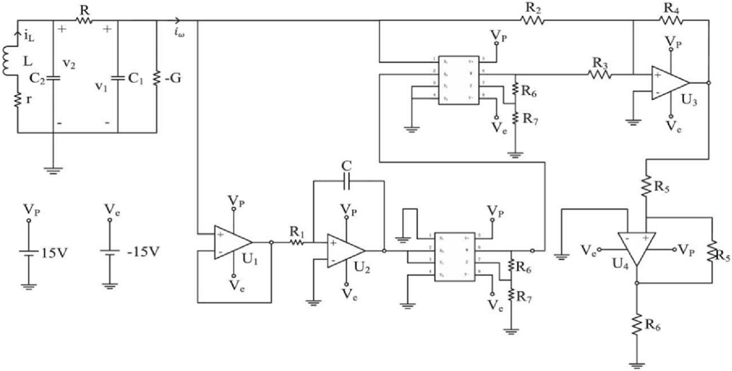
Figure 1. Complete circuit of memristor chaotic circuit [30].
By simplifying the model and introducing variables
In this article, we take the parameters
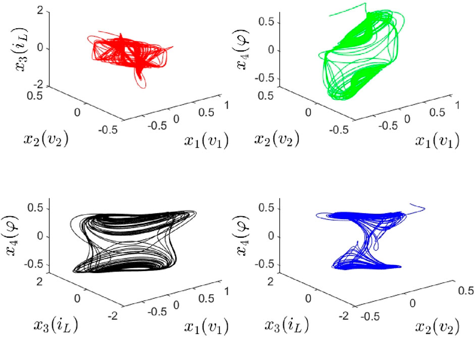
Figure 2. 3D portraits of MCC (Equation 6) or (Equation 5).
3 Main results
3.1 Adaptive fast synchronization without noisy perturbations
Take the aforementioned MCC model (Equation 6) as the drive system, and the related response MCC system containing four controllers,
where
Definition 2. The finite-time synchronization between the drive-response MCC systems (Equations 6, 7) is achieved, if there exists settling-time function
and
In order to realize fast synchronization between MCCs (Equations 6, 7), the control protocol can be designed as follows:
and two gains
in which the index
Remark 1. From the designed control scheme (Equations 9, 10), one can observe that there is no any discontinuous function in it, whereas the traditional finite-time control usually contains the signum and absolute value functions [30]. Thus, the tremor issue has been successfully overcome by this investigation. In addition, the proposed control protocol is adaptive, in which the control gains
Theorem 1. The finite-time synchronization for the MCC systems (Equations 6, 7) will be realized by utilizing adaptive non-chattering control strategy (Equations 9, 10), if
Proof of Theorem 1. Selecting the following Lyapunov function candidate.
differentiating it, and combining with (Equations 8, 10), we obtain
If
According to Lemma 3, we get
In the light of Lemma 1, the finite-time synchronization between the MCC systems (Equations 6, 7) has been achieved, and the settling-time
Remark 2. From (Equation 12), one can find that the upper-bound of
3.2 Adaptive fast synchronization with noisy perturbations
Because the stochastic noise is ubiquitous in man-made and natural systems, this subsection further discusses the problem of finite-time synchronization between MCCs in noisy environments. In contrast to the deterministic model (Equation 6), the dynamics of drive MCC system disturbed by noise is ruled as
and now the response MCC system containing four controllers
where the noise intensity
Definition 3. The stochastic finite-time synchronization for the drive-response MCC systems (Equations 13, 14) is achieved in probability, if there exists settling-time function
and
In particular, for the noise function, we must make the following assumption for achieving fast synchronization analytically.
Assumption 1. The noise function
and
Theorem 2. The stochastic finite-time synchronization for drive-response MCC systems (Equations 13, 14) will be realized by implementing the same adaptive non-chattering control scheme (Equations 9, 10), if
Proof of Theorem 2. Consider the same Lyapunov function candidate.
Let the operator
According to Assumption 1, we obtain
If g ≥ α2 + ql1 ρ12, ql2 ρ22 ≤ 1, ql3 ρ32 ≤ α4, c ≥ l4 ρ42 , then
By Lemma 3, we get
By Lemma 2, the stochastic finite-time synchronization between the drive-response MCC systems (Equations 13, 14) can be achieved, and the settling-time function
Remark 3. From (Equation 16), one can find that the time expectation
Remark 4. In the drive-response MCC systems (Equations 13, 14),
4 Numerical experiments
To verify the theoretical results, numerical simulations are conducted. Various scenarios with different noise intensities are tested, demonstrating the effectiveness of the proposed adaptive control strategy in achieving rapid synchronization of memristor chaotic circuits.
4.1 Adaptive fast synchronization of MCCs
The initial values and parameters contained in the drive MCC system (Equation 5) or (Equation 6) have been given between Equation 6; Figure 2. For the response MCC system (Equation 7), we set the initial condition
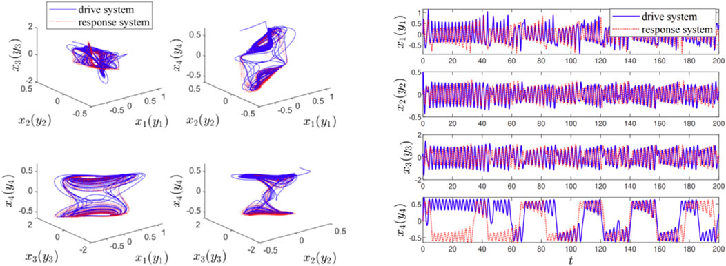
Figure 3. (left) The 3-dimensional attractor phase diagrams and (right) the state trajectories of variables
Now, we implement the designed adaptive finite-time control scheme (Equations 9, 10) for the response MCC system (Equation 7), in which the linear control gains
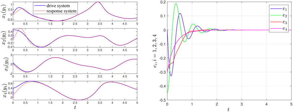
Figure 4. (left) Synchronizing state and (right) synchronization error between drive-response MCC systems (Equations 6, 7) with employing control scheme (Equations 9, 10).
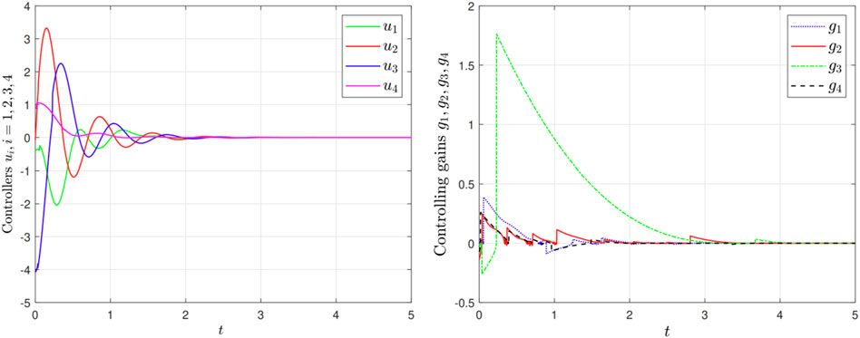
Figure 5. (left) Control signals
Furthermore, we know that the proposed adaptive finite-time control protocol (Equation 9) is non-chattering which has been reflected by the Figure 5 (left), whereas the traditional control scheme is usually designed as follows:
in which the parameters and control gains, including linear and nonlinear term, can be the same as those in (Equations 9, 10) except for the index
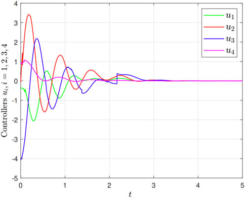
Figure 6. The traditional chattering control scheme (Equation 17).
4.2 Stochastic fast synchronization of MCCs in noisy environments
This subsection further considers the influence of environmental noise on the MCC systems. In the drive-response MCC systems (Equations 13, 14), we take the noisy intensity
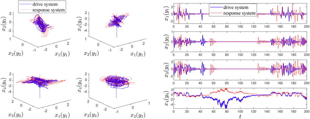
Figure 7. In noisy environments, (left) the 3-dimensional attractor phase diagrams and (right) the state trajectories of variables between drive-response MCC systems (Equations 13, 14) without any control.
In the noisy environments, we also employ the previous proposed adaptive finite-time control protocol (Equations 9, 10) for the response system (Equation 14). In this case, the stochastic drive-response MCC systems (Equations 13, 14) can also be synchronized within time
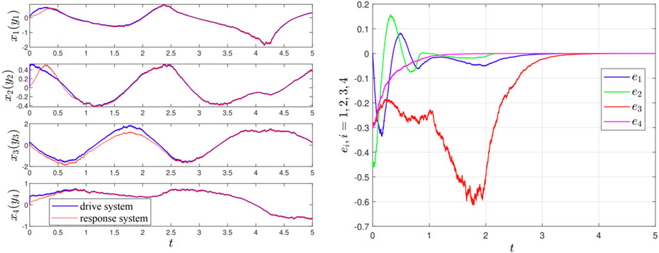
Figure 8. In noisy environments, (left) stochastic synchronizing state and (right) synchronization error between drive-response MCC systems (Equations 13, 14) with employing control scheme (Equations 9, 10).
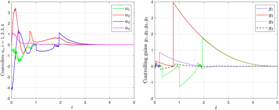
Figure 9. (left) Control signals
Next, we test the effect of different noisy intensities,
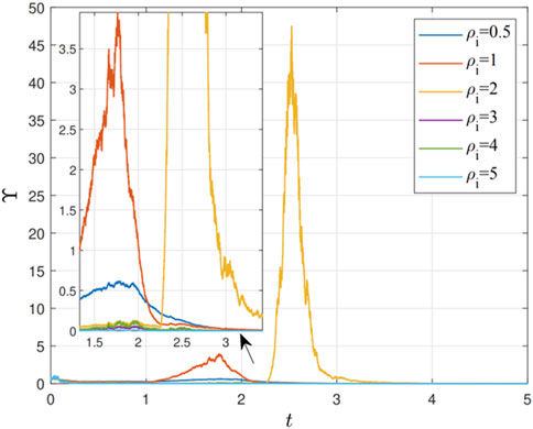
Figure 10. The total error
4.3 Application into image encryption transmission
Algorithm 1.Pseudocode for the Encryption Algorithm.
Step 1. Read the original image and generate the plaintext matrix.
Step 2. Reorganize plaintext matrix into the sequence
Step 3. Utilize the ode45 method to solve state equations of the MCCs with the sampling interval
Step 4. Code discrete chaotic sequences as follows:
Step 5. Convert the binary sequence
Step 6. Encryption function executes an XOR operation:
In which
Step 7. Convert the DNA ciphertext sequence
Finally and importantly, we apply the proposed adaptive fast control strategy (Equations 9, 10) into image encryption transmission. Let’s begin by introducing the DNA algorithm briefly. It is widely recognized that DNA sequences consist of four types of deoxyribonucleotides: adenine (A), guanine (G), cytosine (C), and thymine (T). In a similar manner, binary coding also has a complementary nature between the digits 0 and 1. As per the base pairing principle, binary data can be represented in eight different DNA encodings, as illustrated in Table 1. By converting binary data into a DNA sequence, we can select any one of these eight encoding methods. Building on this straightforward DNA sequence algorithm, we propose an image encryption method, with the encryption and decryption processes depicted in Figure 11. The drive system (Equation 13) and response system (Equation 14) are employed to produce chaotic sequences in the encrypter and decrypter, respectively, incorporating the DNA method as given in Algorithm 1. Using the proposed adaptive fast method for the image `Baboon', the simulation outcomes are depicted in Figure 12, where subfigure (a) represents the original image to be encrypted, subfigure (b) shows the scrambled encrypted image which appears disordered, and subfigure (c) displays the recovered image almost identical to (a). Therefore, the practicality of Theorem 1 or Theorem 2 and the effectiveness of finite-time fast synchronization between drive-response MCCs have been confirmed.
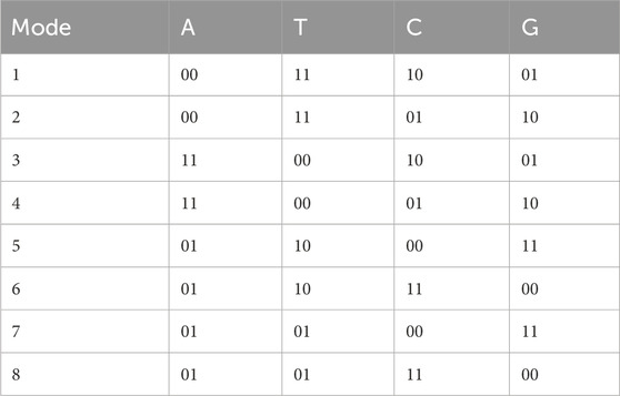
Table 1. Method of DNA encoding.
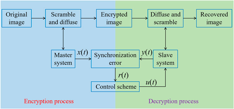
Figure 11. The image transmission process.

Figure 12. (A) Original image. (B) Encrypted image. (C) Recovered image.
Correlation analysis. We test the correlation of 10,000 pairs of neighboring pixels in the horizontal, vertical, and diagonal directions, respectively. The calculation of correlation coefficient (CC) can be expressed as
in which
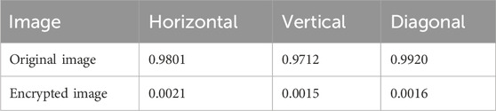
Table 2. Correlation coefficients of adjacent pixels in Baboon’s image.
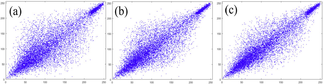
Figure 13. Correlation distributions in (A) horizontal, (B) vertical, and (C) diagonal directions of original image.
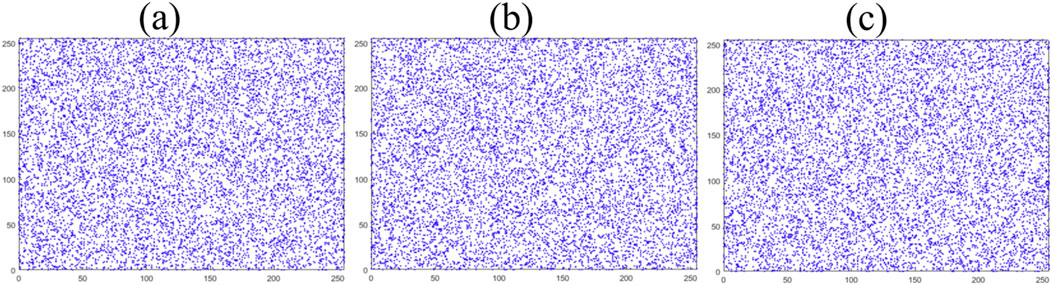
Figure 14. Correlation distributions in (A) horizontal, (B) vertical, and (C) diagonal directions of encrypted image.
Entropy analysis. The information entropy is often used to measure the bit distribution per level of the image’s pixel values, which is defined as
in which
Histogram analysis. In this subsection, the histograms of the original image are compared to those of the encrypted image. Each image possesses unique histograms that reveal the effects of the image encryption algorithm’s scrambling. Histograms can directly show the statistical differences in the image before and after encryption. To thwart attackers from deciphering the image data through gray value distribution analysis, the histogram of the encrypted image should be smooth and uniform. Figure 15 displays the histograms of Figure 12A in the red, green, and blue channels, showing steep and fluctuating shapes. Conversely, Figure 16 presents the histograms of the encrypted image across the red, green, and blue channels, demonstrating uniform distributions. This uniformity indicates that statistical attacks will not allow an attacker to extract accurate information from Figure 12A using Figure 12B.
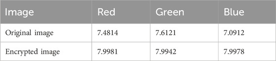
Table 3. Information entropy of Baboon’s image.
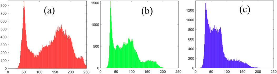
Figure 15. (A) Red, (B) green, and (C) blue histograms of original image.
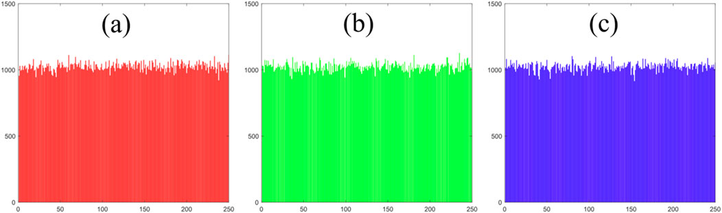
Figure 16. (A) Red, (B) green, and (C) blue histograms of encrypted image.
5 Conclusion
This study presents an innovative adaptive control strategy for fast synchronization of memristor chaotic circuits, both with and without noisy perturbations. The developed control strategy is adaptive, addressing the issue of uncertain selection of the associated controlling gains as they can adapt according to the predesigned adaptive laws. Specifically, the associated controlling gains eventually reduce to zero upon achieving synchronization, thereby minimizing the control cost. Furthermore, using the second Lyapunov method, sufficient criteria have been progressively established to achieve finite-time and stochastic finite-time synchronization of MCCs. Numerical experiments validate the theoretical conclusions and emphasize potential applications in areas like image encryption transmission. Given that the time estimation for finite-time convergence is linked to the initial conditions of MCCs, future research can utilize the proposed adaptive non-chattering control to investigate fixed-time or predefined-time synchronization.
Data availability statement
The original contributions presented in the study are included in the article/supplementary material, further inquiries can be directed to the corresponding author.
Author contributions
BY: Writing–original draft, Validation, Project administration, Methodology, Funding acquisition, Conceptualization. HX: Writing–original draft, Conceptualization. LH: Writing–original draft, Software, Methodology. JW: Writing–review & editing, Software, Funding acquisition.
Funding
The author(s) declare that financial support was received for the research, authorship, and/or publication of this article. This research was funded by the Science and Technology Foundation of Qingyang, China (QY-STK-2022A-017) and the National Natural Science Foundation of China (grant No. 62103166).
Acknowledgments
The authors are grateful to the Longdong University, Henan Technical College of Construction, China University of Mining and Technology, and Jiangnan University.
Conflict of interest
The authors declare that the research was conducted in the absence of any commercial or financial relationships that could be construed as a potential conflict of interest.
Publisher’s note
All claims expressed in this article are solely those of the authors and do not necessarily represent those of their affiliated organizations, or those of the publisher, the editors and the reviewers. Any product that may be evaluated in this article, or claim that may be made by its manufacturer, is not guaranteed or endorsed by the publisher.
References
1. Chua L. Memristor-the missing circuit element. IEEE Trans Circuit Theor (1971) 18(5):507–19. doi:10.1109/TCT.1971.1083337
2. Strukov DB, Snider GS, Stewart DR, Williams RS. The missing memristor found. Nature (2008) 453(7191):80–3. doi:10.1038/nature06932
3. Sun J, Shen Y, Yin Q, Xu C. Compound synchronization of four memristor chaotic oscillator systems and secure communication. Chaos (2013) 23(1):013140. doi:10.1063/1.4794794
4. Lin Z, Wang H. Efficient image encryption using a chaos-based PWL memristor. IETE Tech Rev (2010) 27(4):318–25. doi:10.4103/0256-4602.64605
5. Yao X, Chen X, Liu H, Sun L, He L. Adaptive sliding-mode synchronization of the memristor based sixth-order uncertain chaotic system and its application in image encryption. Front Phys (2022) 14(10):863668. doi:10.3389/fphy.2022.863668
6. Berdan R, Lim C, Khiat A, Papavassiliou C, Prodromakis T. A memristor SPICE model accounting for volatile characteristics of practical ReRAM. IEEE Elec Dev Lett (2013) 35(1):135–7. doi:10.1109/LED.2013.2291158
7. Pershin YV, Di Ventra M. Experimental demonstration of associative memory with memristive neural networks. Neural Netw (2010) 23(7):881–6. doi:10.1016/j.neunet.2010.05.001
8. Liu X, Wang J. The simplest memristor circuit with hyperchaos. Front Phys (2022) 15(10):904200. doi:10.3389/fphy.2022.904200
9. Muthuswamy B. Implementing memristor based chaotic circuits. Int J Bifur Chaos (2010) 20(05):1335–50. doi:10.1142/S0218127410026514
10. Bao B, Ma Z, Xu J, Liu Z, Xu Q. A simple memristor chaotic circuit with complex dynamics. Int J Bifur Chaos (2011) 21(09):2629–45. doi:10.1142/S0218127411029999
11. Li Q, Hu S, Tang S, Zeng G. Hyperchaos and horseshoe in a 4D memristive system with aline of equilibria and its implementation. Int J Circuit Theor Appl. (2014) 42(11):1172–88. doi:10.1002/cta.1912
12. Li Q, Zeng H, Li J. Hyperchaos in a 4D memristive circuit with infinitely many stable equilibria. Nonlinear Dynam (2015) 79:2295–308. doi:10.1007/s11071-014-1812-4
13. Kountchou M, Louodop P, Bowong S, Fotsin H, Kurths J. Optimal synchronization of a memristive chaotic circuit. Int J Bifur Chaos (2016) 26(06):1650093. doi:10.1142/S0218127416500930
14. Tian A, Fu C, Su XY, Yau HT, Xiong H. Classifying and predicting salinization level in arid area soil using a combination of Chua’s circuit and fractional order sprott chaotic system. Sensors (2019) 19(20):4517. doi:10.3390/s19204517
15. Yan S, Wang E, Wang Q, Sun X, Ren Y. Analysis, circuit implementation and synchronization control of a hyperchaotic system. Phys Scr (2021) 96(12):125257. doi:10.1088/1402-4896/ac379b
16. Khan N, Muthukumar P. Transient chaos, synchronization and digital image enhancement technique based on a novel 5D fractional-order hyperchaotic memristive system. Circuits Syst Signal Proc (2022) 41(4):2266–89. doi:10.1007/s00034-021-01892-6
17. Liu J, Wang Z, Chen M, Zhang P, Yang R, Yang B. Chaotic system dynamics analysis and synchronization circuit realization of fractional-order memristor. Euro Phys J Spec Top (2022) 231(16):3095–107. doi:10.1140/epjs/s11734-022-00640-4
18. Cao S, Zhao T, Wang G, Zhang T, Liu C, Liu Q, et al. A mechanical defect localization and identification method for high-voltage circuit breakers based on the segmentation of vibration signals and extraction of chaotic features. Sensors (2023) 23(16):7201. doi:10.3390/s23167201
19. Yang S, Li C, Huang T. Synchronization of coupled memristive chaotic circuits via state dependent impulsive control. Nonlinear Dynam (2017) 88(1):115–29. doi:10.1007/s11071-016-3233-z
20. Zou L, Peng Y, Feng Y, Tu Z. Stabilization and synchronization of memristive chaotic circuits by impulsive control. Complexity (2017) 317:1–10. doi:10.1155/2017/5186714
21. Wang S, Wang X, Zhou Y. A memristor-based complex Lorenz system and its modified projective synchronization. Entropy (2017) 17(11):7628–44. doi:10.3390/e17117628
22. Wang S. A novel memristive chaotic system and its adaptive sliding mode synchronization. Chaos Solitons Fractals (2023) 172:113533. doi:10.1016/j.chaos.2023.113533
23. Wu H, Li R, Wei H, Zhang X, Yao R. Synchronization of a class of memristive neural networks with time delays via sampled-data control. Int J Mach Learn Cyber (2015) 6:365–73. doi:10.1007/s13042-014-0271-z
24. Rakkiyappan R, Sivasamy R, Li X. Synchronization of identical and nonidentical memristor-based chaotic systems via active backstepping control technique. Circuits Syst Signal Proc (2015) 34:763–78. doi:10.1007/s00034-014-9883-5
25. Xiao W, Min F, Li H, Shi W. Complex motion behavior and synchronization analysis of heterogeneous neural network. IEEE Trans Circuits Syst Reg Pap (2024) 1–10. early access. doi:10.1109/TCSI.2024.3387560
26. Li H, Min F. Large-scale memrisitive rulkov ring-star neural network with complex spatio-temporal dynamics. IEEE Trans Ind Inf (2024) 20:10259–68. early access. doi:10.1109/TII.2024.3393563
27. Cang S, Chen Z, Wang Z, Jia H. Projective synchronisation of fractional–order memristive systems with different structures based on active control method. Int J Sensor Netw (2013) 14(2):102–8. doi:10.1504/IJSNET.2013.056609
28. Akgul A, Rajagopal K, Durdu A, Pala MA, Boyraz OF, Yildiz MZ. A simple fractional-order chaotic system based on memristor and memcapacitor and its synchronization application. Chaos Solitons Fractals (2021) 152:111306. doi:10.1016/j.chaos.2021.111306
29. Jiang H, Zhuang L, Chen C, Wang Z. Hidden dynamics and hybrid synchronization of fractional-order memristive systems. Axioms (2022) 11(11):645. doi:10.3390/axioms11110645
30. Wang L, Dong T, Ge MF. Finite-time synchronization of memristor chaotic systems and its application in image encryption. Appl Math Comput (2019) 347:293–305. doi:10.1016/j.amc.2018.11.017
31. Ahmad I, Shafiq M, Naderi B. Finite-time synchronization of four-dimensional memristor-based chaotic oscillator and applied to secure communication systems. Franklin Open (2023) 3:100015. doi:10.1016/j.fraope.2023.100015
32. Wang J, Tian Y, Hua L, Shi K, Zhong S, Wen S. New results on finite-time synchronization control of chaotic memristor-based inertial neural networks with time-varying delays. Mathematics (2023) 11(3):684. doi:10.3390/math11030684
33. Wang L, Jiang S, Ge MF, Hu C, Hu J. Finite-/fixed-time synchronization of memristor chaotic systems and image encryption application. IEEE Trans Circuits Syst Reg Pap (2021) 68(12):4957–69. doi:10.1109/TCSI.2021.3121555
34. Mirzaei MJ, Aslmostafa E, Asadollahi M, Padar N. Fast fixed-time sliding mode control for synchronization of chaotic systems with unmodeled dynamics and disturbance; applied to memristor-based oscillator. J Vibr Control (2023) 29(9-10):2129–43. doi:10.1177/10775463221075116
35. Wang Y, Li H, Guan Y, Chen M. Predefined-time chaos synchronization of memristor chaotic systems by using simplified control inputs. Solitons Fractals (2022) 161:112282. doi:10.1016/j.chaos.2022.112282
36. Ma R, Huang Z, Xu H. Fixed-time chaotic stabilization and synchronization of memristor chaotic circuits in noisy environments. J Korean Phys Soc (2024) 84(2):90–101. doi:10.1007/s40042-023-00942-3
37. Sambas A, Vaidyanathan S, Tlelo-Cuautle E, Abd-El-Atty B, Abd El-Latif AA, Guillen-Fernandez O, et al. A 3-D multi-stable system with a peanut-shaped equilibrium curve: circuit design, FPGA realization, and an application to image encryption. IEEE Access (2020) 24(8):137116–32. doi:10.1109/ACCESS.2020.3011724
38. Sambas A, Vaidyanathan S, Zhang X, Koyuncu I, Bonny T, Tuna M, et al. A novel 3D chaotic system with line equilibrium: multistability, integral sliding mode control, electronic circuit, FPGA implementation and its image encryption. IEEE Access (2022) 8(10):68057–74. doi:10.1109/ACCESS.2022.3181424
39. Sambas A, Miroslav M, Vaidyanathan S, Ovilla-Martínez B, Tlelo-Cuautle E, Abd El-Latif AA, et al. A New Hyperjerk system with a half line equilibrium: multistability, Period doubling reversals, antimonotonocity, electronic circuit, FPGA design and an application to image encryption. IEEE Access (2024) 12:9177–94. doi:10.1109/ACCESS.2024.3351693
41. Bhat SP, Bernstein DS. Finite-time stability of continuous autonomous systems. SIAM J Control Optim (2000) 38(3):751–66. doi:10.1137/S0363012997321358
42. Yin J, Khoo S, Man Z, Yu X. Finite-time stability and instability of stochastic nonlinear systems. Automatica (2011) 47(12):2671–7. doi:10.1016/j.automatica.2011.08.050
Keywords: chaotic system, nonlinear system, image encryption, adaptive control, synchronization
Citation: Yuan B, Xu H, Hu L and Wu J (2024) Adaptive strategy for achieving fast synchronization between two memristor chaotic circuits without and with noisy perturbation. Front. Phys. 12:1445805. doi: 10.3389/fphy.2024.1445805
Received: 08 June 2024; Accepted: 22 August 2024;
Published: 09 September 2024.
Edited by:
Juan Manuel López, Institute of Physics of Cantabria, SpainReviewed by:
Aceng Sambas, Sultan Zainal Abidin University, MalaysiaFuhong Min, Nanjing Normal University, China
Copyright © 2024 Yuan, Xu, Hu and Wu. This is an open-access article distributed under the terms of the Creative Commons Attribution License (CC BY). The use, distribution or reproduction in other forums is permitted, provided the original author(s) and the copyright owner(s) are credited and that the original publication in this journal is cited, in accordance with accepted academic practice. No use, distribution or reproduction is permitted which does not comply with these terms.
*Correspondence: Binhua Yuan, MTMxNTAxMzg2NDhAMTYzLmNvbQ==