 Wolfgang Lechner
 Barbara Knäusl
 Jacob Brunner
 Dietmar Georg
 Peter Kuess
- 1Division of Medical Physics, Department of Radiation Oncology, Medical University of Vienna, Vienna, Austria
- 2Christian Doppler Laboratory for Image and Knowledge Driven Precision Radiation Oncology, Department of Radiation Oncology, Medical University of Vienna, Vienna, Austria
- 3Medical Physics, MedAustron Ion Therapy Center, Wiener Neustadt, Austria
This work aimed to characterize a dedicated phantom for assessing the dose near metal implants for radiotherapy with photons and protons. A dosimetry audit phantom was redesigned to position a Gafchromic EBT-3 film within a bisected titanium pedicle screw (6.5 mm diameter). The mass density and the water equivalent thickness (WET) of the phantom material were determined. The phantom was irradiated using a photon arc and a horizontal proton beam in combination with a couch rotation of 20°, with three repeated measurements each. Treatment plans utilizing a single field covering the screw and the EBT-3 film were optimized to deliver a physical dose of 2 Gy using a collapsed cone and Monte Carlo dose engine for photons and protons, respectively. The mass density and the WET of the phantom were determined as (1.033
1 Introduction
The clinical practice in radiation oncology has changed considerably during the last decade. First, precision radiotherapy techniques based on fluence modulation and image guidance became the new standard. Second, the aging population, characterized by comorbidities and/or prior radiotherapy, along with those having oligometastatic disease represent a new and continuously growing patient cohort. In light of this overall new setting in radiation oncology, some challenges remained. One of those are metallic implants, such as hip prostheses, dental fillings or metallic screws, which lead to imaging artifacts and consequently affect target volume and organ at risk delineation [1]. Next, these imaging artifacts can impair dose calculation accuracy and metal implants can be associated with other dosimetric effects, like local dose hot spots at their tissue interfaces.
Giantsoudi et al. provided a topical review on metal artifacts in Computed Tomography (CT) imaging and briefly outlined the dosimetric effects [2]. They concluded that dosimetric errors of more than 25% can arise in dose calculation near hip prostheses. These discrepancies are reduced to a level of approximately 12% near dental implants. However, their findings are mainly based on dose calculation considering the presence of imaging artifacts than discrepancies found in actual measurements. However, imaging artifacts and inaccuracies in structure segmentation can be overcome by state-of-the art metal artifact reduction algorithms, which have been further improved by applying deep learning algorithms [3].
Dosimetric effects caused by metallic implants remain a challenge, which have been explored in the context of dose calculation algorithm assessment, mainly for photon beam therapy [4–8]. For example, Pawałowski et al. compared an advanced pencil beam algorithm, a Boltzmann equation solver based algorithm with Monte Carlo (MC) simulations and found an agreement within 4% for titanium and tungsten for a static field without fluence modulation [7]. Gnanasambandam et al. reported an overall cumulative uncertainty of the delivered dose of more than 3% for metal inserts in photon beam therapy. They have investigated low- and high-density metal inserts (aluminum, titanium, stainless steel, cerrobend, amalgam, and gold) for 6, 10 and 15 MV photon beams as well as 6 and 10 MV beams in flattening filter free mode. Unfortunately, their work lacked experimental validation, similar to many published studies investing metal implants in photon beam therapy [9].
Effects of metallic implants in proton therapy are a matter of research as well. Jia et al. investigated the effect of dose perturbations for two metallic spinal screw implants in proton beam therapy using radiochromic film dosimetry [10]. They concluded that the dose enhancement effect at interfaces was not correctly modeled by their pencil beam algorithm. Verburg and Seco performed a detailed study on implants for proton therapy and pointed at the change of Coulomb scattering for various proton energies and titanium thicknesses [11]. They investigated also the potential impact on chordoma patient treatments for a passive scattering beam delivery technique. However, this beam delivery technique has been eclipsed by pencil beam scanning as the preferred dose delivery technique in particle beam therapy. Another effect caused by metal implants in particle therapy is related to changes in the linear energy transfer (LET), as reported by Oancea et al. [12]. Their analyses showed that the number of particles, detected in the interval from 92 to 100
The development of dedicated phantoms plays a vital role in current radiotherapy practice. The applications range from simple phantoms for checking basic beam parameters to phantoms capable of performing 4D-dosimetry within moving targets [13, 14]. With the increasing demand for flexibility the use of in-house produced components, e.g., employing additive manufacturing methods, became crucial [15–17]. Moreover, phantoms also serve as backbone for modern dosimetry audit services which help to improve the quality of dose delivery around the world [18–25].
The present study aims to report on a dedicated phantom for investigating dosimetric effects for small metallic implants in advanced radiotherapy. As a use case a typical metal screw as used in spinal surgery was selected and feasibility studies were performed in both photon and proton therapy. This type of screw is often placed in close proximity of the spinal cord where dosimetric errors can have a severe effect.
2 Materials and methods
2.1 Phantom design
The design of the phantom was based on a dedicated phantom for remote audits developed and manufactured within the framework of a coordinated research project hosted by the International Atomic Energy Agency (IAEA). This phantom consisted of several slabs made of polystyrene. Fully assembled, the phantom had outer dimensions of 15 cm
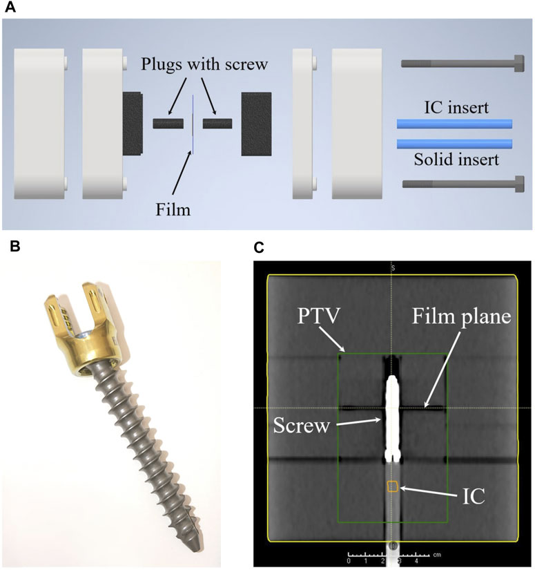
Figure 1. (A) Shows an explosion sketch of the whole phantom. (B) A picture of the VERTAUX pedicle screw which was used in this work. (C) An isocentric coronal slice of a CT scan of the assembled phantom including the screw. The green box illustrates the target region (PTV) later used for irradiation, while IC indicates the position of the ionization chamber.
2.2 Irradiation and imaging
An Elekta Versa HD linear accelerator (Elekta AB, Stockholm, Sweden) was used for the photon experiments. Proton irradiations were conducted at the horizontal research beam line of the synchrotron-based Ion Therapy Center MedAustron (Wiener Neustadt, Austria) [26, 27].
Photon dose calculation employed CT scans were acquired with a Siemens Somatom Definition AS CT scanner (Siemens Healthineers AG, Erlangen, Germany) using clinical scan settings (exposure modulation 70–250 mAs, 120 kVp, 2 mm slice thickness and 50 cm reconstruction diameter) with the iterative metal artifact reduction algorithm.
CT scans for proton dose calculation were performed at a Big Bore CT scanner (Philips, Netherlands) using the clinical scan settings (300 mAs, 120 kVp, 2 mm slice thickness and 35 cm reconstruction diameter) without metal artifact reduction algorithm. The phantom was positioned using laser markers during all imaging and irradiation steps. Indexing bars assured the reproducible alignment during the entire workflow.
2.3 Mass density and water equivalent thickness determination
The mass density of the phantom was assessed by the ratio of the mass to the volume of a slab with a simple geometry. The dimensions of the slab were determined using a caliper and the mass was determined using four different scales.
We determined the Water Equivalent Thickness (WET) of the material using a 148.2 MeV proton beam (FHWM = 9.7 mm,
2.4 Treatment plan generation
Independent of the treatment modality (photon or proton), three different sets of treatment plans were generated: 1) One treatment plan was generated where the same specific mass density was assigned to the whole phantom (PS) simulating the situation where no screw is present. The material override was based on the chemical composition of polystyrene with a specific mass-density of 1.033
The aim during treatment plan optimization was to generate treatment plans with a homogeneous dose distribution in the target using a similar set-up for both photons and protons. The target volume of 422 cm3 was designed to cover the film and the ionisation chamber as depicted in Figure 1C. Homogeneity of the target was defined as the near-minimum dose
The photon treatment plans (i.e., X-HU, X-PS and X-Ti) were calculated using the Treatment Planning System (TPS) RayStation (V12A SP1, RaySearch, Stockholm, Sweden) employing the collapsed cone (CC) dose engine v5.7. The isotropic dose calculation grid was 2 mm and 1 mm for optimization and final dose calculation, respectively. These plans were created using a 6 MV beam with flattening filter and Volumetric Modulated Arc Therapy (VMAT) as treatment technique. The arc length of the VMAT beam was 200° (start angle 260°, stop angle 100°) to avoid irradiation through the couch. A couch rotation of 340° was used to irradiate the film at an oblique angle. Additionally, the X-PS and the X-HU plans were recalculated using the SciMoCa MC algorithm (V1.7.2.5381, Scientific RT GmbH, Munich, Germany) with a 1 mm grid size, the lowest MC uncertainty setting available and dose-to-water conversion. X-Ti was not recalculated as SciMoCa does not allow to assign titanium to a structure but rather detects the material titanium based on the CT number.
All three proton treatment plans (p-HU, p-PS and p-Ti) were generated using the TPS RayStation (V2023B, RaySearch, Stockholm, Sweden) employing the MC dose engine v5.5. To ensure a homogenous spot distribution, a grid of 3 mm was used for plan optimisation and final dose calculation (statistical MC uncertainty 0.5%,
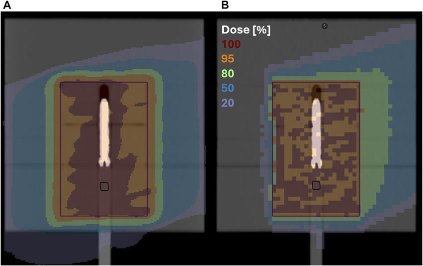
Figure 2. A cranial slice through the dose distribution at the isocenter calculated based on the original CT densities with a 20° couch rotation; (A) photon VMAT plan with a 1 mm calculation grid; (B) proton plan with 1 beam and a 3 mm calculation grid; the black structure represents the position of the semiflex chamber and the purple square the target volume.
2.5 Dosimetry and
EBT-3 films (Ashland, Wayne, NJ, United States) were used during photon (lot #11192002) and proton (lot #03082203) irradiations. In addition to the films a PTW 31010 Semiflex IC (PTW Dosimetry, Freiburg, Germany) was placed inside the phantom and used in combination with Unidos webline electromter (PTW Dosimetry, Freiburg, Germany). Each measurement was repeated three times determining the standard deviation. The results of the measurements were corrected for daily output variations of the therapy unit for the photon plans but not for the proton plans. The latter was reflected in the uncertainty budget.
Films underwent scanning before irradiation and again at 24 h post-irradiation with three repetitions. The scanning was performed using an Epson 11000 XL for protons, and an Epson Expression 12000 XL flatbed scanner for photons (EPSON, Suwa, Nagano, Japan). All scans were acquired in 48-bit RGB color channel (16 bits per color) transmission mode, with a resolution of 150 dpi (0.169 mm/pixel), with all available color correction options turned off and saved in the tagged image file format (tiff). Optical density was calculated as described by Khachonkham et al. [29]. The proton calibration curve was measured in the plateau region of a 148 MeV 10 cm
A
2.6 Analysis
The calculated and measured dose distributions were analyzed using the Verisoft software (PTW Dosimetry, Freiburg, Germany). The measured and calculated dose distributions were aligned using the position of the pins on the film. The dose distributions of each film and and the corresponding calculated dose distributions were re-normalized to a dose value of 2 Gy at the same point in a homogeneous dose region at least 2 cm away from the screw in direction of the entrance region of the proton beam. Two different line profiles were extracted from each film. For both beam modalities a horizontal profile through the center of the screw was employed. For the photon plans, a vertical profile was extracted through the screw’s center, whereas for the proton plans, the profile was located 10 mm behind the screw (see Figure 3).
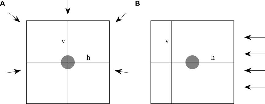
Figure 3. An illustration of how the films were irradiated and where the horizontal (h) and vertical (v) line profiles were located. (A) Shows the photon and (B) the proton irradiation. The grey area indicates the position of the screw. The arrows indicate the incident angels of the irradiation.
The line profiles in horizontal direction were calculated as follows: First, the mean value
With
The confidence interval (CI) was calculated by multiplying
3 Results
3.1 Mass density and water equivalent thickness determination
The mass-density was determined as (1.033
3.2 Absorbed dose to water determination
The results of the absorbed dose to water determination using the ionization chamber for the photon and proton experiments are summarized in Table 1. The magnitude of the temperature and pressure correction was (1.019
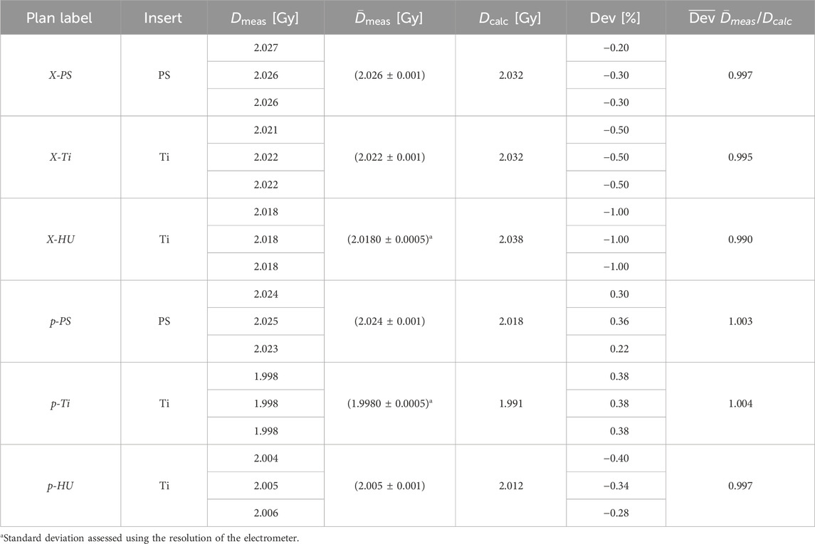
Table 1. The three photon (X) and the three proton (p) plan scenarios were irradiated with either the titanium screw as insert (Ti) or a polystyrene pin (PS).
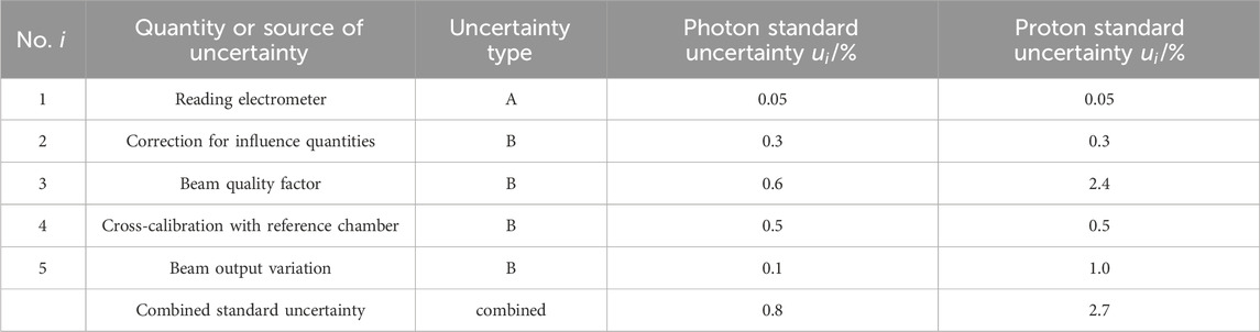
Table 2. The uncertainty budget for absorbed dose to water determination. All standard uncertainties are with a coverage factor of
3.3 Relative dosimetry
On average, the CI was 2.2% and 1.7% for the photon and proton plans, respectively. This difference between the CIs of the photon and proton irradiation was tested using Fisher’s F-test, which showed a p-value of 0.278 which indicated no statistically significant difference between the two modalities. The measured dose of the X-PS plans showed excellent agreement with the dose calculated using the RayStation photon CC and the SciMoCa MC algorithm as shown in Figures 4A, B. The measured and calculated horizontal profile of the X-HU plan and the X-Ti agreed within the CI in regions located at a distance larger than 5 mm from the center of the screw for both algorithms. Significant deviations exceeding 10% were found between the calculated and measured values at the interface between phantom material and the screw as well as within the screw, for the RayStation CC photon dose calculation (see Figures 4C–F). In contrast to that, the SciMoCa MC algorithm agreed within the CI with the measured dose within a region of 10 mm around the screw as depicted in Figures 4C, D. The vertical profile of the X-HU plan displayed in Figure 4D showed an overestimation of approximately 3% of the calculated dose with both algorithms between the coordinates
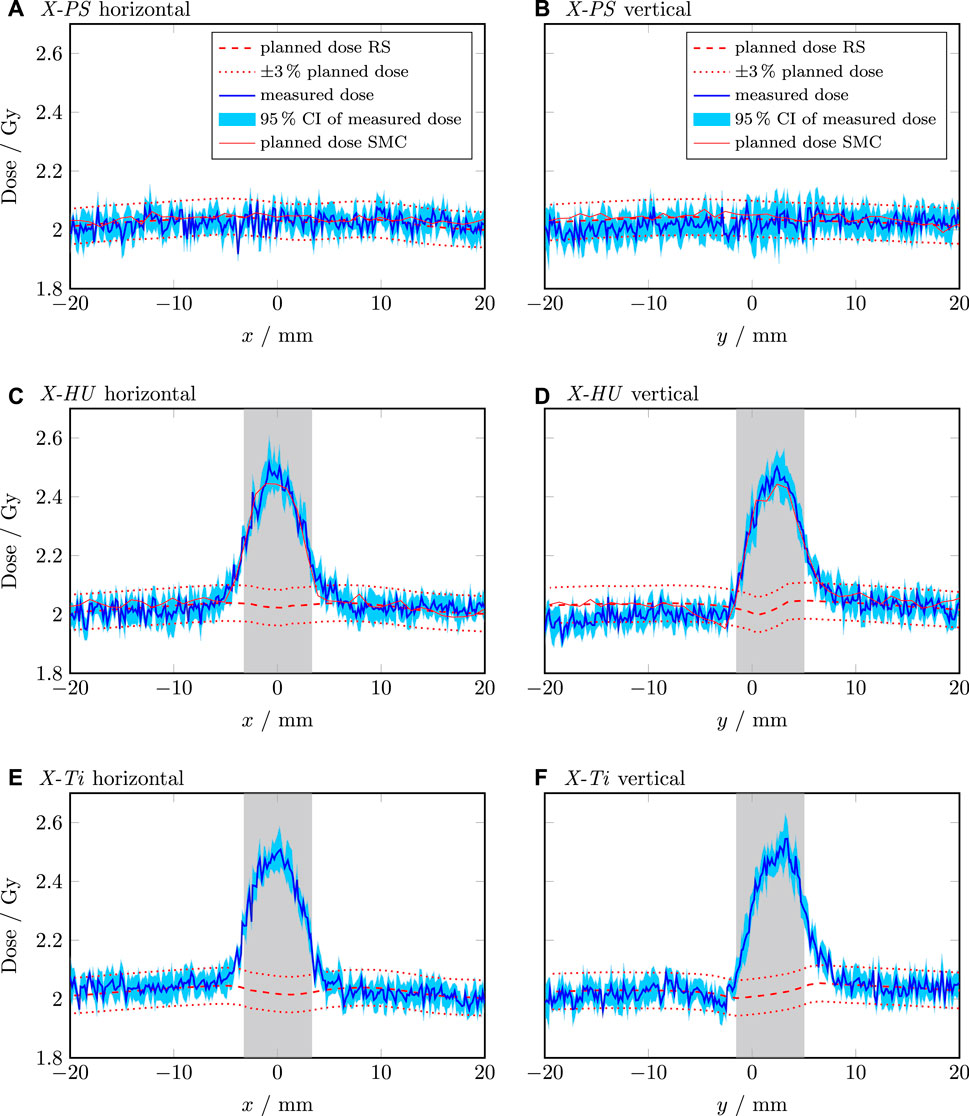
Figure 4. Line dose profiles of the photon plans. The horizontal and vertical profile of the X-PS plan are shown in (A,B), respectively. The horizontal and vertical profile of the X-HU plan are shown in (C,D), respectively. The horizontal and vertical profile of the X-Ti plan are shown in (E,F), respectively. The shaded grey area indicates the position and extension of the screw. The dashed red line is the dose calculated by RayStation (RS). The dotted red lines indicate
The p-PS showed a gradual decrease in dose of approximately 3% across the horizontal and the vertical profile despite the homogeneous material composition as illustrated in Figures 5A, B. Compared to the dose calculated for the p-HU plan, the measured dose decreased by more than 5% in the exit region of the beam (behind the screw). In contrast to the photon plans, no dose increase in the screw itself occurred. However, significant dose fluctuations of more than 5% were observed in the exit region of the beam as shown in Figures 5C–F. Using the material overriding technique in p-Ti improved by approx. 2% the dose calculation accuracy on average compared to p-HU in the exit region of the beam, but dose fluctuations were also observed in this scenario.
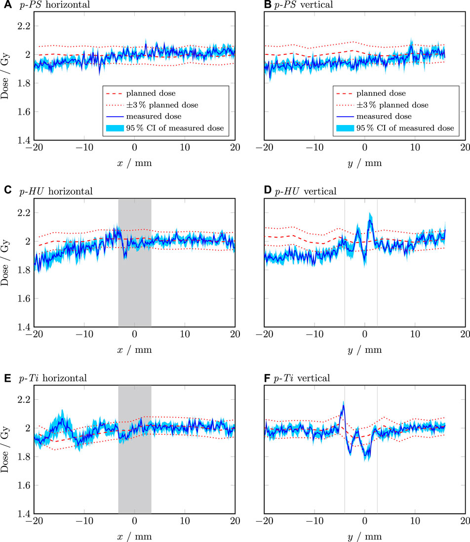
Figure 5. Line dose profiles of the proton plans. The horizontal and vertical profile of the p-PS plan are shown in (A,B), respectively. The horizontal and vertical profile of the p-HU plan are shown in (C,D), respectively. The horizontal and vertical profile of the p-Ti plan are shown in (E,F), respectively. The shaded grey area indicates the position and extension of the screw. The dashed red line is the dose calculated by RayStation (RS). The dotted red lines indicate
Recalculating the p-HU plan (3 mm grid size) with smaller resolution revealed more than 60% dose difference behind the screw for a 1 mm grid. More distant points, e.g., the position of the semiflex chamber, were not affected.
3.4
Measurement of the titanium screw 96 h after the proton irradiation detected the following isotopes; 44Sc, 46Sc, 47Sc, and 48V with an activity per gram of 0.77
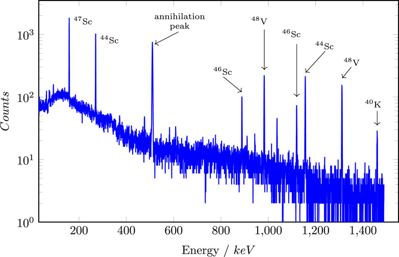
Figure 6. Gamma-energy spectrum of the titanium screw in logarithmic scale.
4 Discussion
This work focused on the characterization of a phantom for the acquisition of 2D dose profiles near small metal implants. The mass density of the phantom material agreed within one standard uncertainty with the generic value specified in the original publication [23]. Using the value determined in our work led to an agreement of absorbed dose between calculation and measurement of less than 0.3%. The difference between the PS and the HU plans was 0.7% and 0.6% for the photon and proton plans, respectively. This shows the impact of mass density variations on dose calculation. However, the mass density showed a larger discrepancy (more than two standard uncertainties) to generic values published in codes of practice such as the IAEA-TRS 398 and IAEA-TRS 483 [30, 31]. This justifies a determination of the mass density of individual phantoms as mass density variations can occur between different manufacturers or different batches. Using the density of 1.06
Besides the determination of absorbed dose delivered by different treatment plans, the presence of the IC also has the advantage, that the repeatability of the set-up and dose delivery can be characterised. In this work, standard deviations of 0.001 Gy at the most were observed, indicating excellent repeatability.
The detection limit of effects related to the presence of metal implants can be defined as the CI of the relative film measurements. The results showed an 0.5% larger CI for the photon measurements compared to the proton measurements. One possible explanation might be a higher homogeneity of the film batch used for protons. This statistically insignificant difference might indicate that both detection limits are statistically equal or that the number of repetitions was too low to show a statistically significant result. The measured dose profiles showed a random variation between neighboring points. This due to variations of thickness of the dye of the film and due to noise of the scanning which was not completely compensated using the averaging of several lines and films. In reality, the dose profile would be smoother. Additional smoothing of the measured profiles was not performed to avoid a deterioration of the spatial resolution. A scanner uniformity correction of the measured dose profiles was not performed as Palmer et al. showed a variation of the scanner uniformity of less than 1% in the scan region used in this work [32].
Film measurements for the proton irradiations showed a decrease in dose at the distal part of the target area. This is in accordance with reports on quenching effects of EBT-3 films caused by the increased LET in this area (e.g., [29, 33, 34]). Moreover, due to the angular distribution of nuclear interactions of a proton beam hitting titanium, dose variations orthogonal to the beam direction occur, as also reported by Oancea et al. [12]. This potentially accounts for the observed dose fluctuations along the vertical profile in Figure 5D. Furthermore, these nuclear scattering effects seem to be accurately modelled in scenario p-Ti by the MC simulations in the TPS. An additional reason for the dose fluctuations behind the screw is the insufficient geometrical modelling of the screw itself. With a slice thickness of 2 mm, a structure resolution of 1 mm and the blurred representation of the screw, the thread cannot be contoured or modelled adequately. Consequently, also the dose calculation is affected by these contouring imperfections.
MC dose calculation became standard for proton therapy. At present speed optimised MC dose engines implemented in clinical TPSs are capable of accurately predicting the dose distribution also in the presence of tissue interfaces [17, 35, 36]. While 2 mm or 3 mm are standard grid dimensions in agreement with the CT resolution, there is no common agreement on an optimal dose calculation grid size in the presence of implants [37, 38]. A thorough analysis of the CT numbers in the screw and its translation to density and SPR reveals an overestimation of the titanium density by up to 100% for grid sizes of 1 and 2 mm as visualised in Figure 7. These results support overriding the screw contour with its dedicated material properties to mitigate the effect of the dose grid on the SPR [10, 11].
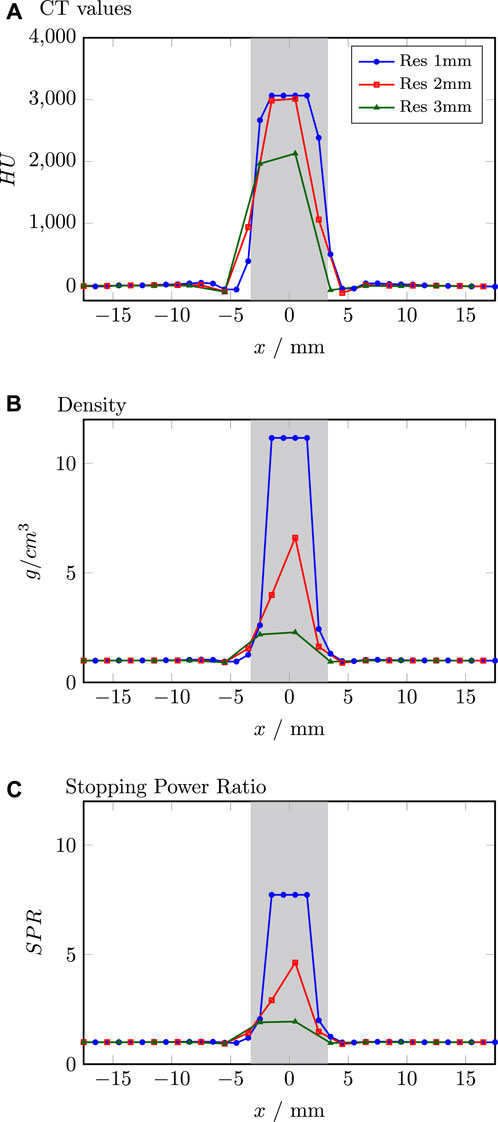
Figure 7. Comparison of CT values (A), density (B) and stopping power ratio (C) for different resolutions extracted from the TPS. Grey shaded area indicates the position of the screw.
Our results indicate that in the absence of a MC simulation-based dose calculation the employed TPS fails to account for the presence of an implant (Figure 4) for photon therapy. However, findings from other groups showed good results with different (not MC simulation-based) dose calculation algorithms near and inside metal implants [7]. What appears to be a clear drawback, can be turned to an advantage in generating treatment plans without dose gradients at the interface between titanium and tissue. Using the CC algorithm during optimization generates a treatment plan which is more robust against small variations in patient positioning. Final dose assessment should be performed using MC simulation to visualize the consequences of the presence of the metal implant. However, before implementing a clinical protocol for handling patients with metal implants, dosimetric measurements with a phantom as presented here are strongly recommended to understand the impact of the used dose calculation engine.
Titanium has five stable isotopes, where 48Ti is the most common one with 73.72%. The production of the scandium isotopes 44Sc, 46Sc and 47Sc via (p,X) reactions as well as the production route 48Ti (p,n) 48V is reported in Michel et al. [39].
A limitation of this work is the low number of repetitions of measurements of individual treatment plans, which has a large impact on calculating the CI of the line profiles. The number of repetitions was a compromise between the investigated treatment plan scenarios and the limited beam time available at the proton facility. Increasing the number of repetitions of the individual treatment plans will further improve the CI and consequently the detection limit of this methodology. The current design of the presented phantom is limited to accommodate implants of up to 3 cm in diameter. This includes implant types such as small plates, rods and dental implants. Other parts such as femoral heads or entire hip prostheses would require a redesign of this version of the phantom.
A direct comparison of the results found in this work for photon beams is challenging as other groups mainly investigated simple static fields. Qualitatively, the dose increase at the tissue-metal interface in the entrance region of the photon beam was also found by other groups [5–7]. The dose distribution within the screw was only investigated by Pawałowski et al. who also found a dose increase within the screw in their experiments [7]. Kamomae et al. investigated the dose distribution near dental implants and found an increased dose compared to the calculated dose of about (10.4
This work clearly demonstrated that dedicated end-2-end phantoms for commissioning TPSs, such as described in this work, will help reduce the uncertainty of dose calculation near metal implants. Further, this methodology should be included in dosimetry audits [23, 24].
5 Conclusion
Our study characterized a dosimetric phantom dedicated to metal implants in photon and proton beams. The employed methodolgy showed a detection limit of 2.2% and 1.7% for photons and protons, respectively. The necessity of such phantoms was demonstrated by the varying characteristics of the dose distribution between the two beam qualities in the vicinity of the implant. Furthermore, depending on the used dose calculation engine the dose distributions differ, and thus experimental verification becomes mandatory. Clear guidelines for radiotherapy patients with metal implants are often lacking. A phantom, as described in this study, can serve as the foundation for dedicated end-2-end phantoms for dosimetric measurements in close proximity to metal implants.
Data availability statement
The raw data supporting the conclusions of this article will be made available by the authors, without undue reservation.
Author contributions
WL: Conceptualization, Data curation, Formal Analysis, Investigation, Methodology, Project administration, Resources, Supervision, Validation, Visualization, Writing–original draft, Writing–review and editing. BK: Conceptualization, Investigation, Methodology, Resources, Supervision, Writing–original draft, Writing–review and editing. JB: Data curation, Formal Analysis, Investigation, Methodology, Validation, Writing–original draft. DG: Formal Analysis, Resources, Writing–original draft, Writing–review and editing. PK: Conceptualization, Data curation, Formal Analysis, Investigation, Methodology, Resources, Writing–original draft, Writing–review and editing.
Funding
The author(s) declare financial support was received for the research, authorship, and/or publication of this article. The financial support by the Austrian Federal Ministry of Labour and Economy, the National Foundation for Research, Technology and Development and the Christian Doppler Research Association is gratefully acknowledged. This project has received funding from the European Union’s Horizon 2020 Marie Skodowska-Curie Actions under Grant Agreement No. 955956.
Acknowledgments
The financial support of the Austrian Ministry of Education, Science, and Research is gratefully acknowledged for providing beam time and research infrastructure at MedAustron. We sincerely thank the MedAustron Department of Radiation Protection, particularly Claudia Lenauer, for conducting the gamma-ray spectroscopy. We furthermore gratefully acknowledge the support of Valentina Francesca Bauer, who assisted the measurements and Adolf Ungerhofer for manufacturing the phantom insert. The authors would also like to thank the IAEA for providing the initial phantom.
Conflict of interest
The authors declare that the research was conducted in the absence of any commercial or financial relationships that could be construed as a potential conflict of interest.
Publisher’s note
All claims expressed in this article are solely those of the authors and do not necessarily represent those of their affiliated organizations, or those of the publisher, the editors and the reviewers. Any product that may be evaluated in this article, or claim that may be made by its manufacturer, is not guaranteed or endorsed by the publisher.
References
1. Kovacs DG, Rechner LA, Appelt AL, Berthelsen AK, Costa JC, Friborg J, et al. Metal artefact reduction for accurate tumour delineation in radiotherapy. Radiother Oncol (2018) 126:479–86. doi:10.1016/j.radonc.2017.09.029
2. Giantsoudi D, Man BD, Verburg J, Trofimov A, Jin Y, Wang G, et al. Metal artifacts in computed tomography for radiation therapy planning: dosimetric effects and impact of metal artifact reduction. Phys Med Biol (2017) 62:R49–R80. doi:10.1088/1361-6560/aa5293
3. Zhang Y, Yu H. Convolutional neural network based metal artifact reduction in x-ray computed tomography. IEEE Trans Med Imaging (2018) 37:1370–81. doi:10.1109/tmi.2018.2823083
4. Kamomae T, Itoh Y, Okudaira K, Nakaya T, Tomida M, Miyake Y, et al. Dosimetric impact of dental metallic crown on intensity-modulated radiotherapy and volumetric-modulated arc therapy for head and neck cancer. J Appl Clin Med Phys (2016) 17:234–45. doi:10.1120/jacmp.v17i1.5870
5. Huang JY, Followill D, Howell RM, Liu X, Mirkovic D, Stingo FC, et al. Approaches to reducing photon dose calculation errors near metal implants. Med Phys (2016) 43:5117–30. doi:10.1118/1.4960632
6. Ojala J, Kapanen M, Sipilä P, Hyödynmaa S, Pitkänen M. The accuracy of Acuros XB algorithm for radiation beams traversing a metallic hip implant — comparison with measurements and Monte Carlo calculations. J Appl Clin Med Phys (2014) 15:162–76. doi:10.1120/jacmp.v15i5.4912
7. Pawałowski B, Ryczkowski A, Panek R, Sobocka-Kurdyk U, Graczyk K, Piotrowski T. Accuracy of the doses computed by the Eclipse treatment planning system near and inside metal elements. Scientific Rep (2022) 12:5974. doi:10.1038/s41598-022-10072-8
8. Liu CW, Cho YB, Magnelli A, Angelov L, Balagamwala EH, Chao ST, et al. The dosimetric impact of titanium implants in spinal SBRT using four commercial treatment planning algorithms. J Appl Clin Med Phys (2023) 24:e14070. doi:10.1002/acm2.14070
9. Gnanasambandam A, Arunai Nambi Raj N, Sollin Selvan K. Effects of metal implants and validation of four treatment planning methods used for radiotherapy dose calculation. Rep Pract Oncol Radiother (2022) 27:821–31. doi:10.5603/rpor.a2022.0098
10. Jia Y, Zhao L, Cheng C, McDonald MW, Das IJ. Dose perturbation effect of metallic spinal implants in proton beam therapy. J Appl Clin Med Phys (2015) 16:333–43. doi:10.1120/jacmp.v16i5.5566
11. Verburg JM, Seco J. Dosimetric accuracy of proton therapy for chordoma patients with titanium implants. Med Phys (2013) 40:071727. doi:10.1118/1.4810942
12. Oancea C, Luu A, Ambrožová I, Mytsin G, Vondráček V, Davídková M. Perturbations of radiation field caused by titanium dental implants in pencil proton beam therapy. Phys Med Biol (2018) 63:215020. doi:10.1088/1361-6560/aae656
13. Kostiukhina N, Georg D, Rollet S, Kuess P, Sipaj A, Andrzejewski P, et al. Advanced Radiation DOSimetry phantom (ARDOS) - a versatile breathing phantom for 4D radiation therapy and medical imaging. Phys Med Biol (2017) 62:8136–53. doi:10.1088/1361-6560/aa86ea
14. Kostiukhina N, Palmans H, Stock M, Georg D, Knäusl B. Dynamic lung phantom commissioning for 4D dose assessment in proton therapy. Phys Med Biol (2019) 64:235001. doi:10.1088/1361-6560/ab5132
15. Tino R, Yeo A, Leary M, Brandt M, Kron T. A systematic review on 3D-printed imaging and dosimetry phantoms in radiation therapy. Tech Cancer Res Treat (2019) 18:153303381987020. doi:10.1177/1533033819870208
16. Brunner J, Langgartner L, Danhel H, Birkfellner W, Richter C, Wagenaar D, et al. Dosimetric characteristics of 3D-printed and epoxy-based materials for particle therapy phantoms. Frontiers (2024) 12. doi:10.3389/fphy.2024.1323788
17. Hranek A, Resch AF, Georg D, Knäusl B. Investigation of the Bragg peak degradation caused by homogeneous and heterogeneous lung tissue substitutes: proton beam experiments and comparison to current clinical dose calculation. Phys Med Biol (2020) 65:245036. doi:10.1088/1361-6560/abc938
18. Taylor PA, Kry SF, Alvarez P, Keith T, Lujano C, Hernandez N, et al. Results from the imaging and radiation oncology core Houston’s anthropomorphic phantoms used for proton therapy clinical trial credentialing. Int J Radiat Oncology*Biology*Physics (2016) 95:242–8. doi:10.1016/j.ijrobp.2016.01.061
19. Izewska J, Wesolowska P, Azangwe G, Followill DS, Thwaites DI, Arib M, et al. Testing the methodology for dosimetry audit of heterogeneity corrections and small MLC-shaped fields: results of IAEA multi-center studies. Acta Oncologica (2016) 55:909–16. doi:10.3109/0284186X.2016.1139180
20. Izewska J, Lechner W, Wesolowska P. Global availability of dosimetry audits in radiotherapy: the IAEA dosimetry audit networks database. Phys Imaging Radiat Oncol (2018) 5:1–4. doi:10.1016/j.phro.2017.12.002
21. Lechner W, Wesolowska P, Azangwe G, Arib M, Alves VGL, Suming L, et al. A multinational audit of small field output factors calculated by treatment planning systems used in radiotherapy. Phys Imaging Radiat Oncol (2018) 5:58–63. doi:10.1016/j.phro.2018.02.005
22. Lye J, Kry S, Shaw M, Gibbons F, Keehan S, Lehmann J, et al. A comparison of IROC and ACDS on-site audits of reference and non-reference dosimetry. Med Phys (2019) 46:5878–87. doi:10.1002/mp.13800
23. Wesolowska P, Georg D, Lechner W, Kazantsev P, Bokulic T, Tedgren AC, et al. Testing the methodology for a dosimetric end-to-end audit of IMRT/VMAT: results of IAEA multicentre and national studies. Acta Oncologica (2019) 58:1731–9. PMID: 31423867. doi:10.1080/0284186X.2019.1648859
24. Kazantsev P, Lechner W, Gershkevitsh E, Clark CH, Venencia D, Dyk JV, et al. IAEA methodology for on-site end-to-end IMRT/VMAT audits: an international pilot study. Acta Oncologica (2020) 59:141–8. PMID: 31746249. doi:10.1080/0284186X.2019.1685128
25. Kazantsev P, Wesolowska P, Bokulic T, Falowska-Pietrzak O, Repnin K, Dimitriadis A, et al. The IAEA remote audit of small field dosimetry for testing the implementation of the TRS-483 code of practice. Med Phys (2024). doi:10.1002/mp.17109
26. Kuess P, Böhlen TT, Lechner W, Elia A, Georg D, Palmans H. Lateral response heterogeneity of Bragg peak ionization chambers for narrow-beam photon and proton dosimetry. Phys Med Biol (2017) 62:9189–206. doi:10.1088/1361-6560/aa955e
27. Stock M, Georg D, Ableitinger A, Zechner A, Utz A, Mumot M, et al. The technological basis for adaptive ion beam therapy at MedAustron: status and outlook. Z für Medizinische Physik (2018) 28:196–210. doi:10.1016/j.zemedi.2017.09.007
28. Zhang R, Newhauser WD. Calculation of water equivalent thickness of materials of arbitrary density, elemental composition and thickness in proton beam irradiation. Phys Med Biol (2009) 54:1383–95. doi:10.1088/0031-9155/54/6/001
29. Khachonkham S, Dreindl R, Heilemann G, Lechner W, Fuchs H, Palmans H, et al. Characteristic of EBT-XD and EBT3 radiochromic film dosimetry for photon and proton beams. Phys Med Biol (2018) 63:065007. doi:10.1088/1361-6560/aab1ee
30. IAEA. Absorbed dose determination in external beam radiotherapy. Vienna, Austria: International Atomic Energy Agency (2024). doi:10.61092/iaea.ve7q-y94k
31. IAEA. Dosimetry of small static fields used in external beam radiotherapy. Vienna, Austria: International Atomic Energy Agency (2017). Technical Report Series No. 483.
32. Palmer AL, Dimitriadis A, Nisbet A, Clark CH. Evaluation of gafchromic ebt-xd film, with comparison to ebt3 film, and application in high dose radiotherapy verification. Phys Med Biol (2015) 60:8741–52. doi:10.1088/0031-9155/60/22/8741
33. Niroomand-Rad A, Chiu-Tsao ST, Grams MP, Lewis DF, Soares CG, Van Battum LJ, et al. Report of AAPM task group 235 radiochromic film dosimetry: an update to TG-55. Med Phys (2020) 47:5986–6025. doi:10.1002/mp.14497
34. Resch AF, Heyes PD, Fuchs H, Bassler N, Georg D, Palmans H. Dose-rather than fluence-averaged LET should be used as a single-parameter descriptor of proton beam quality for radiochromic film dosimetry. Med Phys (2020) 47:2289–99. doi:10.1002/mp.14097
35. Ruangchan S, Knäusl B, Fuchs H, Georg D, Clausen M. Physica Medica Experimental benchmarking of RayStation proton dose calculation algorithms inside and outside the target region in heterogeneous phantom geometries. Physica Med (2020) 76:182–93. doi:10.1016/j.ejmp.2020.07.010
36. Yepes P, Adair A, Grosshans D, Mirkovic D, Poenisch F, Titt U, et al. Comparison of Monte Carlo and analytical dose computations for intensity modulated proton therapy. Phys Med Biol (2018) 63:045003. doi:10.1088/1361-6560/aaa845
37. Fracchiolla F, Engwall E, Janson M, Tamm F, Lorentini S, Fellin F, et al. Clinical validation of a GPU-based Monte Carlo dose engine of a commercial treatment planning system for pencil beam scanning proton therapy. Physica Med (2021) 88:226–34. doi:10.1016/j.ejmp.2021.07.012
38. Rousselle A, Amelot A, Thariat J, Jacob J, Mercy G, De Marzi L, et al. Metallic implants and CT artefacts in the CTV area: where are we in 2020? Cancer Radiotherapie (2020) 24:658–66. doi:10.1016/j.canrad.2020.06.022
39. Michel R, Bodemann R, Busemann H, Dauke R, Gloris M, Lange H, et al. Cross sections for the production of residual nuclides by low- and medium-energy protons from the target elements C, N, O, Mg, Al, Si, Ca, Ti, V, Mn, Fe, Co, Ni, Cu, Sr, Y, Zr, Nb, Ba and Au. Nucl Instr Methods Phys Res B (1997) 129:153–93. doi:10.1016/s0168-583x(97)00213-9
Keywords: proton and photon radiotherapy, radiation oncology, dosimetry, phantom design, metal implants, dose calculation accuracy
Citation: Lechner W, Knäusl B, Brunner J, Georg D and Kuess P (2024) A phantom for 2D dose measurements in the vicinity of metal implants for photon and proton beams. Front. Phys. 12:1433208. doi: 10.3389/fphy.2024.1433208
Received: 15 May 2024; Accepted: 12 July 2024;
Published: 02 August 2024.
Edited by:
Huidong Yang, University of Vienna, AustriaReviewed by:
Salvador García-Pareja, Regional University Hospital of Malaga, SpainMoshi Geso, RMIT University, Australia
Copyright © 2024 Lechner, Knäusl, Brunner, Georg and Kuess. This is an open-access article distributed under the terms of the Creative Commons Attribution License (CC BY). The use, distribution or reproduction in other forums is permitted, provided the original author(s) and the copyright owner(s) are credited and that the original publication in this journal is cited, in accordance with accepted academic practice. No use, distribution or reproduction is permitted which does not comply with these terms.
*Correspondence: Wolfgang Lechner, d29sZmdhbmcubGVjaG5lckBtZWR1bml3aWVuLmFjLmF0