 Huiwen Li
 Haifeng Gao
 Jianguo Liang1
 Changjun Zheng
- 1College of Mechanical and Vehicle Engineering, Taiyuan University of Technology, Taiyuan, China
- 2Shanxi-Zheda Institute of Advanced Materials and Chemical Engineering, Taiyuan, China
- 3Institute of Sound and Vibration Research, Hefei University of Technology, Hefei, Anhui, China
The paper presents a topology optimization methodology for 2D elastodynamic problems using the boundary element method (BEM). The topological derivative is derived based on the variation method and the adjoint variable method. The level set method is employed for the representation of the material domain and voids within a specified design domain. Thus, the boundaries can easily be generated, following the zero isocontour of the level set function. Numerical implementation is carried out to demonstrate the effectiveness of the proposed topology optimization methodology in wave isolation and waveguide problems.
1 Introduction
The problem of vibration control with artificial structures has been an important issue in aerospace [1,2], vehicle design [3], civil engineering [4], and vibration pollution [5]. The suppression, absorption, or waveguide of elastic waves are considered effective tools for the vibration problems which affect the safety, reliability, and stability of equipment. Passive vibration control approaches are widely applied in engineering problems due to their simple design and low cost. Various passive vibration control structures are designed and artificially manufactured to meet the requirements of vibration-related engineering problems. Phononic crystals and metamaterials are adopted for mechanical filters and vibration isolators due to their band gaps, which can strictly forbid the propagation of acoustic or elastic waves in a certain range of frequency [6]. An open trench and wave-impeding block-combined vibration isolation barrier is an effective way of protecting equipment or buildings from environmental vibration sources [7]. Waveguide absorbers are designed to extract elastic wave energy, dissipating it with artificial spiral acoustic black holes [8]. The narrow control frequency range, which is considered a drawback of passive systems, is improved by invoking nonlinear dynamic theories [9].
The numerical simulation method is an effective and efficient approach which can significantly reduce the cost of the design or analysis of vibration problems. Moreover, topology optimization methods based on numerical techniques are developed to acquire the desired structures with prescribed objectives and constraints. Early efforts on structural design through topology optimization methods include previous research works [10, 11]. Several widely used topology optimization algorithms, such as the homogenization method [12], the solid isotropic material with penalization (SIMP) method [13–16], the evolutionary structural optimization (ESO) method [17–20], the moving morphable component (MMC) method [21–24], and level set-based methods [25–27], have gained great attraction in research investigations. Liu et al. carried out the topology optimization of attached piezoelectric actuators of thin-walled structures for both vibration control and manufacturing constraints using a K-means clustering method [28]. Liu et al. analyzed the topology optimization of high-frequency vibration of solid structures using the energy finite element method (EFEM), which allows less calculation and a clear distribution of the energy density [29]. Yan et al. optimized the distribution of damping material in shell structures to minimize the residual vibration using SIMP, and the sensitivity was obtained using the adjoint method [30]. For vibration isolation problems, Zhou et al. developed a multi-objective and multi-level optimization method for the design of supporting structures and loci of isolators [31]. The topology optimization of one-material structures for displacement antiresonances at frequencies of interest is carried out by Silva et al [32]. These techniques allow the evolution of the topology without the need to perform remeshing, and most of the topological numerical methods have been implemented relying on the finite element method (FEM), which usually easily leads to checkboard patterns and grayscale problems.
However, the quantities on the boundary of the analyzing domain are engineers’ concern in most cases for vibration isolation or waveguide problems. Unlike the finite element method, which involves substantial computational and memory expenditure during mesh generation, the boundary element method merely discretizes the model boundaries. This method offers advantages such as dimension reduction, high computational accuracy, and constant elements for modeling. Thus, the combination of the LSM with the boundary element method (BEM) provides an easy numerical updating process for the topology evolution since the zero isosurface/isoline of the level set function (LSF), which represents the boundaries emerging in the design domain, has the same dimension as boundary elements’. The simplicity of the pre-process and post-process in the generation of boundary elements makes the combination approach a promising tool for topology optimization problems. Jing et al. presented topology optimization for maximizing the total potential energy of thermal problems with the level set method and BEM [33]. Chen et al. optimized the topology and shape of sound-absorbing materials through isogeometric BEM [34–37] and optimized the topology of vibrating structures that interacted with acoustic waves through isogeometric FEM–BEM [38, 39], which reduced the radiated sound power and improved optimization efficiency. Isakari et al. developed topology optimization for acoustic-elastic coupled problems by employing a fast BEM–FEM coupled solver [40]. Oliveira et al. extended the isogeometric BEM to topology optimization based on the LSM for elastic static problems [41]. Matsushima et al. solved the defect detection inverse problems using the BEM [42], and Tang et al. considered the objective function, which includes the tangential derivative of displacements for cavity detection [43]. The application of the BEM-based topology method to the design of vibration control structures, however, is not sufficiently investigated. The suppression or magnification of the vibration amplitudes at certain frequencies can effectively manipulate the elastic wave propagation.
In view of the aforementioned advantages of the proposed methodology, the present work aims to extend the BEM and level set-based topology optimization to elastodynamic problems for the design of vibration control structures. The paper first introduces the formulas for the boundary integral equation and its discretization, and then, the topology optimization algorithm, which includes the formulation of the topology derivative and evolution equation, is presented. Numerical implementations are finally shown to demonstrate the effectiveness of the method for vibration isolation and waveguide applications.
2 Boundary element method for 2D elastodynamic problems
The linear elastodynamic problems are governed by the equation written in the form of displacement [44]:
where y denotes a point in the medium domain Ω and qj denotes the xj component of the displacement vector in Eq. 1. C1 and C2 are the P wave speed and S wave speed, respectively, which are written as
where E is the Young’s modulus, ν is the Poisson’s ratio, and ρ is the density of the medium, as shown in Eqs 2, 3.
Let us rewrite the governing equation by removing the time-related terms due to the harmonic vibration of linear elastic structures. Then, we have
where ω is the circular frequency and Q is a complex number that denotes the vibration displacement, including amplitude and phase. The boundary integral equation (BIE) form of Eq. 4 is written as
where ckl is the free term of the BIE and the kernels Ψij (y, ys, ω) and Φij (y, ys, ω) are known as displacement and traction fundamental solutions for 2D elastodynamic problems, respectively:
where δij is Kronecker’s delta, r is the distance between ys and y, and ni is the unit outward normal vector to the boundary in Eqs 6, 7.
where i is the imaginary unit and Kj denotes the modified Bessel functions of order j in Eqs 8, 9.
In order to evaluate the topological derivative, the expression of the stress is required:
where yin is a point in Ω and Dkij and Skij are three-order tensors in Eq. 10.
Discretizing Eq. 5 with N constant boundary elements, we obtain a linear equation as follows:
where
Let i in Eq. 11 vary from 1 to N; then, we obtain a system of 2N linear algebraic equations as shown in Eq. 12.
where H and G are 2N × 2N matrices, respectively, and Q and
3 Topology optimization algorithm
3.1 Topological derivative
To carry out the topology optimization for a continuous medium, the sensitivity of the objective function with respect to the change in topology is needed. As shown in Figure 1, the objective function J is defined on Γf, which is a portion of the boundary of domain Ωϵ. The sensitivity can be considered the topological derivative
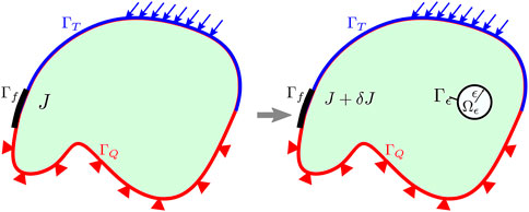
Figure 1. Variation in the objective function according to the removal of an infinitesimal cavity Ωϵ.
Usually, the objective function is defined as a real value on the objective boundary Γf:
As the cavity Ωϵ is generated,
Subtracting Eq. 13 from Eq. 14,
To evaluate
where δQk on Γϵ cannot be acquired easily in Eq. 16. Thus, we introduce an adjoint field of
and substituting the boundary conditions in Eq. 21 and 17, we have
Assuming that Γf includes ΓQ and ΓT,
Considering the adjoint field as the Lagrange multiplier, we obtained
In order to avoid the evaluation of δQk, we can construct the adjoint field
where the terms related to
Let us consider the center of Ωϵ as point y, and the topological derivative at the point y can be calculated by taking the limit, as shown in Eq. 24.
The formula for
where λ and μ are Lamé constants, which are given in Eq. 26.
3.2 LSM
The elastic material medium is defined by the LSF ϕ in the design domain D. As shown in Figure 2, for a point y in D, the medium and void are defined using the value of ϕ(y) as shown in Eq. 27.
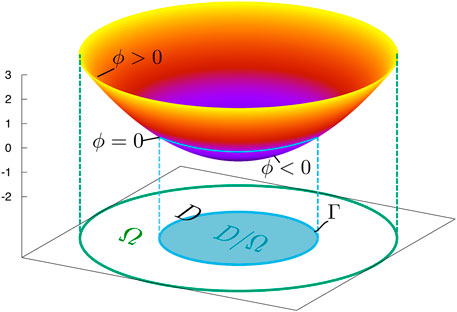
Figure 2. Medium domain Ω defined by the LSF implicitly.
The optimization problem for minimizing the objective function
subject to
where α is the Lagrange multiplier in Eq. 29.
where G is the volume constraint which controls the size of the material area, χϕ is the characteristic function, and Gmax is the admissible upper limit of the material area in Eq. 30.
Let us rewrite the objective function
where λ is the Lagrange multiplier for the area constraint G in Eq. 31. According to the Karush–Kuhn–Tucker (KKT) condition, the optimal solution of the optimization problem is shown in Eq. 32.
Let us introduce the reaction-diffusion equation:
where
4 Numerical implementation
4.1 Example 1: vibration isolation at y-direction
Let us consider the structure depicted in Figure 3, where we can find the excitation force F = 1.0 × 10⁶ N with the frequency at 230 Hz and the objective function
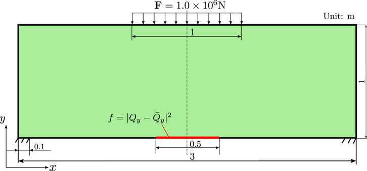
Figure 3. Definition of the boundary conditions for example 1.
The intermediate results at steps 8, 10, 12, 13, 20, and 30 are presented in Figure 4. A small cavity is generated from step 8 and disappears at step 12; however, the cavities appear again at step 13 and reduce the vibration amplitude at the objective boundary. The convergence of the objective function and the area is shown in Figure 5. The convergence curve of the objective function shows the change in the vibration amplitude at the objective boundary, and it can be seen that the value of the objective function increases at step 8 and decreases rapidly from step 13. The increase in the objective function implies that the starting point of the topological derivative may just lose a solution and look for the next solution. Thus, one can find that the objective function increases first and then decreases rapidly. Finally, the objective function becomes smaller compared with it at the beginning. The optimal structure leads to a reduction in the vibration amplitude from 0.36 to 0.09 (normalized).
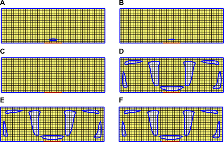
Figure 4. Intermediate optimized solutions during the iteration for example 1: a) Step 8, b) Step 10, c) Step 12, d) Step 13, e) Step 20, and f) Step 30.
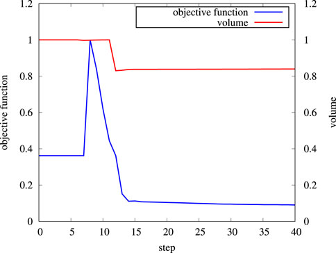
Figure 5. Convergence of the objective function and area for example 1.
Let us consider the response problem of the optimized structure under the excitation frequency range [100, 500] Hz. As shown in Figure 6, the objective function, which implies the vibration amplitude at the objective boundary, presents a value of 10–2 at the optimizing frequency of 230 Hz before the optimization. However, the objective function decreases to approximately 10–7 after the optimization. The frequency sweep analysis implies that the optimized structure is effective for the isolation of vibration in the vicinity of 230 Hz, when the displacement response along the y-direction of the bottom of the rectangular structure is considered.
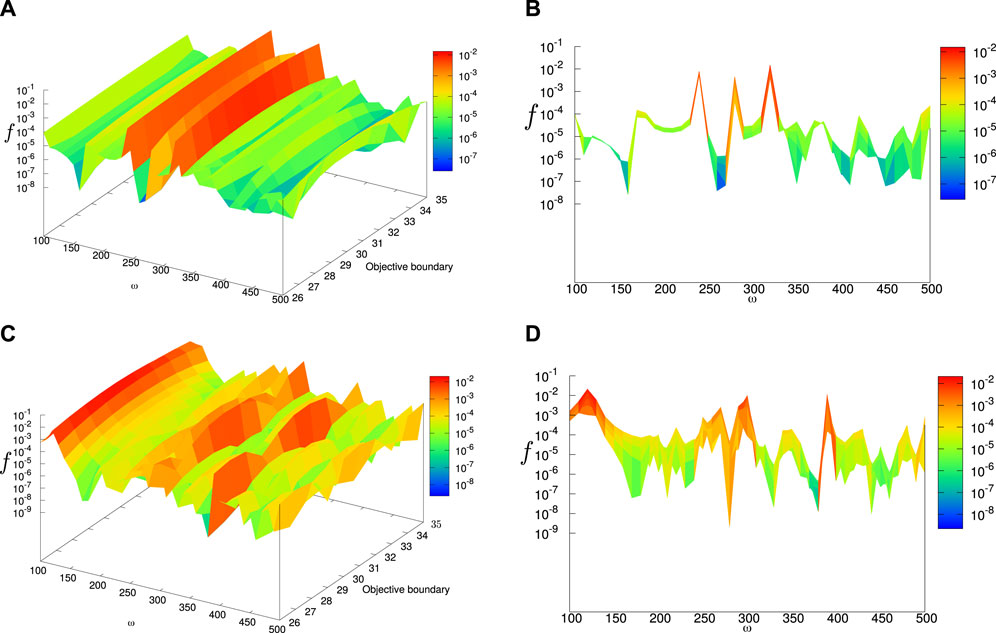
Figure 6. Objective function response of the structure before and after optimization for example 1 as ω varies from 100 Hz to 500 Hz: a) the vibration amplitude at objective boundary with frequency sweep from 100 Hz to 500 Hz before optimization. b) The vibration amplitude at objective boundary with frequency sweep from 100 Hz to 500 Hz before optimization (f–ω plane). c) The vibration amplitude at objective boundary with frequency sweep from 100 Hz to 500 Hz after optimization. d) The vibration amplitude at objective boundary with frequency sweep from 100 Hz to 500 Hz after optimization (f–ω plane).
4.2 Example 2: vibration isolation at x-direction
In elastodynamic problems, when a structure is subjected to excitation forces, both longitudinal and transverse waves are generated inside the structure. At positions perpendicular to the direction of the excitation force, longitudinal waves in the structure are the main influencing factor of the magnitude of the external normal amplitude, while at positions parallel to them, transverse waves in the structure are the main influencing factor of the magnitude of the external normal amplitude. The model optimization in example 1 reduces the amplitude at the position perpendicular to the direction of the excitation force. Therefore, this example studies the amplitude magnitude at the position parallel to the excitation force in the structure.
Example 2 employs the model presented in Figure 7, where the objective boundaries are specified on the left and right sides of the square design domain uniformly. The material constants are given the same as those in example 1. The displacements along the x-direction are controlled through the definition of the objective function
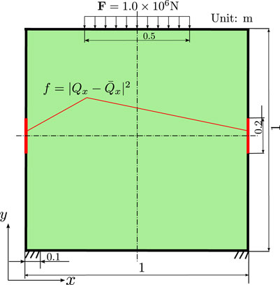
Figure 7. Definition of the boundary conditions for example 2.
Figure 8 shows the convergence of the objective function and the area during the calculation. The objective function decreases to 0.029 from step 15 and converges to the vicinity of 0.027. A cavity is generated at step 8 and enlarged with the evolution of the LSF. Furthermore, from step 15, the generated cavity almost remains unchanged until step 40, and the results of steps 20 and 30 are also presented in Figure 9. The reduction in the objective function demonstrates the effectiveness of the vibration suppression of the amplitude along the x-direction at the objective boundary. Moreover, the reduction in the vibration also happens at the neighborhood of 250 Hz according to the results of frequency sweep. The excitation frequency of 250 Hz is near the second natural frequency of the original design domain, and the peaks of the objective function in the frequency sweep analysis are shifted after optimization, as shown in Figure 10. The objective function with
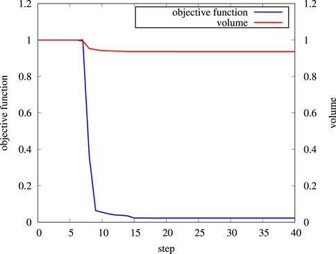
Figure 8. Convergence of the objective function and area for example 2.
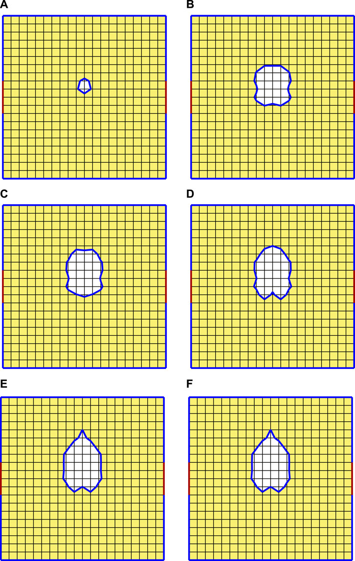
Figure 9. Intermediate optimized solutions during the iteration for example 2: a) Step 8, b) Step 9, c) Step 10, d) Step 11, e) Step 20, and f) Step 30.
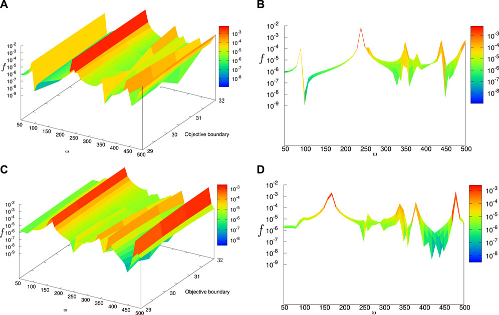
Figure 10. Objective function response of the structure before and after optimization for example 2 as ω varies from 50 Hz to 500 Hz: a) the vibration amplitude at objective boundary with frequency sweep from 50 Hz to 500 Hz before optimization. b) The vibration amplitude at objective boundary with frequency sweep from 50 Hz to 500 Hz before optimization (f–ω plane). c) The vibration amplitude at objective boundary with frequency sweep from 50 Hz to 500 Hz after optimization. d) The vibration amplitude at objective boundary with frequency sweep from 50 Hz to 500 Hz after optimization (f–ω plane).
4.3 Example 3: vibration enhanced at certain boundary
Another application of the proposed method is to enhance the vibration amplitude at a certain boundary. The model depicted in Figure 11 has the objective boundary defined on the right side of a square design domain asymmetrically. The material constants are the same as in the previous examples,’ and the excitation frequency is set at 150 Hz. The initial Qx values at the objective boundary (from elements 32–35) lie between 1.09 × 10⁻³ m and 1.14 × 10⁻³ m. In order to guide the vibration energy to the objective boundary and strengthen the vibration amplitude, the objective function is defined as
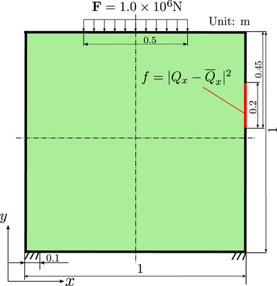
Figure 11. Definition of the boundary conditions for example 3.
The reduction in the objective function can be observed in Figure 12, and it implies that the displacement is increasing. From step 16, the objective function decreases almost by 80%, and the cavity emerges from step 8, as shown in Figure 13. The cavity expands along with the iteration of LSF, which becomes steady from step 15. It can be seen that the generated cavity is located near the objective boundary, which leads to the strengthening of the vibration. The responses of both the objective function and displacement Qx are displayed in Figure 14, where one can find that the order of the magnitude of the vibration amplitude along the x-direction is enlarged from 10–3 to 10–2. Figure 14 also shows that the natural frequencies are modified by the change in topology. The detail of the vibration amplitude change at 150 Hz is presented in Table 1, where one can also find the change in the objective function.
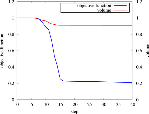
Figure 12. Convergence of the objective function and area for example 2.
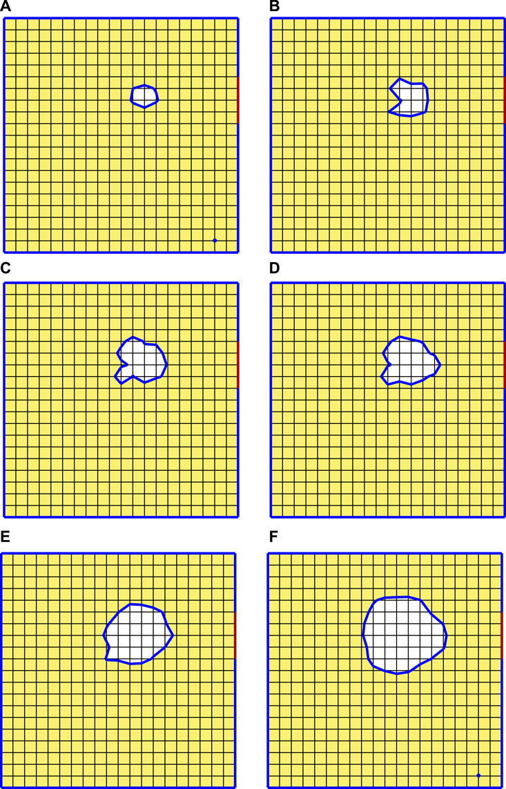
Figure 13. Intermediate optimized solutions during the iteration for example 3: a) Step 8, b) Step 9, c) Step 10, d) Step 11, e) Step 12, and f) Step 16.
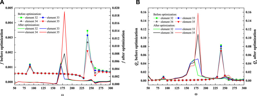
Figure 14. Responses of the objective function and vibration amplitude at the objective boundary of the structure before and after optimization for example 3 as ω varies from 50 Hz to 300 Hz: a) responses of the objective function and b)responses of the vibration amplitude.
Table 1. Values of f and Qx at 150 Hz for example 3.
Example 3 shows that the proposed topology optimization method can also be applied to vibration-enhancing problems, and the elastic wave can be guided to a certain portion of the boundary. Furthermore, τ affects the final optimized results, as shown in Figure 15, where the results at step 40 with τ = 0.1, τ = 0.3, τ = 0.7, and τ = 0.9 are presented, and it is found that the results can be manipulated by changing the curvature of LSF by defining different values of τ. The manufacturing requirement can be satisfied by choosing an appropriate value of τ.
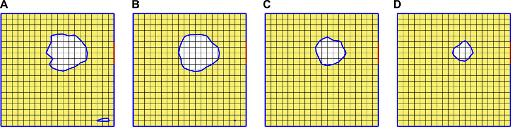
Figure 15. Optimized results with different τ values for example 3: a) τ = 0.1, b) τ = 0.3, c) τ = 0.7, and d) τ = 0.9.
5 Conclusion
The work is undertaken to propose a topology optimization methodology for 2D elastodynamic problems using BEM. The topological derivative obtained using the adjoint viable method includes the stress tensors of both the original and adjoint fields. The topology optimization methodology can generate clear boundaries due to the implicit expression of the voids by the LSF. Fortunately, the boundary-only discretization, which is one of the features of the BEM, leads to an easy rebuild of the numerical models in the iteration process. Several numerical examples with different optimization purposes are presented. The results of the simulations show that the proposed methodology is effective for structure topology design in the application of vibration isolation and waveguide problems.
Data availability statement
The original contributions presented in the study are included in the article/Supplementary material; further inquiries can be directed to the corresponding author.
Author contributions
HL: writing–original draft and writing–review and editing. HG: writing–original draft and writing–review and editing. JL: writing–review and editing. ZL: writing–review and editing. HX: writing–review and editing. CZ: writing–review and editing.
Funding
The author(s) declare that financial support was received for the research, authorship, and/or publication of this article. This work was supported by the Fundamental Research Program of Shanxi Province (grant no. 202203021221053), the National Natural Science Foundation of China (grant nos. 12272117 and 52075361), the Shanxi-Zheda Institute of Advanced Materials and Chemical Engineering (grant no. 2022SX-TD021), the Lvliang Science and Technology Guidance Special Key R&D Project (grant no. 2022XDHZ08), the Major Science and Technology Project of Shanxi Province (grant no. 20201102003), and the Key Research and Development Projects in Shanxi Province (grant no. 201903D421030).
Acknowledgments
The authors wish to express their appreciation to the reviewers for their helpful suggestions, which greatly improved the presentation of this paper.
Conflict of interest
The authors declare that the research was conducted in the absence of any commercial or financial relationships that could be construed as a potential conflict of interest.
Publisher’s note
All claims expressed in this article are solely those of the authors and do not necessarily represent those of their affiliated organizations, or those of the publisher, the editors, and the reviewers. Any product that may be evaluated in this article, or claim that may be made by its manufacturer, is not guaranteed or endorsed by the publisher.
References
1. Kamesh D, Pandiyan R, Ghosal A Modeling, design and analysis of low frequency platform for attenuating micro-vibration in spacecraft. J Sound Vibration (2010) 329:3431–50. doi:10.1016/j.jsv.2010.03.008
2. Yan B, Wang K, Kang C-X, Zhang X-N, Wu C-Y Self-sensing electromagnetic transducer for vibration control of space antenna reflector. IEEE/ASME Trans Mechatronics (2017) 22:1944–51. doi:10.1109/TMECH.2017.2712718
3. Huang P, Yao Y, Xiu W, Wu J, Geng D, Yang Z, et al. Vibration modelling and testing of off-road vehicle incorporating coupled roll and pitch vibrations. Biosyst Eng (2024) 240:111–22. doi:10.1016/j.biosystemseng.2024.02.006
4. Xiao P, Miao L, Zheng H, Lei L Low frequency vibration reduction bandgap characteristics and engineering application of phononic-like crystal metaconcrete material. Construction Building Mater (2024) 411:134734. doi:10.1016/j.conbuildmat.2023.134734
5. Fan X, Li L, Zhao L, He H, Zhang D, Ren Z, et al. Environmental noise pollution control of substation by passive vibration and acoustic reduction strategies. Appl Acoust (2020) 165:107305. doi:10.1016/j.apacoust.2020.107305
6. Rifaie MA, Abdulhadi H, Mian A Advances in mechanical metamaterials for vibration isolation: a review. Adv Mech Eng (2022) 14:168781322210828. doi:10.1177/16878132221082872
7. Cao X, Zhou F, Liu J, Ma Q Experimental study and numerical analysis for vibration isolation performance on open trench and wave impeding block combined vibration isolation barrier. Soil Dyn Earthquake Eng (2024) 177:108418. doi:10.1016/j.soildyn.2023.108418
8. Park S, Lee JY, Jeon W Vibration damping of plates using waveguide absorbers based on spiral acoustic black holes. J Sound Vibration (2022) 521:116685. doi:10.1016/j.jsv.2021.116685
9. Xu X, Barnhart MV, Fang X, Wen J, Chen Y, Huang G A nonlinear dissipative elastic metamaterial for broadband wave mitigation. Int J Mech Sci (2019) 164:105159. doi:10.1016/j.ijmecsci.2019.105159
10. Sigmund O, Maute K Topology optimization approaches:a comparative review. Struct Multidisciplinary Optimization (2013) 48:1031–55. doi:10.1007/s00158-013-0978-6
11. Huang X, Xie Y-M A further review of eso type methods for topology optimization. Struct multidisciplinary optimization (2010) 41:671–83. doi:10.1007/s00158-010-0487-9
12. Bendsøe MP, Kikuchi N Generating optimal topologies in structural design using a homogenization method. Computer Methods Appl Mech Eng (1988) 71:197–224. doi:10.1016/0045-7825(88)90086-2
13. Bendsøe MP Optimal shape design as a material distribution problem. Struct optimization (1989) 1:193–202. doi:10.1007/BF01650949
14. Rozvany GIN, Zhou M, Birker T Generalized shape optimization without homogenization. Struct optimization (1992) 4:250–2. doi:10.1007/BF01742754
15. Bendsøe MP, Sigmund O Material interpolation schemes in topology optimization. Archive Appl Mech (1999) 69:635–54. doi:10.1007/s004190050248
16. Groen JP, Langelaar M, Sigmund O, Ruess M Higher-order multi-resolution topology optimization using the finite cell method. Int J Numer Methods Eng (2017) 110:903–20. doi:10.1002/nme.5432
17. Xie Y, Steven G A simple evolutionary procedure for structural optimization. Comput Structures (1993) 49:885–96. doi:10.1016/0045-7949(93)90035-C
18. Querin O, Steven G, Xie Y Evolutionary structural optimisation (eso) using a bidirectional algorithm. Eng Computations (1998) 15:1031–48. doi:10.1108/02644409810244129
19. Huang X, Xie Y Convergent and mesh-independent solutions for the bi-directional evolutionary structural optimization method. Finite Elem Anal Des (2007) 43:1039–49. doi:10.1016/j.finel.2007.06.006
20. Li Y Topology optimization of compliant mechanisms based on the beso method. Melbourne (Australia): Royal Melbourne Institute of Technology University (2014). Dissertation.
21. Guo X, Zhang W, Zhong W Doing topology optimization explicitly and geometrically - a new moving morphable components based framework. J Appl Mech (2014) 81:081009. doi:10.1115/1.4027609
22. Zhang W, Chen J, Zhu X, Zhou J, Xue D, Lei X, et al. Explicit three dimensional topology optimization via moving morphable void (mmv) approach. Computer Methods Appl Mech Eng (2017) 322:590–614. doi:10.1016/j.cma.2017.05.002
23. Zhang W, Song J, Zhou J, Du Z, Zhu Y, Sun Z, et al. Topology optimization with multiple materials via moving morphable component (mmc) method. Int J Numer Methods Eng (2018) 113:1653–75. doi:10.1002/nme.5714
24. Zhang W, Li D, Kang P, Guo X, Youn S-K Explicit topology optimization using iga-based moving morphable void (mmv) approach. Computer Methods Appl Mech Eng (2020) 360:112685. doi:10.1016/j.cma.2019.112685
25. Wang MY, Wang X, Guo D A level set method for structural topology optimization. Computer Methods Appl Mech Eng (2003) 192:227–46. doi:10.1016/S0045-7825(02)00559-5
26. Liu J, Ma YS 3d level-set topology optimization: a machining feature-based approach. Struct Multidisciplinary Optimization (2015) 52:563–82. doi:10.1007/s00158-015-1263-7
27. Chung H, Amir O, Kim HA Level-set topology optimization considering nonlinear thermoelasticity. Computer Methods Appl Mech Eng (2020) 361:112735. doi:10.1016/j.cma.2019.112735
28. Liu Y, Xiao D Shape feature controlled topology optimization of attached piezoelectric actuators for vibration control of thin-walled smart structures. Appl Math Model (2023) 120:575–94. doi:10.1016/j.apm.2023.03.018
29. Liu H, Zhang Z, Li B, Xie M, Hong J, Zheng S Topology optimization of high frequency vibration problems using the efem-based approach. Thin-Walled Structures (2021) 160:107324. doi:10.1016/j.tws.2020.107324
30. Yan K, Cheng GD, Wang BP Topology optimization of damping layers in shell structures subject to impact loads for minimum residual vibration. J Sound Vibration (2018) 431:226–47. doi:10.1016/j.jsv.2018.06.003
31. Zhou P, Du J, Lü Z Simultaneous topology optimization of supporting structure and loci of isolators in an active vibration isolation system. Comput Structures (2018) 194:74–85. doi:10.1016/j.compstruc.2017.09.006
32. Silva OM, Neves MM, Lenzi A On the use of active and reactive input power in topology optimization of one-material structures considering steady-state forced vibration problems. J Sound Vibration (2020) 464:114989. doi:10.1016/j.jsv.2019.114989
33. Jing G, Jia J, Xiang J Level set-based bem topology optimization method for maximizing total potential energy of thermal problems. Int J Heat Mass Transfer (2022) 182:121921. doi:10.1016/j.ijheatmasstransfer.2021.121921
34. Chen L, Lu C, Lian H, Liu Z, Zhao W, Li S, et al. Acoustic topology optimization of sound absorbing materials directly from subdivision surfaces with isogeometric boundary element methods. Computer Methods Appl Mech Eng (2020) 362:112806. doi:10.1016/j.cma.2019.112806
35. Chen L, Lian H, Natarajan S, Zhao W, Chen X, Bordas S Multi-frequency acoustic topology optimization of sound-absorption materials with isogeometric boundary element methods accelerated by frequency-decoupling and model order reduction techniques. Computer Methods Appl Mech Eng (2022) 395:114997. doi:10.1016/j.cma.2022.114997
36. Lu C, Chen L, Luo J, Chen H Acoustic shape optimization based on isogeometric boundary element method with subdivision surfaces. Eng Anal Boundary Elem (2023) 146:951–65. doi:10.1016/j.enganabound.2022.11.010
37. Chen L, Lian H, Liu Z, Chen H, Atroshchenko E, Bordas S Structural shape optimization of three dimensional acoustic problems with isogeometric boundary element methods. Computer Methods Appl Mech Eng (2019) 355:926–51. doi:10.1016/j.cma.2019.06.012
38. Chen L, Lian H, Dong H-W, Yu P, Jiang S, Bordas SP Broadband topology optimization of three-dimensional structural-acoustic interaction with reduced order isogeometric fem/bem. J Comput Phys (2024) 509:113051. doi:10.1016/j.jcp.2024.113051
39. Chen L, Lian H, Liu Z, Gong Y, Zheng C, Bordas S Bi-material topology optimization for fully coupled structural-acoustic systems with isogeometric fem–bem. Eng Anal Boundary Elem (2022) 135:182–95. doi:10.1016/j.enganabound.2021.11.005
40. Isakari H, Kondo T, Takahashi T, Matsumoto T A level-set-based topology optimisation for acoustic-elastic coupled problems with a fast bem-fem solver. Computer Methods Appl Mech Eng (2017) 315:501–21. doi:10.1016/j.cma.2016.11.006
41. Oliveira HL, de Castro e Andrade H, Leonel ED An isogeometric boundary element approach for topology optimization using the level set method. Appl Math Model (2020) 84:536–53. doi:10.1016/j.apm.2020.03.047
42. Matsumoto KMIT An application of topology optimisation to defect identification in two-dimensional elastodynamics with the bem and h-matrix method. Int J Comput Methods Exp Measurements (2018) 6:73. doi:10.2495/CMEN-V6-N6-1033-1042
43. Tang P, Matsushima K, Isakari H, Takahshi T, Matsumoto T An adjoint variable method for the topological derivative of the tangent derivative of boundary data. Trans JASCOME (2020) 20:19–201219.
44. Gao H, Matsumoto T, Takahashi T, Isakari H Investigation of finite/infinite unidirectional elastic phononic plates by bem. Eng Anal Boundary Elem (2014) 40:93–103. doi:10.1016/j.enganabound.2013.12.003
46. Tang P Level-set based topology optimization with objective functional of tangential derivatives of boundary displacement for two-dimensional elastodynamics problem. Dissertation. Nagoya (Japan): Nagoya University (2021).
Keywords: boundary element method, topology optimization, level set method, elastodynamic problems, vibration control
Citation: Li H, Gao H, Liang J, Li Z, Xu H and Zheng C (2024) A level set based topology optimization for elastodynamic problems using BEM. Front. Phys. 12:1426846. doi: 10.3389/fphy.2024.1426846
Received: 02 May 2024; Accepted: 29 May 2024;
Published: 16 July 2024.
Edited by:
Pei Li, University of Southern Denmark, DenmarkReviewed by:
Xiangsheng Gao, Beijing University of Technology, ChinaJinqiang Li, Harbin Engineering University, China
Zhiwei Hao, Harbin Institute of Technology, China
Copyright © 2024 Li, Gao, Liang, Li, Xu and Zheng. This is an open-access article distributed under the terms of the Creative Commons Attribution License (CC BY). The use, distribution or reproduction in other forums is permitted, provided the original author(s) and the copyright owner(s) are credited and that the original publication in this journal is cited, in accordance with accepted academic practice. No use, distribution or reproduction is permitted which does not comply with these terms.
*Correspondence: Haifeng Gao, Z2FvaGFpZmVuZ0B0eXV0LmVkdS5jbg==