 Marie Wegner
 Jonte Schmiech1
 Elisabetta Gargioni
- 1Institute of Product Development and Mechanical Engineering Design, Hamburg University of Technology, Hamburg, Germany
- 2Department of Radiotherapy and Radiation Oncology, University Medical Center Hamburg-Eppendorf, Hamburg, Germany
Introduction: Medical phantoms play a crucial role in medical imaging and therapy. However, the successful development of these phantoms heavily relies on a comprehensive understanding of the requirements specific to each application.
Methods: In this paper, we emphasize the significance of requirement analysis in medical phantom development and develop a novel approach for gathering and classifying requirements specific for phantom development.
Results: The implemented survey tool is designed to accommodate the diverse needs of stakeholders involved in phantom development, including medical staff, physicists, engineers, and product developers. To validate the effectiveness of the approach, we conduct the development of a multimodal deformable pelvic phantom, providing insights into the process and its applicability.
Discussion: The results demonstrate the utility and reliability of our approach in systematically gathering, categorizing, and prioritizing requirements, thus facilitating the streamlined and efficient development of medical phantoms.
1 Introduction
Medical imaging technologies are essential for accurate diagnosis, visualization, and medical treatment. To ensure appropriate quality for these technologies, phantoms have become an essential part in medical imaging. Phantoms are medical models that mimic a clinical object with regard to certain selected features in medical imaging and image-guided therapy [1]. They come in various forms, each tailored to different purposes, from quality control and calibration to education or research [2]. They vary from virtual to physical, from basic geometric shapes to anthropomorphic models [3]. Phantoms can fulfill quantitative attributes, like specific x-ray attenuation coefficients or magnetic resonance relaxation times, as well as qualitative ones, such as tissue-like visual contrast [4].
There has been a steady increase of published work regarding phantom development in recent years [3], with many phantoms crafted in-house to address specific research inquiries and requiring more intricate and personalized designs with respect to commercially available phantoms. An increased application of additive manufacturing (3D printing) for phantom manufacturing can also be found in the literature [1, 5]. This technology has complemented and replaced time-consuming and costly traditional manufacturing methods, thus allowing for even more unique in-house manufactured phantoms to appear. Overviews of different phantoms and their applications can be found in several reviews [1, 2, 5–8].
As medical imaging techniques and therapeutic applications continue to advance, the demand for systematic support in phantom development intensifies [9]. When developing a product, in this case a phantom, the first step in the product planning phase is the clarification of the specific technical task [10–15]. In this phase, the product requirements should be gathered and collected into a so-called requirements list [10]. This list, also referred to as a requirements specification or document, is a comprehensive description of the functional and non-functional requirements of a project, system, or product. It serves as a guiding document for all stakeholders involved in the development process, ensuring a clear understanding of what needs to be achieved [11, 16]. This document holds significant importance for several reasons. Firstly, it provides clarity and alignment among stakeholders by outlining the objectives and expectations of the project [14]. This helps to prevent misunderstandings and ensures that everyone is on the same page regarding the project goals [17].
The second reason underlying the importance of the requirements list is that, through this knowledge management system, further development tasks can be easier, since they can be adapted and reused [16]. Furthermore, the list of requirements also serves as a basis for evaluating the product when it is finished. Each requirement specifies an objective (target) to be achieved, with which a result (actual) must be compared at some point (target-actual comparison) [11]. For example, a specific weight of no more than 500 g to ensure ease of handling and portability.
For this evaluation it is also important to categorize requirements either as a demand (mandatory requirements) or wish (desired requirements, nice-to-have) [10–15]. Differentiation between qualitatively and quantitatively described requirement characteristics is also essential for establishing the product properties.
The structure of a requirements list may vary, depending on the specific needs of the project or domain [16]. However, it typically includes the following sections: introduction, scope, functional requirements, non-functional requirements, constraints, dependencies, assumptions, acceptance criteria, and Ref. [16]. Specific methods and tools can be used for gathering and adding requirements. These are, among others, product question lists, association lists (checklists, classifications, guidelines), or the analysis of the product environment and its life phases [14].
In particular, product question lists are schematized tools for a quick and specific collection of requirements [10, 14]. However, these are not holistic methods for a complete requirements determination. Nevertheless, in a specific domain, like phantom development, such question lists or guidelines offer a structure to gather structured information about required properties or the phantoms settings.
In the context of phantom development, the task and requirements are determined in collaboration with different stakeholders, who have a vested interest in the product design, application, or impact, see Figure 1A. These phantom stakeholders typically include medical staff, physicians, medical physicists, medical imaging experts, product developers, and phantom end-users. They represent various roles, such as users, controllers, operators, designers, and, often, even manufacturers of the phantom. Each stakeholder group brings unique perspectives and requirements that shape the design and functionality of the phantom, making it challenging to create a comprehensive requirements list that addresses all needs, see Figure 1.
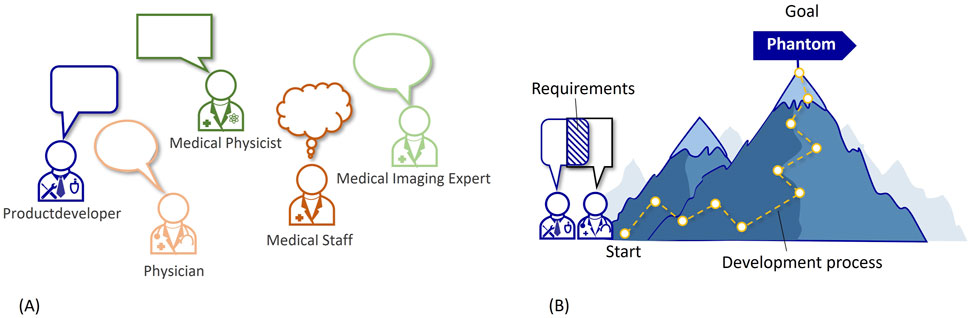
Figure 1. (A) Different stakeholders in the phantom requirements analysis. (B) Illustration of the development process.
Medical phantoms have a wide range of applications, including medical imaging and therapies. Each application has unique requirements, so that creating a generic requirements list that covers all scenarios can be difficult. Addressing these challenges requires a systematic approach for the requirement analysis, involving close collaboration between stakeholders, thorough understanding of application-specific needs, and continuous feedback and iteration throughout the development process. This is why requirement determination is so important at the beginning of a phantom development process. This is visualized in Figure 1B with the development process as a path leading up a mountain to the goal (=phantom). The start of this process being the defined requirements.
When characterizing phantoms, it is important to consider that phantoms, as medical models, can fit into Stachowiak’s general model theory [18], which characterizes models by at least three key properties: (i) mapping, (ii) reduction, and (iii) pragmatism. According to this theory, a model always serves as a representation or image of some existing or conceptualized original, which is, in the case of phantoms, often a human patient, but could also be an animal. Nevertheless, a model is not an exhaustive representation of its original, but rather mimics only those attributes that are considered to be relevant in a specific project [18], see Figure 2. For example, this results in a phantom serving as a practical representation of a human torso in the medical imaging of lungs. The original has preteritive attributes, which are omitted and not covered by the model and the model has abundant attributes that do non’t correspond the original (c.f. Figure 2). These reduction and mapping criteria need to be collected through the requirements assessment and put into the requirements list. For medical simulation models, this degree of representation is also often referred to as fidelity [19]. In this work, the term mapping is chosen for the level of the reality representation based on the basic model concept of Stachowiak [18] (see Figure 2).
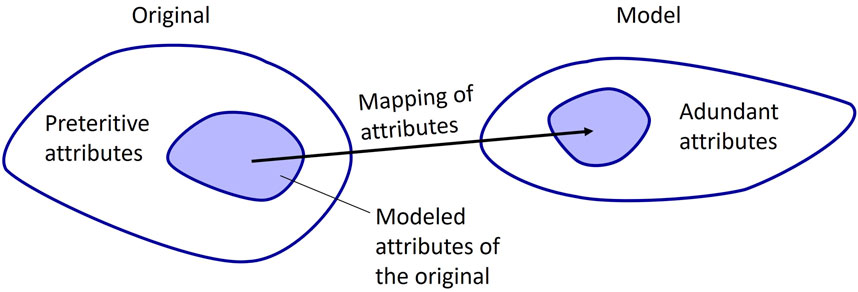
Figure 2. Mapping from original to model, based on Stachowiak [18].
We present here, for the first time, the importance of supporting the requirement analysis in medical phantom development. Moreover, we present a process to gather and structure phantom requirements. This process can be used as a guideline to collect requirements from different stakeholders and structure them according to phantom needs. The process includes a novel survey tool for gathering and classifying requirements, which are specific for phantom development. To show and validate the application of the presented approach and tools, we present in the results the development of a multimodal deformable pelvic phantom and include an extract of the phantom application.
2 Materials and methods
The overall process developed in this study to gather and structure phantom requirements in the planning phase is displayed in Figure 3. It involves four steps: 1. Identify stakeholders, 2. Gather requirements via survey, 3. Create requirement lists, 4. Review and prioritize requirements lists. During the collection of phantom requirements (step 2), it is useful to integrate knowledge of typical phantom characteristics. These characteristics are included in the survey, cf. Figure 3, steps 2a to 2d.
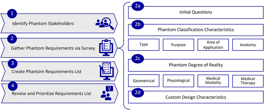
Figure 3. Process for gathering and structuring phantom requirements, with steps 1 to 4 and sub steps 2a to 2d.
2.1 Identify phantom stakeholders (step 1)
The first step should aim at identifying all stakeholders involved in the phantom development and use. These typically include medical staff, physicians, medical physicists, medical imaging experts, product developers, and phantom end-users. The experts may also overlap in their roles (or have multiple roles) and are highly dependent on the phantom application area. For example, a phantom, which will be used in mammography, will involve radiologists for aspects related to image quality and main characteristics, medical staff for handling during positioning and/or imaging, medical physicists for analyzing image resolution, reproducibility, or geometry, product developers for the development process.
2.2 Gather phantom requirements via survey (step 2)
Since medical stakeholders may lack familiarity with formulating and identifying requirements, and developers may not be familiar in the specifics of the desired phantom, it becomes crucial for all groups to closely collaborate to gather the requirements on the phantom in an effective way. This important step could be taken by organizing a workshop or, as envisaged here, with an online survey. The advantage of an online survey with respect to a workshop are e.g., consistency, remote collaboration, data integrity, flexibility, time efficiency, scalability.
This approach gives all stakeholders the opportunity to name requirements, usually according to a guideline, and sort them into different categories. This can already be performed during the gathering process and will result in a list of requirements that is as structured and holistic as possible. In the next sections, the methodology will be illustrated in more details.
2.2.1 Survey design
Since phantoms encompass different applications and are each tailored to specific needs within the fields of medical imaging and/or image-guided therapy, it is important to include in the survey as many phantom characteristic requirements as possible. To gather the questions for the survey and include a variety of different phantom types, we analyzed English author keywords in the literature regarding medical imaging phantoms from the last 30 years (1994–2024), with the help of the Scopus database (Elsevier B.V., Netherlands). Filtering for “phantom” in the title and “imaging” in title, abstract or keyword, resulted in 9,387 publications with 14,361 author keywords. An excerpt of the top 25 author keywords can be seen in Table 1. These keywords show, on the one hand, the different imaging applications of phantoms, like computed tomography (CT), magnetic resonance imaging (MRI), ultrasound (US), mammography, positron-emission tomography (PET), single-photon emission computed tomography (SPECT). On the other hand, we found frequent mention of use in therapy, such as radiotherapy, as well as in quality assurance, calibration, and validation. Furthermore, phantom manufacturing using 3D printing appeared to be a common topic.
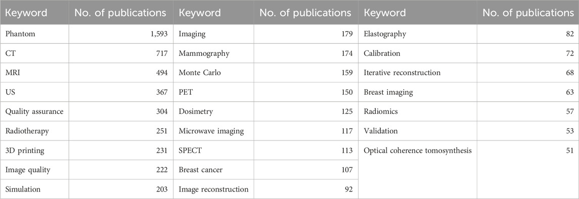
Table 1. Top 25 keywords occurrences in phantom literature (from Scopus database 1994–2024).
Based on this literature analysis, we derived a classification for phantoms requirements and used it as a guideline in this work for gathering phantom requirements. Together with the keyword analysis, we also refined and adapted our criteria to define phantom characteristics based on our previous work, which aimed to classify phantoms for medical imaging [3]. Figure 3 shows the resulting phantom requirements (Steps 2b to d), which will be explained in the following.
To create a support tool for structured gathering of phantom requirements, we designed, in a second step, a survey in Microsoft Forms (Microsoft Cooperation, United States), as illustrated in Figure 4, with a total of 110 implemented questions. The survey was created in German and English and focuses on the specific requirements that are common in medical phantoms. It is designed to offer a choice of answers and provides links to follow-up questions. For example, if the phantom is to be used in radiation dosimetry, we provide a list of different dosimeters that can be fitted inside or on the phantom.
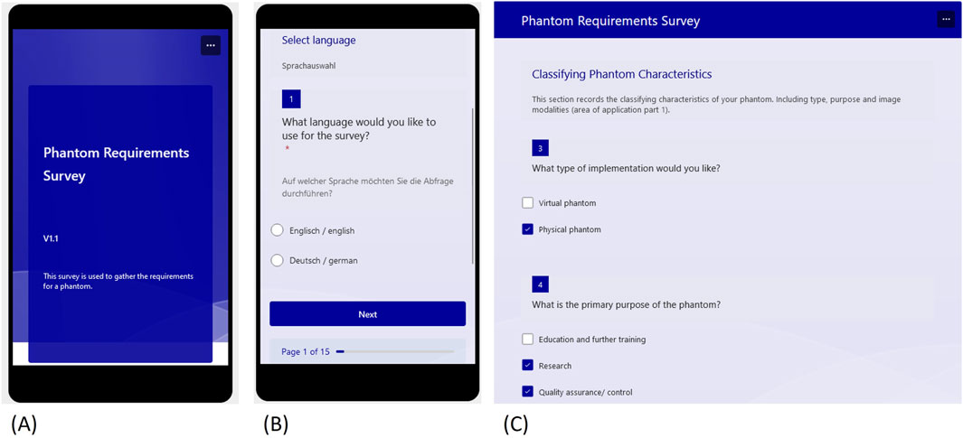
Figure 4. Excerpts from the requirements survey designed in Microsoft Forms (A) Start view (B) Language selection (C) Start of the classification questions.
2.2.2 Survey steps
2.2.2.1 Defining phantom type and purpose
The questionnaire begins with the language choice, followed by a text question asking to briefly state the kind of phantom which is to be developed. This answer will later be used as the scope and should be a short but precise description, like “deformable pelvic phantom for CT, MRI and US imaging”, which will be the example that is described in chapter three. Following this initial section, the questionnaire moves on to the collection of phantom classification characteristics. These consist of phantom type, purpose, area of application, and anatomy. The phantom type describes the choice of a virtual or a physical phantom (or both). The purpose can be (i) quality-assurance/-control and calibration (which also includes dosimetry as a sub-category), (ii) research, or (iii) education and training. The purpose later defines the realization depth of the imaging properties, which should meet the needed accuracy requirements, while still fulfilling an adequate effort-to-benefit ratio.
2.2.2.2 Specifying the area of applications and anatomy
As stated above, the two primary domains of applications for phantoms are medical imaging and image-guided therapies. Within medical imaging, modalities can be categorized as clinical or preclinical, such as micro-CT or micro-PET. The survey initially focuses on defining the imaging modalities, beginning with whether one or more modalities (multimodality) are desired. Subsequently, the dominant imaging modalities–X-ray/Radiography, MRI, US, and nuclear medicine/emission–are presented as choices. If one is selected, follow-up questions regarding specifications will appear. For instance, within X-ray/Radiography, options like CT, mammography, angiography, etc., are provided. This querying process is repeated for multimodality until all desired imaging modalities are addressed. Additionally, there is an open-entry field for any modality that is not included in the initial list.
Following the imaging modality selection, respondents can choose the option of image-guided therapeutic applications. If this is the case, follow-up questions related to the chosen therapy appear. The surveyed therapies encompass, among others, radiation therapy applications, surgical procedures (such as biopsy), and thermal therapy. Also in this case, the user can answer specific follow-up questions, which are tailored to the chosen therapy type. As an example, if choosing radiotherapy, it is possible to distinguish between external-beam radiotherapy or brachytherapy.
After the application section, the final characteristic category is the anatomy. Phantom anatomy is divided into two main components: topographical anatomy and organs/tissues to be included. Topographical anatomy includes body regions, e.g, head, thorax, abdomen, and upper or lower extremities. Within a region, users can specific organs or tissues to be represented, such as heart, brain, liver, lungs, bone, or bone marrow.
2.2.2.3 Defining the degree of reality
Once the classifying characteristics have been collected, the questionnaire moves on to record the degree of phantom reality or fidelity (see Figure 3). This is broken down into the following four aspects: (i) geometrical, (ii) physiological, (iii) medical modality and (iv) medical therapy mapping. The last two are both part of the clinical application, but are intentionally subdivided to obtain a more detailed description of the desired phantom.
The type of geometric mapping of the phantoms can be specified together with the degree of geometric mapping, which varies along a gradual scale. Figure 5A provides a visual aid to illustrate this variation. The questionnaire offers three distinct categories for the sake of simplification. The first category, “Geometrical or Abstract,” includes simple geometric shapes, like cubes or cylinders, to represent the phantom. Following this, the “Object Based” category refers to more anthropomorphic (human-like) or zoomorphic (animal-like) representations. Lastly, the “Object Specific” category entails the precise replication of an object, such as a patient. It is important to note that the scale is not intended to rate the phantom, but rather to record the desired degree of mapping.
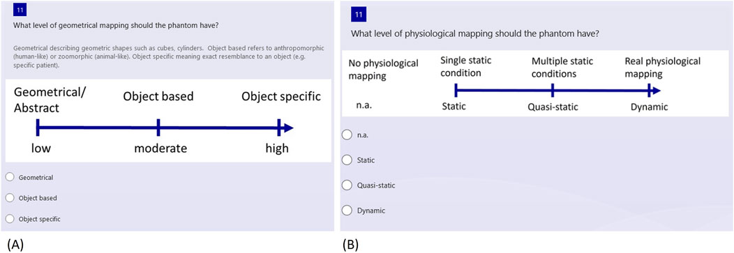
Figure 5. Selection of questions regarding the phantom reality degree (A) Geometrical mapping (B) Physiological mapping.
Next, the level of physiological mapping is addressed, as depicted in Figure 5B. This aspect relates to physiological features, such as a representation of blood flow or organ movement. If no physiological mapping is necessary, “n.a.” for “not applicable” can be selected. Alternatively, the options range from static to quasi-static and dynamic, depending on the complexity of the conditions that need to be represented.
2.2.2.4 Level of resemblance
Depending on the use, it is of help to gather information on the level of resemblance for the imaging modalities and medical therapies, ranging from partial resemblance to realistic resemblance, which, in turn, can be defined as low, moderate, or high. A high modality resemblance is related to a specific range of values of a physical quantity. As an example, the user could require the CT numbers (HU-values) to be satisfied within a deviation of ± 10%. A low resemblance could be more qualitative, like a tissue being darker or lighter in imaging than another one, without having the same physical properties as the mimicked object.
2.2.2.5 Customization
The final section of the survey includes custom design characteristics, again providing single and multiple-choice questions, as well as follow-up questions. These questions are about individual requirements and may relate to dimensions, weight, durability, production consistency, transportability, and reproducibility of the required phantom. In addition, a free text question allows respondents to specify any number of other requirements, with examples provided for guidance, such as “the phantom should be operable by untrained personnel”.
While the questionnaire serves as a valuable tool for structuring and obtaining a comprehensive overview of common phantom requirements, it is advisable to subsequently verify the completeness of the collected requirements and tailor them to individual needs. Therefore, the questionnaire is intended as a supporting tool and should not be regarded as universal.
2.3 Create requirements list (step 3)
After the phantom requirements are collected with the support of the Forms questionnaire, the results can be used to generate a requirements list. To simplify this step, we programmed an interface in Microsoft Excel (Microsoft Cooperation, United States, Version 2108) using Visual Basic for Applications (VBA) as the programming language, which helps to integrate the survey results into a requirements table in an automated way. The graphical user interface (GUI) consists of four buttons (Figure 6A), one to load the survey results, one to create the list, one to edit the list, and, finally, one to reset the list. Excel toolbars are hidden but can reappear when clicking “show toolbar” in the menu. This prevents the user from directly accessing the developer pages.
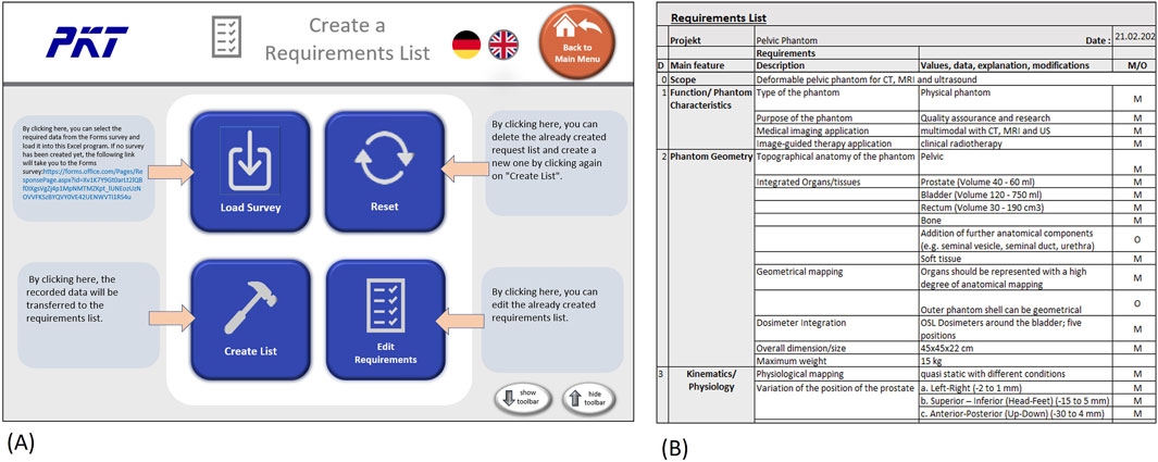
Figure 6. Creating and editing requirements list in Excel (A) GUI with buttons to generate and edit list (B) Example of a dervied requirements list (exerpt).
The creation or editing of the list will bring the user to the requirement list page, as can be seen in Figure 6B. On this page, the user can further edit the list or print it out. The “Menu” button leads back to the starting page, where another survey could be loaded or the list reset.
The requirements list includes an introduction/scope, which reports the description of the phantom from the first initial question in the survey (cf. Figure 6B). The introduction is followed by the functional requirements, which include the classification characteristics of the phantom, except for the anatomy. Since this section is still very generic, the specifications for modality mapping and the desired values follow in separate categories. Next, the geometrical requirements are listed, these include the anatomy of the phantom as well as dimensions and weight restrictions. Preliminary organ sizes or volume should be added in this category as well.
Once the geometrical requirements are specified, the following category focuses on the physiological mapping of the phantom. This should state, if possible, the conditions the phantom is supposed to represent, with precise numerical values (or rough estimates in the initial stage). The transfer of information from the survey shows that many details need to be added in this stage, since the gathering process allows one to collect generic and categorical information only.
The medical application requirements, consisting of imaging and therapy requirements and their mapping scale, are listed in their own category as well. The needed type of imaging and the level of mapping scale will be now transferred into the requirements list. Transportation, maintenance and manufacturing have their own category. The available production costs and the completion date should be included in the manufacturing category.
2.4 Review and prioritize requirements (step 4)
After creating the requirements list, all involved stakeholders proceed to the review. At this stage, it is also important to differentiate the listed requirements into mandatory and optional requirements. If needed, optional requirements can also be prioritized at different levels (1–3).
Since measurability of the requirement is a prerequisite for tracking and assessing its implementation during phantom development, each requirement should be stated in quantitative terms. If applicable, qualitative requirements should be converted into quantitatively formulated requirements for further use in the development process, by adding tolerances and specific values as well. For example, in the case of tissue contrasts in imaging, an evaluation of the grey scale between 10 (“very good”) and 0 (“very bad”) would help to better specify this property, even if the matching physical quantity (e.g., relaxation times in MRI) is not mandatory.
2.5 Further phantom development (concept, design and validation)
After finalizing the previously addressed planning phase and its output (the requirements list), the development processes typically continue with the three phases of concept, design, and validation. The concept phase encompasses the choice of the phantom solution and corresponding surrogate materials. A specialty for phantom development is the focus on the material testing, which has a major focus. The design of individual modules and the overall design are then created in the design phase. A useful tool in this phase could also be a Module Interface Graph (MIG) [20], which shows the arrangement of the components of a product as well as flows and interfaces between them (for an example, see Figure 7A below).
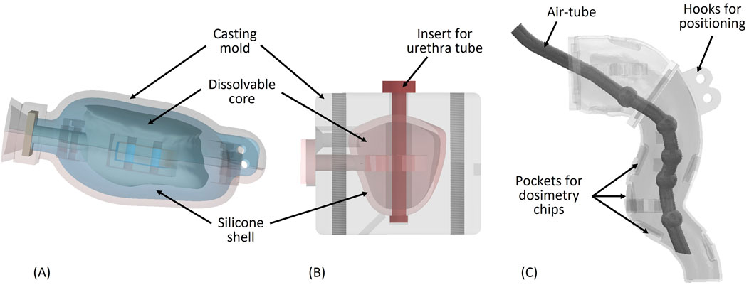
Figure 7. (A) Bladder mold with dissolvable core (B) Prostate mold with dissolvable core and urethra tube (C) Rectum wall with air tube inside.
Finally, the phantom is manufactured and validated during the validation phase. This final procedure involves analyzing the application of the phantom together with the stakeholders. Verification, in contrast to validation, takes typically place during the development process and involves comparing design outputs to design inputs, focusing more on quantitative methods. During validation, the user needs and intended uses are checked. While this differentiation between verification and validation is common in engineering design [16, 21], in the literature regarding phantoms, it is often not separated and not even specified. An appropriate approach would be to use the requirements list as a checklist for verification. Material properties could be compared against the desired values, as it is crucial that the surrogate material of a phantom meets various criteria for imaging and therapy. These criteria may include suitable attenuation coefficients or magnetic resonance relaxation times, depending on the intended application of the phantom. Comparisons should be conducted in house using patient or other phantom data from the same medical device and setting used with the designed phantom. Additionally, comparisons should be made with patient data that are documented in literature or with other phantoms, either from publications or available commercially. In this case, it is important to consider the settings of the image acquisition as well. Satisfaction of the requirements could be rated using a weighted evaluation together with a satisfaction scale of 0–four or a tendency (+, o, -) [21]. An additional weighting factor would help to indicate the relative importance of the evaluated criteria. For phantoms, verification could be done during the development process, as well as simultaneously to the final validation, which should be conducted with the stakeholders after development and focus more on qualitative questions. This could be done, for example, with a questionnaire. Since this article focuses preliminary on the requirements support, the phantom concept, design and validation phases are not further addressed in detail.
3 Results
To validate the phantom requirements approach, we applied the presented methodology to develop a multimodal deformable pelvic phantom. This phantom should enable quality assurance of radiotherapy procedures for prostate cancer and should mimic deformations and changes in position of the prostate resulting from variation of organ fillings, in particular of bladder and rectum. This physical phantom allows one to investigate, in a multimodal end-to-end test, the influence of anatomy changes on the planned radiation dose distribution, both in the prostate and in the surrounding sensitive organs (in particular rectum and bladder).
To develop the phantom, we used the approach described in chapter 2. Firstly, we identified the stakeholders, which, in this case, are professionals of the departments of radiology and radiotherapy. In particular, they comprise imaging experts for MRI, CT, US, as well as radiation oncologists, medical physicists, and radiation therapists. Secondly, we gathered the requirements on the phantom using the designed survey. Table 2 shows an extract of the collected requirements, listing the phantom characteristics according to each category. The pelvic phantom is a physical phantom, designed for quality assurance and research. Medical imaging applications are CT, MRI, and US, while external-beam radiotherapy is the image-guided therapy application we aimed for. The phantom covers the topographical anatomy of the pelvic region and should contain various tissues such as bone, bladder, rectum, prostate, and surrounding soft tissue.
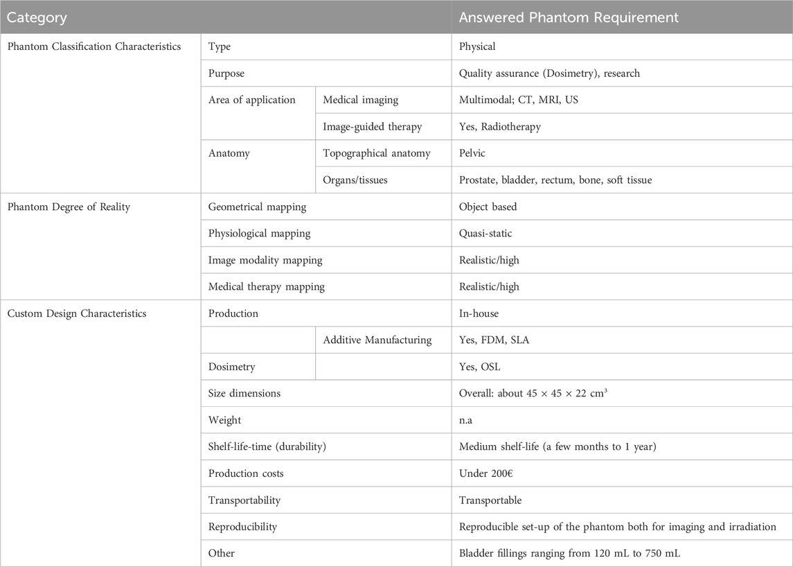
Table 2. Excerpt of the pelvic phantom requirements collected in the Forms survey.
The geometrical mapping of the phantom was expected to be moderate, meaning that the anatomical structures for some inner organs should satisfy a high degree of anatomical details, but the outer shell can also have a simplified geometry. Physiological resemblance is desired as a quasi-static. In fact, the organ fillings of the bladder and rectum should represent multiple static conditions, ranging from 120 mL to 750 mL for the bladder, which is later specified in the custom requirements questions. Imaging and therapy mapping levels are supposed to be realistic, since the phantom should be used for quality testing and experiments. This means that the physical properties of the surrogate materials need to match the original tissues. Thus, we conducted a thorough research to determine these parameters, for each tissue in each imaging modality, together with the definition of an accepted deviation range from these parameters.
For complying with the above-mentioned custom characteristics, a viable option is the in-house-production, which could be combined with the use of additive manufacturing, if applicable. The available AM methods, which could be used for manufacturing, are therefore listed under the category “custom design characteristics” and marked for later consideration during the assessment of solution concepts. Thanks to the survey, we gather also information on several important requirements, such as dimensions, shelf-life-time, production costs, transportability, and reproducibility, see Table 2.
We derived the list of requirements from the survey information, as described above and handed it over to the stakeholder team for review and for sorting all requirements into optional and mandatory. During this process, we added numerical values of physical parameters that are relevant for the desired imaging modalities. For example, to gather information about the range of realistic CT numbers and the morphology/movement of inner organs in the pelvic region, we analyzed patient images that were recorded in the clinic with the same CT-scanner with which the phantom will be used. In addition, we carried out a literature review concerning tissue properties in patients and those achieved by existing phantoms, in order to establish an acceptable value range. This research was done for each tissue included in the phantom and each modality.
In the next step, we designed and manufactured the phantom (Figure 7). Since the realization of different inner organ positions and deformations is a challenging task, the use of a MIG was very helpful to visually structure the desired standard and variant components (Figure 8A). The final selection of materials in the solution concept was preceded by verifications of their suitability as tissue surrogates in medical imaging. These verifications consisted in measuring the Hounsfield units (CT), the longitudinal and transverse relaxation times (MRI), and the sound propagation velocities (US). Finally, we manufactured all components and assembled the phantom.
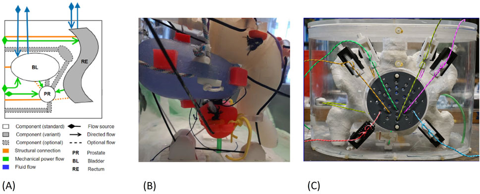
Figure 8. (A) Exerpt of the MIG for the pelvic phantom (B) Organ positions inside the phantom: bladder in blue, prostate in red, rectum in white (C) Assembled pelvic phantom.
For the internal organs, we used additive manufacturing (AM) to achieve a high degree of anatomical accuracy. We created STL mesh models of pelvic bones, femoral heads, and bladder based on CT images of prostate cancer patients using 3D Slicer [22]. The models were segmented in 3D Slicer, edited in Autodesk Inventor (Autodesk, Inc., San Rafael, CA, United States) and sliced in the appropriate 3D printing software. This follows the typical design and 3D printing preparation process for medical models [23].
For manufacturing the bony structures of the pelvis and femoral heads, we 3D-printed hollow bone shells out of ABS using the Fused Deposition Modeling (FDM) process, with a HP Designjet Color (HP Inc., Palo Alto, United States). The bone had to be divided into five segments due to the limited construction space of the printer. The 3D printer also prints a support material, which is afterwards dissolved in a chemical water bath. Each bone part was filled with a mixture of vaseline and dipotassium hydrogen phosphate (K2HPO4) to represent the spongy bone consisting of red and yellow bone marrow. To simulate cortical bone, which contains a lot of calcium, we applied a coating of plaster (plaster bandages) and, finally, a clear wax coating for protection.
For crafting the urinary bladder, we used indirect AM, printing a mold with a stereolithography (SLA) printer (Form three by Formlabs Inc., Somerville, MA, United States), together with an FDM-printed dissolvable core out of polyvinyl alcohol (PVA) [24] (Figure 7A). Bladder deformation with different wall thickness was simulated in Autodesk Inventor to realize an appropriate bladder shape and deformation pattern comparable to patient deformations observed in inhouse clinical data as well as literature results [25]. Finally, we filled the mold with two component RTV silicon (RTV2 Shore hardness 33 by Silikonfabrik.de, Germany) and removed the PVA core using water to obtain a deformable silicon bladder wall, with a wall thickness varying between 1.5 and 3 mm. The bladder volume of the final model can be varied in the range 100–750 mL using water as filling.
The prostate design was based on the sector map of PI-RADS V2.1 [26], which was generated into a 3D model in Autodesk Inventor. The prostate size was scaled to 52.5 mL (dimensions: 54 × 43 × 42 H × L × W mm3). Similar to the bladder, the prostate was also casted using a printed mold and a dissolvable core (Figure 7B). The prostate shell is represented by silicon, while the filling consists of a mixture of agarose, EDTA, Cu2+, glass beads, lipid particles, proteins, and water.
As foundation for the rectum shape, we considered general rectum and colon 3D models, taken from BodyParts3D/Anatomography1, a public library of 3D organ models. We then adapted this form to better fit the prostate and bladder assembly and correspond to the correct anatomical measurements. The phantom rectum wall was set to 2 mm to mimic the average anatomical values. Inside the rectal shell, interchangeable air-tubes may be placed to simulate gas bubbles of varying number and volume, with dimensions between 6 and 11 mm (Figure 7C). We manufactured the rectum wall and the variant air tubes directly, using an SLA printed flexible resin (Flexible 80 A by Formlabs Inc). After placing the air-tube inside of the rectum shell, the shell was filled with Vaseline as surrogate.
Bladder, prostate and rectum walls have small positioning hooks where a thread connects the organs to the positioning system (see Figure 7, Figure 8B), which is located outside of the housing (see Figure 8C). The positions can be adjusted from the outside using an AM printed lead screw. The prostate is also linked to the bladder using a urethra-like connection, a flexible tube with a 6 mm diameter. We also attached small 3D-printed pockets to the organ walls for securing optically stimulated luminescence (OSL) dosimeters inside the pelvic phantom. Pictures of the manufactured and assembled phantom can be seen in Figures 8B, C.
To verify that all the defined requirements were achieved, we performed a couple of different verification tests, as shown in Figure 9. To systematical verify the satisfaction of the phantom requirements, we took the requirements list as a checklist. Each requirement was given a weighted factor, a numbers between 0 and 1, whereby the sum of all criteria equals 1. Then the fulfillment of each criterion was assessed and assigned a satisfaction scale ranging from 0 to 4, where 0 indicates no compliance and four indicates full compliance. The focus of the validation was primarily on comparing the mapping features, consisting of the degree of medical imaging, therapy, geometrical, and physiological mapping.
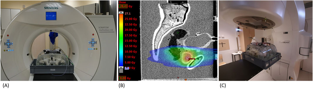
Figure 9. Application of the pelvic phantom (A) Phantom in CT-scanner (B) CT-scan and radiotherapy plan (C) Phantom in linear accelerator.
A main point of interest was the image modality representations of the phantom in CT, MRI, and US. This was done, on the one hand, on the basis of measurements of CT numbers in Hounsfield Units (HU) (cf. Table 3), MRI relaxation times T1 and T2 (cf. Table 4), and the sound velocities (US). On the other hand, the evaluation took the visual appearance (tissue contrast) in the medical images into consideration. The used CT scanner, with setup depicted in Figure 9A, was a Siemens Somatom Definition AS with a voltage of 120 kVp (Siemens Healthcare GmbH, Erlangen, Germany), while the MRI scanner was a 1.5T Philips Achieva (Philips Medical Systems DMC GmbH, Hamburg, Germany). For US imaging, we used a Sonoline Omnia (Siemens Healthcare GmbH, Erlangen, Germany), as well as a test setup to measure sound velocities with a frequency generator and an oscilloscope.
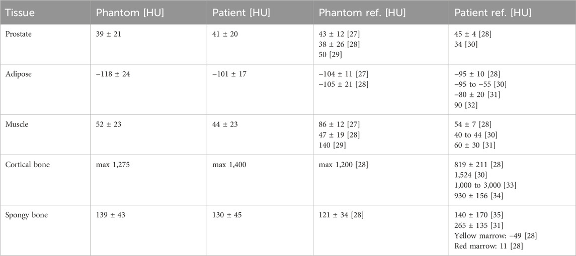
Table 3. CT phantom results. Patient HU values acquired at same device and setting as phantom. Phantom and patient references from literature [27–36] listed for comparison.
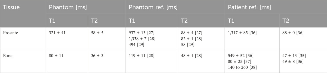
Table 4. MRI phantom results with T1-and T2-relaxation times for 1.5 T. Phantom and patient references from literature [27–29, 35–38] listed for comparison.
The results of the measured CT numbers are listed in Table 3, and MRI relaxation times (T1 and T2) in Table 4, together with corresponding literature data. We evaluated the CT numbers using a region of interest (ROI) in ImageJ [39] and determined mean values and standard deviation across multiple slices. Variable flip angle (VFA) imaging with varying flip angles were used for the determination of T1. T2 was determined from a turbo spin echo (TSE) image with a repetition time (TR) selected five times as large as the expected T2. Since we could not acquire relaxation times and sound velocities in patient tissues during clinical diagnostic imaging, we referred to literature data for comparison. US results with measured sound velocities are given in Table 5.
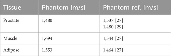
Table 5. US phantom sound velocities with phantom references from literature [27, 29] listed for comparison.
For the geometrical mapping, the acquired CT and MRI medical images were aligned with patient images in the treatment planning software Eclipse™ (Varian Medical Systems Inc., Paulo Alto, United States) and evaluated by medical personnel to verify the anatomical appearance of the phantom. Using a questionnaire, the appearance was also rated as very realistic.
To test the dosimetry capabilities of the phantom, we simulated a radiotherapy treatment with a typical patient treatment plan (see Figure 9B), and irradiated it at a linear accelerator (TrueBeam by Varian Medical Systems Inc., Paulo Alto, United States). The setup of the pelvic phantom for irradiation can be seen in Figure 9C. The dosimetry tests, performed with OSL dosimeters as well as radiochromic films (Gafchromic™ EBT3, Ashland Advanced Materials, Bridgewater, United States) showed that the built-in structures allowed for reproducible dose measurements in the most critical locations. The maximum difference between the values measured with radiochromic films and the planned dose was 16.6%. Additionally, we could insert a dosimetry gel into the designed prostate shell for future 3D dosimetry studies. The phantom can be used to study the effect of changes on the dose to the prostate and the surrounding organs, due to different positions of the prostate induced by different bladder and rectal filling levels.
For the physiological mapping, extensive kinematics tests were conducted to verify the precision and reproducibility of the position shifts and linkage. We found that the prostate phantom is strongly linked to the bladder, meaning that a bladder position shift induces a proportional response of the prostate. The volume-induced deformation of the bladder influenced the prostate position, further verifying the connection. The flexible tube structure, moreover, allows for independent adjustment of the prostate in the lateral direction. The prostate is laterally restricted by the bone structure to a total motion of about 7 mm and may be, therefore, shifted up to 3.5 mm both in the left and right direction. The prostate is also linked to the rectum, but to a lesser extent. Due to the arrangement of the positioning system, some movements of the bladder and rectum in the phantom are a combination of multiple directions. This means that one adjustment may simultaneously change two coordinates of an element. All in all, the components can be moved reproducibly and precisely within a range of 7 mm–8 mm around the starting position assembly.
4 Discussion
This paper addresses, for the first time, to our knowledge, the crucial role and importance of a structured and holistic requirement analysis in medical phantom development. We introduce a novel survey tool, which is tailored for gathering and categorizing requirements in a specific way for phantom development. With this tool, we have provided a structured approach to ensure that the diverse needs of stakeholders are effectively captured and addressed. The survey was structured to gather phantom characteristics ranging from classification to the degree of reality mapping and custom design characteristics.
Nevertheless, the requirements survey should only be seen as a guideline and not as a holistic support. Workshops and brainstorming with stakeholders should be included in the development process as well. Moreover, the requirements list is not static and should be kept up to date during the whole development process. It is also important to note that for more complex phantoms a structured approach will be more helpful than for a simple geometrical phantom. The advantages of having used the requirement analysis during the development of the phantom consists in clearly defining the objectives and specifications of the phantom. This ensures that all stakeholders have a shared understanding of the phantom’s purpose, characteristics, and performance criteria, allowing for an alignment with stakeholder needs. This also enables developers to continuously monitor and evaluate the phantom throughout the development lifecycle, ensuring that it meets these specifications.
The developed deformable multimodal pelvic phantom gives an illustrative example of how the approach can be used and that structuring the requirements while gathering them from different stakeholders offers an efficient procedure to obtain a final product, which can be reviewed and updated by any stakeholder at any stage. The pelvic phantom was developed to improve the quality assurance of the entire radiotherapy procedure for prostate cancer. The multimodal pelvic phantoms applications are illustrated in Figure 8, which demonstrates end-to-end testing in prostate cancer radiotherapy. This includes target volume definition, treatment planning, image guidance for localisation of the prostate, and dose determination. The phantom can be used to mimic and study the effect of daily changes in prostate position due to bladder and rectal filling levels in the patient, and to determine the extent to which deformable registration software can be used for quality assurance.
The imaging parameters (see Tables 3–5) show overall good agreement compared to patient data acquired on the same devices, as well as literature data of phantoms and patients. In particular, the HU values for the prostate and bone surrogates closely matched the literature values, while the other tissue surrogates also scored high on the satisfaction scale. The T1 relaxation time for the prostate surrogate was lower than literature and could be improved. However, the prostate is very clearly recognizable on the T1-weighted images, which is ideal for treatment planning. This result is given more significance, through the weighted factor, than a suitable T1 time. The sound velocities of the tissues are comparable to values in other phantom literature and show satisfactory agreement. As mentioned earlier, we also focused, for all three imaging modalities, on the correct contrast, such as the relative brightness or darkness of a tissue compared both to others and to the surroundings. For this rating, every relevant tissue could score at least three out of four points.
For the physiological mapping the pelvic phantom demonstrated that there is little deviation in the position of the individual components, meaning that the phantom properly represents the anatomy. The movement range of the organs is sufficient for simulation of prostate intrafractional motion during radiotherapy [40] as well. Furthermore, dosimetry experiments showed good agreement between planned and delivered dose. Other requirements of the phantom were also checked for satisfaction and showed overall good results, though some requirements were only partially fulfilled. For example, the positioning system is occasionally noticeable in imaging. While this did not negatively impact the test outcomes, it is not rated as optimal. Another point is the assembly: although assembling the individual components is straightforward, positioning them within the pelvic phantom is challenging due to the bone structure. The bone structure obstructs the view, and arranging the thread around it is not simple to execute. Nevertheless, the experiments demonstrated that the pelvic phantom can be operated and transported by one person. Through a final verification, we could conclude that all the requirements were sufficiently fulfilled.
Looking ahead, future research in phantom development and validation should explore innovative methods and techniques to further enhance the accuracy, realism, and applicability of phantoms in medical imaging and therapy. One avenue for advancement lies in the automated integration of imaging modalities to optimize phantom design and validation processes. Furthermore, the use of novel materials and fabrication techniques, including 3D printing, holds promise for creating phantoms with customizable properties and functionalities.
There is a growing need for standardized protocols and benchmarks for phantom verification and validation across different imaging and therapy modalities. Establishing rigorous validation criteria and performance metrics will facilitate the objective assessment of phantom performance and ensure consistency and comparability across studies. Collaborative efforts among researchers, clinicians, and engineers will be essential in developing and implementing these standards effectively.
In summary, future research in phantom development and validation should focus on harnessing emerging technologies, establishing standardized protocols, exploring novel materials and fabrication techniques to enhance the utility and effectiveness of phantoms in medical imaging and therapy.
Data availability statement
The original contributions presented in the study are included in the article/supplementary material, further inquiries can be directed to the corresponding author.
Author contributions
MW: Conceptualization, Investigation, Methodology, Writing–original draft, Writing–review and editing, Visualization, Data curation. JS: Writing–review and editing. ES: Writing–review and editing. DK: Project administration, Resources, Supervision, Writing–review and editing. EG: Methodology, Resources, Supervision, Validation, Writing–original draft, Writing–review and editing.
Funding
The author(s) declare that financial support was received for the research, authorship, and/or publication of this article. Publishing fees supported by Funding Programme Open Access Publishing of Hamburg University of Technology (TUHH).
Conflict of interest
The authors declare that the research was conducted in the absence of any commercial or financial relationships that could be construed as a potential conflict of interest.
Publisher’s note
All claims expressed in this article are solely those of the authors and do not necessarily represent those of their affiliated organizations, or those of the publisher, the editors and the reviewers. Any product that may be evaluated in this article, or claim that may be made by its manufacturer, is not guaranteed or endorsed by the publisher.
Footnotes
1http://lifesciencedb.jp/ag/bp3d/
References
1. Filippou V, Tsoumpas C. Recent advances on the development of phantoms using 3D printing for imaging with CT, MRI, PET, SPECT, and ultrasound. Med Phys (2018) 45:e740–e760. doi:10.1002/mp.13058
2. DeWerd LA, Kissick M. The phantoms of medical and health physics. New York, NY: Springer New York (2014). 290.
3. Wegner M, Gargioni E, Krause D. Classification of phantoms for medical imaging. Proced CIRP (2023) 119:1140–5. doi:10.1016/j.procir.2023.03.154
4. Valladares A, Beyer T, Rausch I. Physical imaging phantoms for simulation of tumor heterogeneity in PET, CT, and MRI: an overview of existing designs. Med Phys (2020) 47:2023–37. doi:10.1002/mp.14045
5. Tino R, Yeo A, Leary M, Brandt M, Kron T. A systematic review on 3D-printed imaging and dosimetry phantoms in radiation therapy. Technol Cancer Res Treat (2019) 18:153303381987020. doi:10.1177/1533033819870208
6. Garcia J, Yang Z, Mongrain R, Leask RL, Lachapelle K. 3D printing materials and their use in medical education: a review of current technology and trends for the future. BMJ Simul Technol Enhanc Learn (2018) 4:27–40. doi:10.1136/bmjstel-2017-000234
7. Wake N, Ianniello C, Brown R, Collins CM. 3D printed imaging phantoms. In: 3D printing for the radiologist. Elsevier (2022). 175–89.
8. Pogue BW, Patterson MS. Review of tissue simulating phantoms for optical spectroscopy, imaging and dosimetry. J Biomed Opt (2006) 11:041102. doi:10.1117/1.2335429
9. Hacker L, Wabnitz H, Pifferi A, Pfefer TJ, Pogue BW, Bohndiek SE. Criteria for the design of tissue-mimicking phantoms for the standardization of biophotonic instrumentation. Nat Biomed Eng (2022) 6:541–58. doi:10.1038/s41551-022-00890-6
10. Ehrlenspiel K, Meerkamm H. Integrierte produktentwicklung: denkabläufe, methodeneinsatz, zusammenarbeit. München: Hanser (2013). 826.
11. Verein Deutscher Ingenieure. VDI 2221: design of technical products and systems Model of product design. VDI-Richtlinien (2019).
12. Verein Deutscher Ingenieure. VDI 2222: Konstruktionsmethodik - Methodisches Entwickeln von Lösungsprinzipien. VDI-Richtlinien (1997).
13. Feldhusen J, Grote K-H. Pahl/beitz konstruktionslehre. Berlin, Heidelberg: Springer Berlin Heidelberg (2013).
15. Koller R. Konstruktionslehre für den Maschinenbau: Grundlagen zur Neu-und Weiterentwicklung technischer Produkte mit Beispielen. Berlin, Heidelberg: Springer (1998). 692.
16. Wallace K, Blessing LT. Engineering design: a systematic approach. London: Springer (2007). 617.
17. Pohl K, Rupp C. Basiswissen requirements engineering: Aus-und Weiterbildung zum. In: “Certified Professional for Requirements Engineering” foundation level nach IREB-Standard. Heidelberg: dpunkt.verlag (2015). 171.
19. Tun JK, Alinier G, Tang J, Kneebone RL. Redefining simulation fidelity for Healthcare education. Simulation and Gaming (2015) 46:159–74. doi:10.1177/1046878115576103
20. Krause D, Gebhardt N. Methodical development of modular product families: developing high product diversity in a manageable way. Berlin, Heidelberg: Springer Berlin Heidelberg (2023). 261.
21. Albers A, Behrendt M, Klingler S, Matros K. Verifikation und Validierung im Produktentstehungsprozess. In: Handbuch produktentwicklung. Carl Hanser Verlag GmbH and Co. KG (2016). 541–69. doi:10.3139/9783446445819.019
22. Fedorov A, Beichel R, Kalpathy-Cramer J, Finet J, Fillion-Robin J-C, Pujol S, et al. 3D slicer as an image computing platform for the quantitative imaging network. Magn Reson Imaging (2012) 30:1323–41. doi:10.1016/j.mri.2012.05.001
23. Wegner M, Gargioni E, Krause D. Einsatzmöglichkeiten der additiven Fertigung in der Herstellung von Phantomen. In: Konstruktion für die Additive Fertigung 2020. Berlin, Heidelberg: Springer Vieweg (2021). 267–82. doi:10.1007/978-3-662-63030-3_14
24. Wegner M, Gargioni E, Krause D. Indirectly additive manufactured deformable bladder model for a pelvic radiotherapy phantom. Trans. AMMM. (2021). doi:10.18416/AMMM.2021.2109498
25. Chai X, van Herk M, van de Kamer JB, Hulshof MCCM, Remeijer P, Lotz HAT, et al. Finite element based bladder modeling for image-guided radiotherapy of bladder cancer. Med Phys (2011) 38:142–50. doi:10.1118/1.3523624
26. Turkbey B, Rosenkrantz AB, Haider MA, Padhani AR, Villeirs G, Macura KJ, et al. Prostate imaging reporting and data system version 2.1: 2019 update of prostate imaging reporting and data system version 2. Eur Urol (2019) 76:340–51. doi:10.1016/j.eururo.2019.02.033
27. D’Souza WD, Madsen EL, Unal O, Vigen KK, Frank GR, Thomadsen BR. Tissue mimicking materials for a multi-imaging modality prostate phantom. Med Phys (2001) 28(4):688–700. doi:10.1118/1.1354998
28. Niebuhr NI, Johnen W, Guldaglar T, Runz A, Echner G, Mann P, et al. Technical Note: radiological properties of tissue surrogates used in a multimodality deformable pelvic phantom for MR-guided Radiotherapy. Med Phys (2016) 43(2):908–16. doi:10.1118/1.4939874
29. Huber JS, Peng Q, Moses W. Multi-modality phantom development. IEEE Trans Nucl Sci (2009) 56(5):2722–7. doi:10.1109/TNS.2009.2028073
30. Woodard HQ, White DR. The composition of body tissues. Br J Radiol (1986) 59:1209–18. doi:10.1259/0007-1285-59-708-1209
31. Sirtoli VG, Morcelles K. Bertemes-Filho P 2017 Electrical properties ofphantoms for mimicking breast tissue. In: 39th Annual Int. Conf. ofthe IEEE Engineering in Medicine and Biology Society (EMBC). IEEE (2017). 157–60.
32. Abdullah KA, Mcentee MF, Reed W, Kench PL. Development of an organ-specific insert phantom generated using a 3D printer for investigations of cardiac computed tomography protocols. J Med Radiat Sci (2018) 65:175–83. doi:10.1002/jmrs.279
33. Schreiber JJ, Anderson PA, Rosas HG, Buchholz AL, Au AG. Hounsfield units for assessing bone mineral density and strength: a tool for osteoporosis management J. Bone Jt. Surg Ser A (2011) 93:1057–63. doi:10.2106/JBJS.J.00160
34. Hamedani BA, Melvin A, Vaheesan K, Gadani S, Pereira K, Hall AF. Three-dimensional printing CT-derived objects with controllable radiopacity. J Appl Clin Med Phys (2018) 19:317–28. doi:10.1002/acm2.12278
35. Bottomley PA, Foster TH, Argersinger RE, Pfeifer LM. A review of normal tissue hydrogen NMR relaxation times and relaxation mechanism from 1-100 MHz: dependence on tissue type, NMR frequency, temperature, species, excision, and age. Med Phys (1984) 11:425–48. doi:10.1118/1.595535
36. de Bazelaire CMJ, Duhamel GD, Rofsky NM, Alsop DC. MR imaging relaxation times of abdominal and pelvic tissue measured in vivo at 3.0 T: Preliminary results. Radiology (2004) 230(3):652–9. doi:10.1148/radiol.2303021331
37. Springer F, Steidle G, Martirosian P, Syha R, Claussen CD, Schick F. Rapid assessment of longitudinal relaxation time in materials and tissues with extremely fast signal decay using UTE sequences and the variable flip angle method. Invest Radiol (2011) 46(10):610–7. doi:10.1097/RLI.0b013e31821c44cd
38. Reichert ILH, Robson MD, Gatehouse PD, He T, Chappell KE, Holmes J, et al. Magnetic resonance imaging of cortical bone with ultrashort TE pulse sequences. Magn Reson Imaging (2005) 23:611–8. doi:10.1016/j.mri.2005.02.017
39. Schneider CA, Rasband WS, Eliceiri KW. NIH Image to ImageJ: 25 years of image analysis. Nat Methods (2012) 9:671–5. doi:10.1038/nmeth.2089
Keywords: phantom, phantom development, requirement engineering, medical imaging, pelvic phantom
Citation: Wegner M, Schmiech J, Sobirey E, Krause D and Gargioni E (2024) Requirement analysis in medical phantom development: a survey tool approach with an illustrative example of a multimodal deformable pelvic phantom. Front. Phys. 12:1416601. doi: 10.3389/fphy.2024.1416601
Received: 12 April 2024; Accepted: 13 August 2024;
Published: 22 August 2024.
Edited by:
Michael Figl, Medical University of Vienna, AustriaReviewed by:
Wanyi Fu, Tsinghua University, ChinaJohann Hummel, Medical University of Vienna, Austria
Copyright © 2024 Wegner, Schmiech, Sobirey, Krause and Gargioni. This is an open-access article distributed under the terms of the Creative Commons Attribution License (CC BY). The use, distribution or reproduction in other forums is permitted, provided the original author(s) and the copyright owner(s) are credited and that the original publication in this journal is cited, in accordance with accepted academic practice. No use, distribution or reproduction is permitted which does not comply with these terms.
*Correspondence: Marie Wegner, bWFyaWUud2VnbmVyQHR1aGguZGU=