 Jie Song
 Lei Chen1,2†
 Zukun Lu
 Baiyu Li
 Zhihao Xue
- 1College of Electronic Science and Technology, National University of Defense Technology, Changsha, China
- 2Key Laboratory of Satellite Navigation Technology, Changsha, China
- 3Scientific Research Office, National University of Defense Technology, Changsha, China
Evaluating the computational complexity is critical for assessing the time-domain anti-jamming performance of GNSS receivers. The multiplier is the core component that contributes to the computational complexity in time-domain anti-jamming. However, current algorithms aimed at reducing the complexity of time-domain anti-jamming typically concentrate on shortening the filter length, which fails to address the high computational complexity introduced by the use of multipliers. This paper introduces a cascaded multiplier-free approach for implementing time-domain anti-jamming in navigation receivers. We propose a numerical power decomposition technique based on optimal Canonical Signed Digit coding and coefficient decomposition. By substituting the multiplier with minimal adder and shift operations, the computational complexity of the anti-jamming filter with a high quantization bit-width can be considerably decreased. An optimization strategy is presented, and the low-complexity multiplier-free technique is applied to the time-domain anti-jamming filter. Compared to the traditional Canonical Signed Digit multiplier-free technique, our method can reduce the components required for a 12-bit quantization anti-interference filter by one adder, 20 shift operations, and five coded word lengths, while maintaining a pseudo-range measurement deviation below 0.27 ns.
1 Introduction
The Global Navigation Satellite System (GNSS) offers precise spatial and temporal reference data, including three-dimensional positioning, velocity, and timing [1]. Due to the substantial distance between the satellites and the ground, and the limited satellite resources, the navigation signal is susceptible to being overwhelmed by jamming [2]. As various electronic systems have advanced, competition for electromagnetic frequency bands has become intense, leading to severe jamming [3]. Ensuring anti-jamming capabilities for GNSS receivers is crucial to navigate through complex electromagnetic and electronic warfare environments, ensuring the accuracy of positioning, navigation, and timing for navigational terminals [4].
Given the spectrum overlap, mutual interference occurs between satellite navigation, radar, and 5G systems [5]. The low cost of time-domain anti-jamming makes it a prevalent solution for fixed-band narrowband jamming suppression, and is crucial for assessing GNSS receiver performance. Researchers are developing cost-effective navigation receivers to keep pace with the evolving GNSS systems and the development of new features. Chien [6] presents a cost-effective cascaded IIR adaptive notch filter for interference suppression that significantly reduces complex computations resulting from Fourier Transforms (FFT), inverse FFT, or wavelet transformations. Ren et al. [7] proposes a subspace projection algorithm with a brief projection length for continuous wave and linear frequency-sweep interference, thereby reducing computational complexity. Wang et al. [8] introduces an adaptive narrowband interference (NBI) suppression technique utilizing coded-aid technology that obviates the need for FFT or matrix inversion. Additionally, variable tap-length LMS and sparse algorithms have seen extensive development [9–11]. Nonetheless, the multiplier continues to impact complexity. The multiplier is a pivotal component of DSP calculations within the navigation receiver [12]. Its complexity scales quadratically with the quantization bit width, thus necessitating considerable computational resources. Because multiplication operations influence the jamming suppression performance in hardware, a multiplier-less implementation has been adopted to reduce costs and accelerate convergence [13, 14].
Multiplier-less implementation replaces multipliers with other operations, such as the read-only memory (ROM) lookup table, distributed arithmetic (DA) algorithm, binary complement, Coordinate Rotation Digital Computer (CORDIC), multiple constant multiplication (MCM), and canonic signed digit (CSD) coding [15–17]. CSD coding components the filter coefficient as the sum or difference of the power of 2, replacing the multiplier by shift operation and adder [18]. The coefficient decomposition decomposes the coefficient into the product of several numbers by the lookup table, reducing the adder number by cascading. Methods can be used in conjunction to reduce the adder number and sampling bit width. There have been optimization studies on the implementation methods of various filters without multipliers [19–21].
However, the above multiplier-less implementation methods are limited in the practical GNSS receiver applications, which are usually used in fixed-coefficient filters. The anti-jamming filter coefficient of GNSS receivers is usually considerable, while the existing multiplication-less implementation scheme is limited by the quantization bit width, resulting in significant quantization errors. The anti-jamming filter multiplication-less implementation method should be further optimized to minimal adders and shift operations with easy implementation.
Building on previous work, this paper proposes a cascaded multiplier-free implementation method for GNSS receiver time-domain anti-jamming filters. This method is applied to the static time-domain anti-jamming of satellite navigation receivers, optimizing the design of high-gain filter coefficients without multipliers. It reduces the number of adders, shift operations, and the coding word length of filter coefficients, thereby decreasing the computational complexity of the anti-jamming filters.
2 System model
2.1 GNSS receiver model
The GNSS system consists of the space segment, ground segment, and user segment. Figure 1 illustrates the GNSS receiver structure. The user terminals process the received radio frequency (RF) signals in RF front-end (RFFE). The baseband digital signal processing (DSP) suppresses the unexpected interference after the digital down conversion (DDC), and applies the multiplier-free anti-jamming filter based on the LMS adaptive algorithm. After the anti-jamming data is captured and tracked, it finally enters terminal’s back-end (BE) for realizing positioning, navigation and timing (PNT) functions [22].
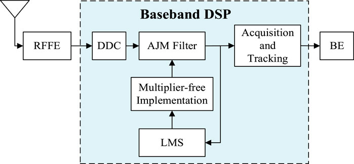
Figure 1. GNSS receiver structure.
Satellite navigation signals include the carrier, pseudo-random (PRN) code, and message data. The satellite navigation signal can be expressed by the carrier modulated with the spread spectrum signal of PRN code and data in Eq. 1:
where,
Suppose that the receiver thermal noise is
where,
The resultant input signal before the anti-jamming module can be expressed in Eq. 4 [25]:
2.2 Multiplier-free time-domain adaptive anti-jamming model
The time-domain anti-jamming algorithm utilizes the adaptive filter to suppress interference. The iterated filter coefficients should be implemented to be multiplier-free and then assigned to the weight storage module. Figure 2 illustrates the flow chart of the multiplier-free time-domain adaptive anti-jamming algorithm.
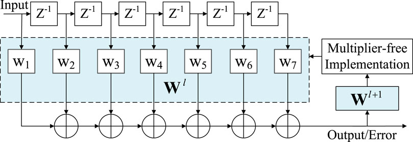
Figure 2. Anti-jamming flow chart with multiplier-free implementation.
Suppose that the input vector of the
Suppose the filter quantization bit width is L. The filter weight vector is as Eq. 6:
where,
Define the multiplier-free implementation method as
The error signal
The iterative formula of LMS algorithm can be expressed as Eq. 9 [26]:
where
The multiplier-free implementation of GNSS time-domain anti-jamming is applicable to satellite navigation receivers with limited hardware resources. For instance, mobile phones require the development of miniaturization capabilities and maintaining anti-interference capabilities, and spaceborne receivers’ functionality is expanded within the constraints of limited resources. Figure 3 depicts a ground-test module of a satellite-borne receiver in its practical application.
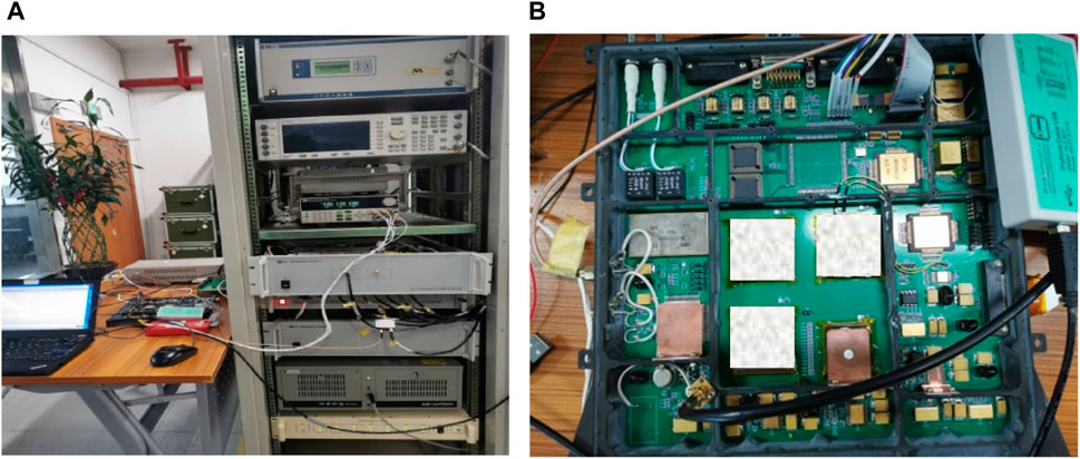
Figure 3. Practical application: ground-test module of spaceborne receiver. (A) Ground testing architecture. (B) Hardware development board.
3 Problem formulation
3.1 CSD coding
The signed number is one of the essential non-standard fixed-point number in computer algorithm implementation, and its digital range is
The CSD coding expresses the filter coefficients as the sum or difference of the power of 2, which is realized by shift operation and adder. The optimal CSD coding can also reduce the adder number and the maximum encoding lord length [27].
The mathematical expression of the FIR-filter anti-jamming can be simplified as shown in Eq. 10 [28]:
where,
CSD coding replaces all 1 sequences greater than 2 with
Suppose that the word length of the binary complement-on-two of value
where,
The word length of CSD encoding of value A is
where,
The binary complement is updated to CSD coding as shown from Eqs 14–16:
where,
Then optimize the CSD coding that may have storage waste by Eq. 17:
where,
Its update process can be expressed from Eqs 19–21:
where,
The number of adders is expressed as Eq. 22:
The number of shift operations is expressed as Eq. 23:
The figure shows the best CSD coding schematic. The value 211 is taken as an example in Figure 4, the multiplier-free design based on the optimal CSD coding is composed of 5 values of the power of 2, and the multiplication operation is realized by four adders and 18 shift operations.
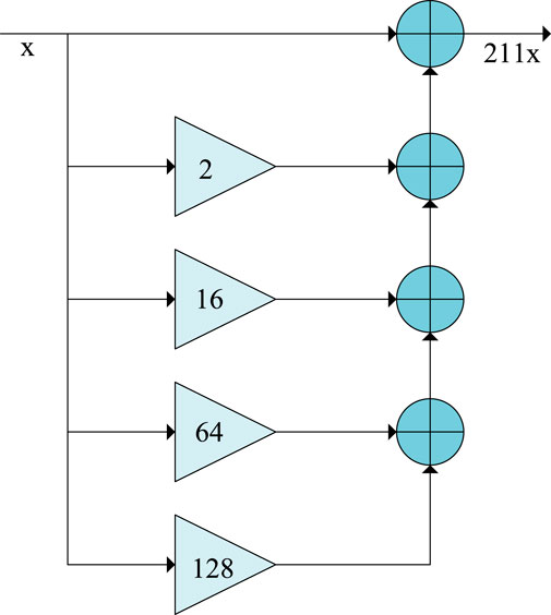
Figure 4. Optimal CSD coding schematic.
3.2 Numerical power decomposition
Numerical power decomposition is achieved by cascading several values to reduce the hardware cost of multiplier-less implementation [30]. For example, the traditional binary encoding of the value 231 is
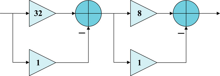
Figure 5. Numerical power decomposition schematic.
The value
where,
The numerical value will affect the device cost of the filter. The total adder number can be expressed as the sum of the number of adders required for different decomposition factors, as shown from Eqs 26–28:
where,
3.3 Motivations and optimization object
Static anti-jamming filters are usually used in power-sensitive terminals, and computational complexity is one of the most critical design elements. The effect of CSD optimal coding to reduce complexity is limited, and the existing numerical power decomposition is mainly the lookup table method. The accessible decomposition results are limited, creating difficulties for the multiplier-less implementation of large values.
Based on the disadvantages of optimal CSD coding and coefficient decomposition, in order to solve the problem of high gain in the actual filter coefficients, this paper proposes a cascaded multiplier-less implementation. The multiplier-less filter is implemented with minimum adders, reducing the shift operation and memory word length. The optimization objective is shown in Eq. 29:
4 Proposed approach
To design a multiplier-less anti-jamming filter, the numerical power decomposition of the filter coefficients is first performed to obtain each decomposition factor. The multiplier-less coding of all decomposition factors is designed according to the optimal CSD coding method. The flowchart is shown in Figure 6.
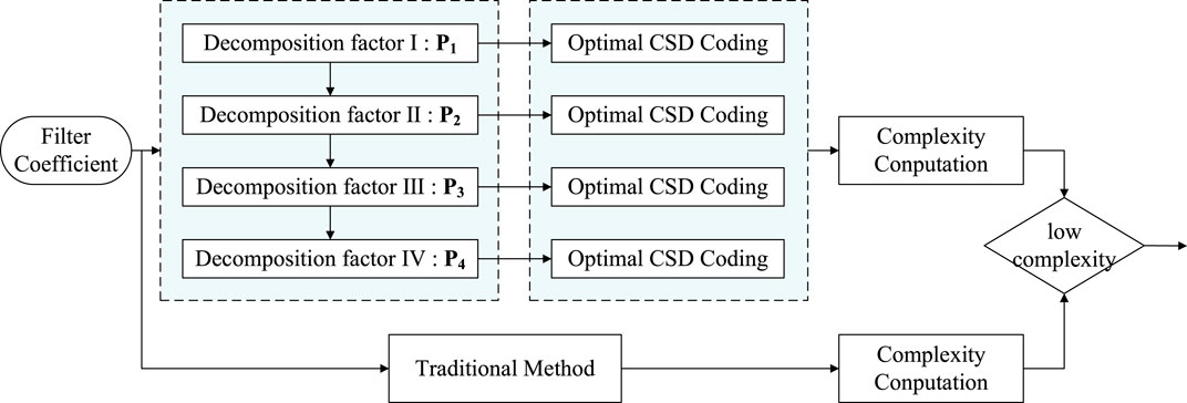
Figure 6. Cascaded multiplier-free implementation method flowchart.
Firstly, the numerical power decomposition of the filter coefficient
where,
Assume that
where,
Assume that
where,
Assume that
where,
The fourth decomposition factor
Define the multiplier-free implementation matrix is a cellular matrix as Eq. 38:
Based on complexity, a better multiplier-free implementation method is selected. In the decomposition process of any power factor
When Eqs 39, 40 is violated in any numerical power decomposition process, the numerical decomposition should be stopped. The decomposition process takes the last decomposition factor as the penultimate factor, and the remainder divided by the penultimate factor is recorded as the last factor. When the complexity of the cascaded multiplier-less implementation is higher than that of the traditional optimal CSD coding, the optimal CSD coding method is still used to achieve multiplication-free coefficients.
According to Eqs 7, 38, the logic circuit flow of anti-jamming output signal is derived in Eq. 41:
5 Performance analysis
5.1 Algorithm complexity comparison
Table 1 presents the complexity comparison between the proposed method and the traditional multiplier-free implementation method, considering the number of adders, shift operations, and maximum word length. The table displays the number of devices for various values under both multiplier-free implementation methods, highlighting the less complex approach. Compared to the traditional optimal CSD coding, the proposed method significantly reduces complexity in multiplier-free implementation. The number of adders is reduced by 0 or 1, while the number of shift operations and the maximum word length are reduced significantly by 13 and 2, respectively.
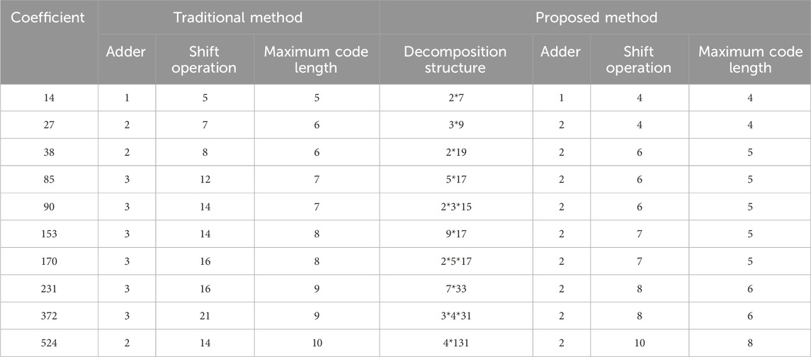
Table 1. Algorithm complexity comparison.
In order to verify the universal adaptability of the cascaded multiplier-less algorithm, the application rate and complexity optimization performance of the new algorithm with 1∼1,000 values is analyzed, respectively. Figure 7A shows the usage proportion of the proposed method. The total integer value of the coefficient is 1∼1,000, the smoothing point is set to 500, and the percentage of the cascade multiplier-less implementation is selected for each 400-point data calculation optimization method. The results show that as the coefficient increases, the optimization effect of the cascaded multiplier-less implementation method is better. Figure 7B demonstrates the smoothing result of the device reduction after using the proposed algorithm. Since the device complexity optimization results are relatively scattered, 59 is used as the smoothing unit to smooth the optimization data of adder, shift operation, and maximum coding word length, respectively. The results show that the cascade multiplier-free implementation method significantly reduces the number of the three devices on the graph. Among them, the number of shift operations decreases the most, and the maximum reduction reaches 19.
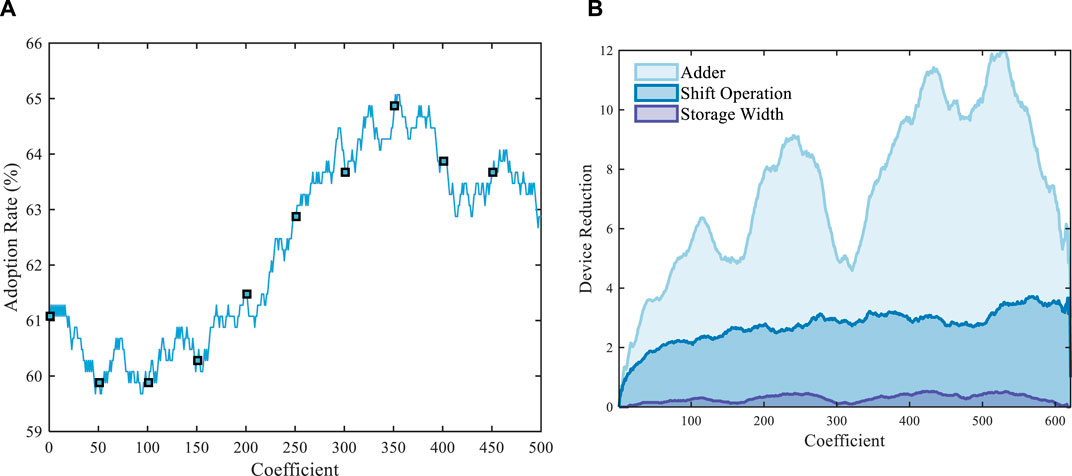
Figure 7. Universal adaptability analysis. (A) Usage proportion of the proposed method. (B) Complexity optimization performance.
The digital filters with lengths of 31 and 59 are designed by software. The filter quantization bit width is 12, and the initially designed filter is quantized. The optimization effect of the proposed method on the device complexity is verified based on the designed anti-jamming filter to ensure the effectiveness of the cascaded multiplier-free method in the GNSS receiver. Figure 8 shows that the optimal CSD coding method based on cascaded multiplier-free implementation reduces the multiplier and shift operations compared with CSD coding. After filter coefficient decomposition, the number of adders optimized by CSD coding is reduced by 0–2, and the shift operation is reduced by 0–5.

Figure 8. Complexity optimization comparison of different CSD codes based on factor cascade. (A) 30-order filter. (B) 58-order filter.
Figure 9 compares the anti-jamming filter complexity based on the cascaded multiplier-free implementation and the traditional method to verify the method availability. The results show that the adder reduction of the proposed method is greater than 0 compared with the traditional method, and the complexity reduction of the shift operation and the maximum code length is more pronounced. When the middle tap coefficient of the 58-order filter is 1,024, the number of shift operations is reduced by 20, and the maximum code length is reduced by 5.
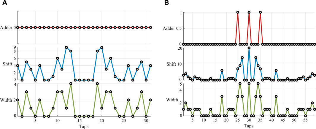
Figure 9. Comparison of device count between the proposed and traditional multiplier-free method. (A) 30-order filter. (B) 58-order filter.
Debugging and verification were performed on the test platform illustrated in Figure 3. By minimizing the number of effective operations, cascading multiplication-free processing was applied to the constant multiplier. The anti-jamming module achieved a 52% reduction in its effective circuit area.
5.2 Anti-jamming performance
The carrier-to-noise ratio (CNR) after interference mitigation is a quantitative assessment metric for evaluating time-domain interference resistance [32]. It is defined as the ratio of the carrier power to the power spectral density of the baseband signal noise. A too low carrier-to-noise ratio can severely affect the receiver’s ability to correctly capture and track. Carrier-to-noise ratio loss is the difference between the carrier-to-noise ratio under no-interference conditions and the carrier-to-noise ratio after interference mitigation defiened as Eq. 42.
Where,
A static filter with the navigation signal frequency as the stopband center frequency is designed, and the filter quantization bit width is set to 12. The carrier-to-noise ratio (CNR) of the BD3 signal is set to 50 dB·Hz, the interference bandwidth is 2MHz, the jamming-to-signal ratio (JSR) is 40dB, and the sampling rate of the software receiver is 25 MHz. The narrowband interference suppression performance based on the BD3 signal is shown in Figure 10. Figure 10A shows the spectrum before and after anti-jamming. The results show that the cascaded multiplier-free method can achieve anti-interference. The adaptive filter forms a null at least 30 dB in the interference frequency band. Figure 10B shows the navigation signal CNR after suppressing interference. The maximum CNR loss is less than 2 dB·Hz.
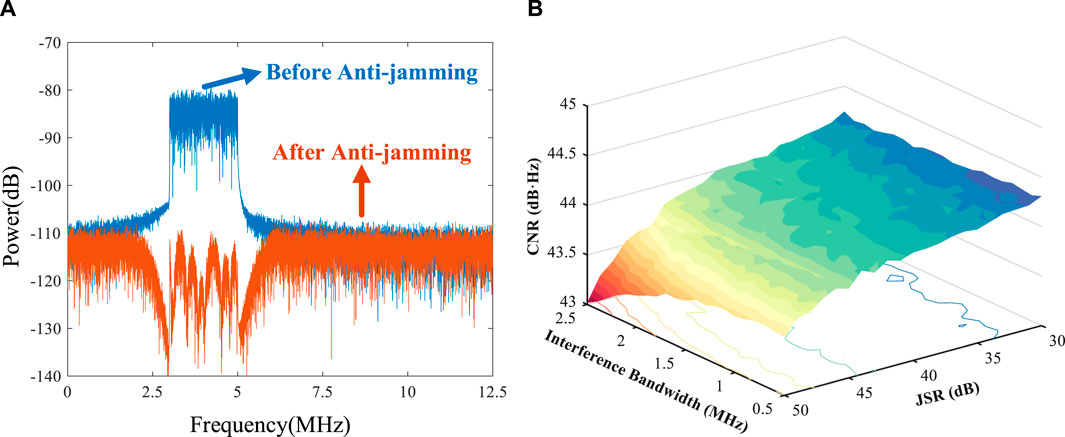
Figure 10. Interference suppression performance. (A) Spectrum diagram before and after anti-jamming. (B) Anti-jamming output CNR.
Figure 11 analyzes the ranging accuracy of the cascaded multiplication-free anti-interference method. Figure 11A displays the correlation function between the anti-interference output and the local signals. By observing the 10 chips surrounding the correlation peak, the correlation function of the output signal remains symmetric with the local signal, and the correlation peak position shows no obvious distortion. Figure 11B measures the symmetry of the correlation peak by the SCB curve bias and quantitatively analyzes the ranging deviation of the receiver [30]. Control the convergence step to reduce the influence of the time-varying filter on the ranging accuracy. Under a 31-order anti-interference filter, the pseudo-range measurement deviation is kept within 0.27 ns, which can ensure the ranging accuracy.
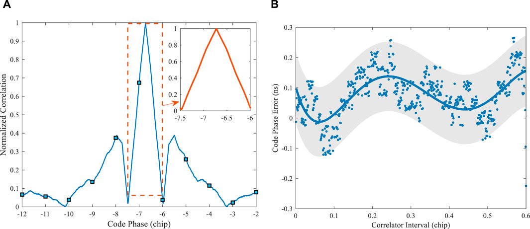
Figure 11. Measurement accuracy analysis. (A) The correlation function of the output and local signals. (B) SCB curve bias.
6 Conclusion
This paper introduces a cascaded multiplier-free implementation method and enhances the corresponding implementation scheme. This method is applied to the static time domain anti-jamming of GNSS receivers by replacing multipliers with a minimal number of adders and shift operations, utilizing optimal CSD coding and numerical power decomposition. Simulation results demonstrate that interference occupying 20% of the navigation signal bandwidth can be effectively suppressed, optimizing the anti-jamming filter structure. The number of adders, shift operations, and maximum code length are significantly reduced, with the maximum number of shift operations decreased by 20. The pseudo-range measurement accuracy has been verified to be within 0.27 ns, ensuring adequate ranging performance.
Data availability statement
The raw data supporting the conclusion of this article will be made available by the authors, without undue reservation.
Author contributions
JS: Writing–review and editing, Writing–original draft, Software, Methodology, Data curation. LC: Writing–review and editing, Writing–original draft, Methodology, Conceptualization. ZuL: Writing–review and editing, Methodology, Investigation, Funding acquisition, Conceptualization. BL: Writing–review and editing, Supervision, Investigation. ZhL: Writing–review and editing, Supervision, Formal Analysis, Data curation. ZX: Writing–review and editing, Visualization, Supervision, Software. GS: Writing–review and editing, Supervision, Resources, Project administration. WL: Writing–review and editing, Supervision, Resources, Investigation.
Funding
The authors declare that financial support was received for the research, authorship, and/or publication of this article. This research was funded by the National Natural Science Foundation of China (No. 62003354).
Acknowledgments
The authors would like to thank the editors and reviewers for their efforts to help the publication of this paper.
Conflict of interest
The authors declare that the research was conducted in the absence of any commercial or financial relationships that could be construed as a potential conflict of interest.
Publisher’s note
All claims expressed in this article are solely those of the authors and do not necessarily represent those of their affiliated organizations, or those of the publisher, the editors and the reviewers. Any product that may be evaluated in this article, or claim that may be made by its manufacturer, is not guaranteed or endorsed by the publisher.
References
1. Ferrara NG, Bhuiyan MZH, Söderholm S, Ruotsalainen L, Kuusniemi H. A new implementation of narrowband interference detection, characterization, and mitigation technique for a software-defined multi-gnss receiver. GPS Solutions (2018) 22(4):106. doi:10.1007/s10291-018-0769-z
2. Wang B, Sun Y, Liu Y, Zhang Y, Li S. Experimental research on narrowband interference suppression of gnss signals. Wireless Commun Mobile Comput (2021) 2021:3410741–12. doi:10.1155/2021/3410741
3. Zhao HZ, Wei GH, Pan XD. Evaluation method of noise electromagnetic radiation interference effect. IEEE Trans Electromagn Compatibility (2023) 65(1):69–78. doi:10.1109/TEMC.2022.3224791
4. Falletti E, Gamba MT, Pini M. Design and analysis of activation strategies for adaptive notch filters to suppress gnss jamming. IEEE Trans Aerospace Electron Syst (2020) 56(5):3718–34. doi:10.1109/TAES.2020.2982301
5. Ying L, Wei T, Zhixiong W. The frequency spectrum management for aerospace tt&C system. In: 2013 5th IEEE International Symposium on Microwave, Antenna, Propagation and EMC Technologies for Wireless Communications; 29-31 October 2013; Chengdu, China (2013).
6. Chien Y-R. Design of GPS anti-jamming systems using adaptive notch filters. IEEE Syst J (2015) 9(9):451–60. doi:10.1109/JSYST.2013.2283753
7. Ren Y, Zhi Y, Gao H, Zhang J. Performance analysis of subspace projection algorithm with respect to projection length for GNSS jamming mitigation. Digit Signal Process (2023) 142:104212. doi:10.1016/j.dsp.2023.104212
8. Wang H, Chang Q, Xu Y, Li X. Adaptive narrow-band interference suppression and performance evaluation based on code-aided in GNSS inter-satellite links. IEEE Syst J (2020) 14:538–47. doi:10.1109/JSYST.2019.2918055
9. Xu D, Yin B, Wang W, Zhu W. Variable tap-length lms algorithm based on adaptive parameters for tdl structure adaption. IEEE Signal Process. Lett (2014) 21(7):809–13. doi:10.1109/LSP.2014.2317752
10. Liu J, Grant SL. Proportionate adaptive filtering for block-sparse system identification. IEEE/ACM Trans Audio, Speech, Lang Process (2016) 24(4):623–30. doi:10.1109/TASLP.2015.2499602
11. Chen W, Huang M, Lou X. Design of sparse fir filters with reduced effective length. IEEE Trans Circuits Syst Regular Pap (2019) 66(4):1496–506. doi:10.1109/TCSI.2018.2883965
12. Garcia R, Volkova A. Toward the multiple constant multiplication at minimal hardware cost. IEEE Trans Circuits Syst Regular Pap (2023) 70(5):1976–88. doi:10.1109/TCSI.2023.3241859
13. Lakshmi V, Pudi V, Reuben J. Inner product computation in-memory using distributed arithmetic. IEEE Trans Circuits Syst Regular Pap (2022) 69(11):4546–57. doi:10.1109/TCSI.2022.3193678
14. Aksoy L, Roy DB, Imran M, Karl P, Pagliarini S. Multiplierless design of very large constant multiplications in cryptography. IEEE Trans Circuits Syst Express Briefs (2022) 69(11):4503–7. doi:10.1109/TCSII.2022.3191662
15. Mohamed SM, Sayed WS, Radwan AG, Said LA. Fpga implementation of reconfigurable cordic algorithm and a memristive chaotic system with transcendental nonlinearities. IEEE Trans Circuits Syst Regular Pap (2022) 69(7):2885–92. doi:10.1109/TCSI.2022.3165469
16. Ye WB, Yu YJ. Bit-level multiplierless fir filter optimization incorporating sparse filter technique. IEEE Trans Circuits Syst Regular Pap (2014) 61(11):3206–15. doi:10.1109/TCSI.2014.2327287
17. Kumm M, Volkova A, Filip SI. Design of optimal multiplierless fir filters with minimal number of adders. IEEE Trans Computer-Aided Des Integrated Circuits Syst (2023) 42(2):658–71. doi:10.1109/TCAD.2022.3179221
18. Samueli H. An improved search algorithm for the design of multiplierless fir filters with powers-of-two coefficients. IEEE Trans Circuits Syst (1989) 36(7):1044–7. doi:10.1109/31.31347
19. Thong J, Nicolici N Combined optimal and heuristic approaches for multiple constant multiplication (2010). p. 266–73.
20. Aktan M, Yurdakul A, Dundar G. An algorithm for the design of low-power hardware-efficient fir filters. IEEE Trans Circuits Syst Regular Pap (2008) 55(6):1536–45. doi:10.1109/TCSI.2008.917997
21. Shahein A, Zhang Q, Lotze N, Manoli Y. A novel hybrid monotonic local search algorithm for fir filter coefficients optimization. IEEE Trans Circuits Syst Regular Pap (2012) 59(3):616–27. doi:10.1109/TCSI.2011.2165409
22. Song J, Lu Z, Xiao Z, Li B, Sun G. Optimal order of time-domain adaptive filter for anti-jamming navigation receiver. Remote Sensing (2022) 14(1):48. doi:10.3390/rs14010048
23. Lv Q, Qin H. General method to mitigate the continuous wave interference and narrowband interference for gnss receivers. IET Radar, Sonar & Navigation (2020) 14(9):1430–5. doi:10.1049/iet-rsn.2020.0115
24. Mosavi MR, Shafiee F. Narrowband interference suppression for gps navigation using neural networks. GPS Solutions (2016) 20(3):341–51. doi:10.1007/s10291-015-0442-8
25. Elghamrawy H, Karaim M, Tamazin M, Noureldin A. Experimental evaluation of the impact of different types of jamming signals on commercial gnss receivers. Appl Sci (2020) 10(12):4240. (2076-3417). doi:10.3390/app10124240
26. Li B, Qiao J, Lu Z, Yu X, Song J, Lin B, et al. Influence of sweep interference on satellite navigation time-domain anti-jamming. Front Phys (2023) 10. doi:10.3389/fphy.2022.1063474
27. He Y, Zhang Z, Ma B, Li J, Zhen S, Luo P, et al. A fast and energy efficient binary-to-pseudo csd converter. In: 2015 IEEE International Symposium on Circuits and Systems (ISCAS); 24-27 May 2015 (2015). doi:10.1109/iscas.2015.7168764
28. Saneei M, Afzali-Kusha A, Navabi Z. A low power technique based on sign bit reduction. In: Proceedings The 16th International Conference on Microelectronics, 2004 ICM 2004; 6-8 Dec. 2004 (2004).
29. Cai L, Qian Y, He Y, Feng W. Design of approximate multiplierless dct with csd encoding for image processing. In: 2021 IEEE International Symposium on Circuits and Systems (ISCAS); 22-28 May 2021 (2021). doi:10.1109/iscas51556.2021.9401200
30. Erdogan AT, Arslan T. A coefficient segmentation algorithm for low power implementation of fir filters. In: 1999 IEEE International Symposium on Circuits and Systems (ISCAS); 30 May-2 June 1999 (1999).
31. Saneei M, Afzali-Kusha A, Navabi Z. Sign bit reduction encoding for low power applications. In: Proceedings 42nd Design Automation Conference; 13-17 June 2005 (2005).
Keywords: GNSS receiver, time domain anti-interference, optimal CSD coding, numerical power decomposition, cascaded multiplier-free implementation
Citation: Song J, Chen L, Lu Z, Li B, Liu Z, Xue Z, Sun G and Liu W (2024) Cascaded multiplier-free implementation of adaptive anti-jamming filter based on GNSS receiver. Front. Phys. 12:1404236. doi: 10.3389/fphy.2024.1404236
Received: 20 March 2024; Accepted: 28 May 2024;
Published: 03 July 2024.
Edited by:
Jiansen He, Peking University, ChinaCopyright © 2024 Song, Chen, Lu, Li, Liu, Xue, Sun and Liu. This is an open-access article distributed under the terms of the Creative Commons Attribution License (CC BY). The use, distribution or reproduction in other forums is permitted, provided the original author(s) and the copyright owner(s) are credited and that the original publication in this journal is cited, in accordance with accepted academic practice. No use, distribution or reproduction is permitted which does not comply with these terms.
*Correspondence: Zukun Lu, bHV6dWt1bkBudWR0LmVkdS5jbg==; Zhe Liu, bF96QG51ZHQuZWR1LmNu
†These authors have contributed equally to this work