
94% of researchers rate our articles as excellent or good
Learn more about the work of our research integrity team to safeguard the quality of each article we publish.
Find out more
ORIGINAL RESEARCH article
Front. Phys., 30 July 2024
Sec. Medical Physics and Imaging
Volume 12 - 2024 | https://doi.org/10.3389/fphy.2024.1401834
This article is part of the Research TopicChallenges in VHEE RadiotherapyView all 10 articles
 James Cayley1*
 Yaw-Ren E. Tan2
 Marco Petasecca1
 Dean Cutajar1Thomas Breslin3
 Anatoly Rosenfeld1
 Michael Lerch1
FLASH radiotherapy, which refers to the delivery of radiation at ultra-high dose-rates (UHDRs), has been demonstrated with various forms of radiation and is the subject of intense research and development recently, including the use of very high-energy electrons (VHEEs) to treat deep-seated tumors. Delivering FLASH radiotherapy in a clinical setting is expected to place high demands on real-time quality assurance and dosimetry systems. Furthermore, very high-energy electron research currently requires the transformation of existing non-medical accelerators into radiotherapy research environments. Accurate dosimetry is crucial for any such transformation. In this article, we assess the response of the MOSkin, developed by the Center for Medical Radiation Physics, which is designed for on-patient, real-time skin dose measurements during radiotherapy, and whether it exhibits dose-rate independence when exposed to 100 MeV electron beams at the Pulsed Energetic Electrons for Research (PEER) end-station. PEER utilizes the electron beam from a 100 MeV linear accelerator when it is not used as the injector for the ANSTO Australian Synchrotron. With the estimated pulse dose-rates ranging from
FLASH radiotherapy is an emerging cancer treatment modality that utilises much higher dose-rates than conventional radiotherapy. Recent evidence published indicates that delivering radiation with ultra-high dose-rates (UHDRs) results in a so-called “FLASH effect,” whereby healthy tissue is spared and the effects on normal bodily function are reduced while maintaining adequate tumor control [1–5]. The FLASH effect has been demonstrated at average treatment dose-rates
Converted medical linear accelerators (linacs) are being used to deliver UHDR electrons. To provide the required dose-rates, the conversion often requires the removal or modification of transmission ion chambers in the head of the linac [10–12] that are used for beam interruption if the radiation delivery diverges from the treatment plan. In the absence of traditional beam interruption systems, there have been advances in fluence monitoring using beam current transformers and pulse delivery optimization systems [13–15]. However, while such advances have been successful and are very important tools for monitoring the delivery of radiation by the linac, these are not forms of dosimetry and so should not be used in isolation for quality assurance. Malfunctioning or mispositioned linac components, such as the jaws or multi-leaf-collimator, installed after the target will cause changes in the dose that are not reflected in the linac beam current.
A critical metric for any external beam radiotherapy modality is the true dose delivered to the patient, often inferred from in vivo dosimetry by measuring the dose to the skin, which is itself an important metric [16, 17]. Radiotherapy, of differing types and energies, delivers a dose to the patient’s skin that may be high or low relative to the point of maximum dose. When discussing skin dose, the region of interest is the radio-sensitive basal cell layer that resides at the inner-most end of the epidermis at an average depth of 70 µm [16–18]. Although future VHEE treatments may deliver a low skin dose relative to the maximum dose [19–21], the dose should be quantified via in vivo measurements and can be used for quality assurance during patient treatment. Current UHDR dosimetry mostly relies upon GafChromic film [11, 22, 23], although other forms of dosimetry such as calorimeters and modified ionization chambers have also been successfully demonstrated as suitable [24, 25]. However, these forms of dosimetry either require complicated setups, lack the near real-time results highly desired in a clinical setting, or are not suitable for evaluating skin dose during treatment delivery. Metal oxide semiconductor field effect transistor (MOSFET) dosimeters offer a promising solution for UHDR environments, which are known for their dose-rates independence, having previously been tested using an electron linac with dose-rates up to
Modern medical linacs deliver pulsed electron beams that consist of a sub-structure of electron bunches [40, 41]. Therefore, when discussing dose-rates for medical purposes, not only
For an in-depth discussion of the general construction and operation of MOSFET detectors, please refer to [43]. The MOSkins are exposed to the VHEE irradiation field, creating electron–hole pairs in the gate oxide
The VHEE beam at PEER features a custom-built research linac, which is normally used to inject bunched
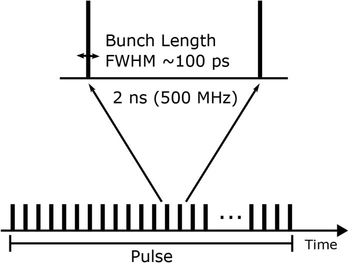
Figure 1. Electron linac pulses consist of an underlying bunch structure. PEER parameters are shown.
Two MOSkin detectors (Detectors 1 and 2 shown in Figure 2A) were mounted on a

Figure 2. (A) Array design with MOSkins overlaid for clarity. Unless otherwise stated, dimensions are in mm. (B) Camera image showing scintillating screen with arrows indicating the center of array alignment.
During the timeframe in which the following experiment was conducted, pulses consisting of
Before dosimetry commenced, the VHEE beam was aligned with the center of the scintillator using the arrows visible in Figure 2B, as this was aligned to the array of MOSkins. After beam alignment, single
An average of
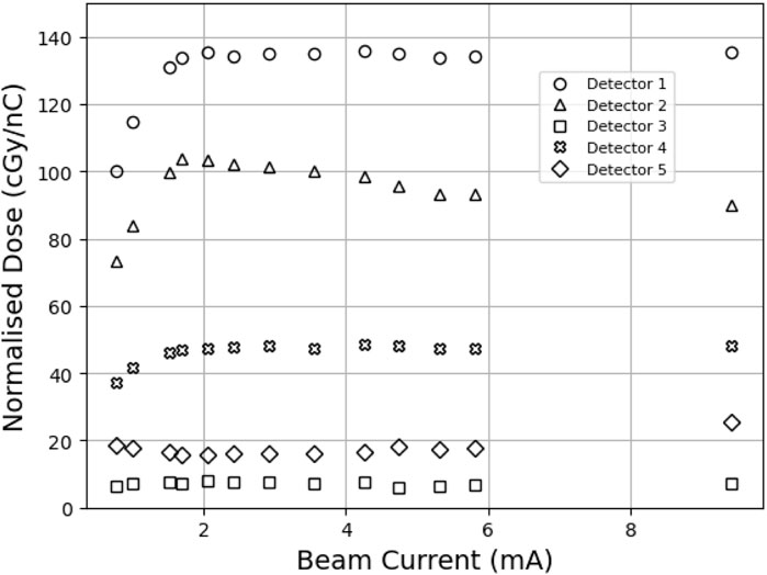
Figure 3. MOSkin responses converted to dose and normalized to charge as measured by FCT. A
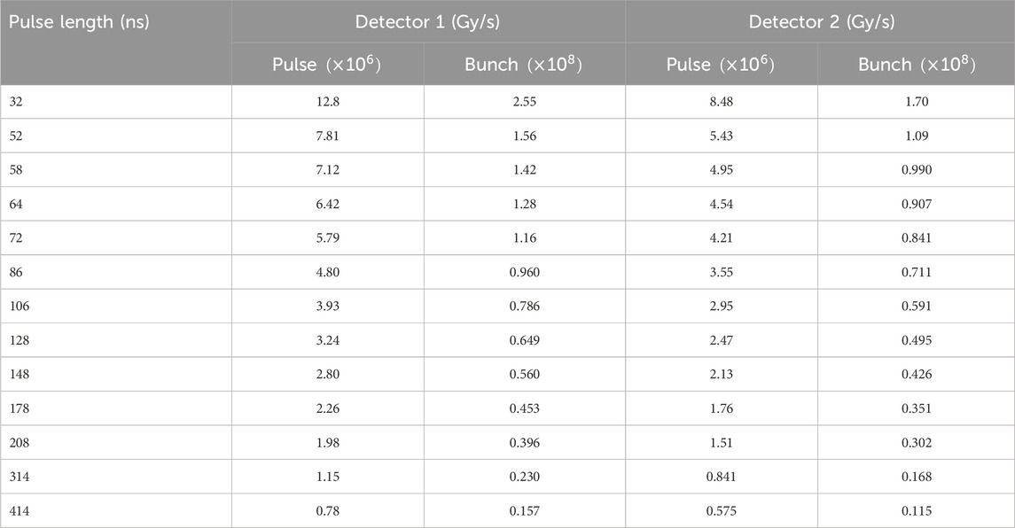
Table 1. Estimated mean
Using spatial information gained from the array, beam profiles were created from the scintillator data using ImageJ software [46] at the estimated vertical location of Detectors 1 and 2. Typically, a Gaussian distribution would be fitted to beam profiles; however, this was not a good fit for the PEER beam due to high dose gradients in the penumbra region. Instead, a Moffat distribution was used. The Moffat distribution is a modified Lorentzian distribution created to model point-source astronomical objects with steep fall-off gradients [47], which is defined as
where
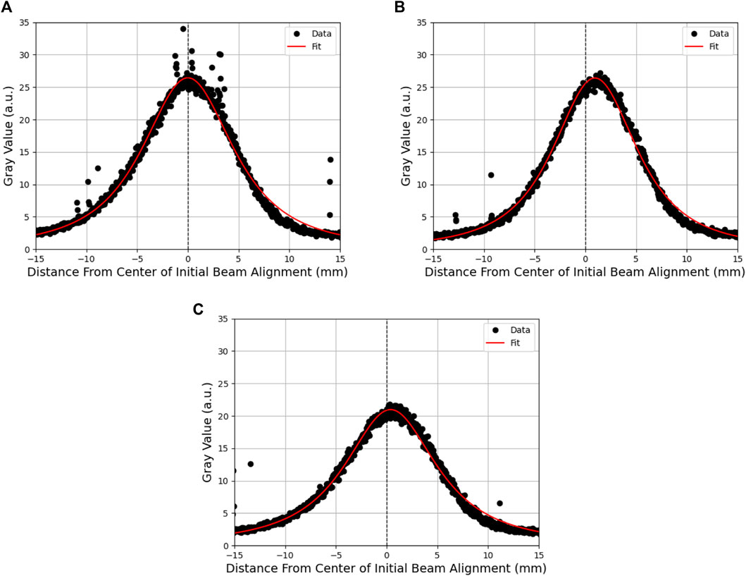
Figure 4. Moffat distribution fitted to scintillator beam profiles of a single pulse at a (A) high beam current, (B) the point at which detector response begins to fall off, and (C) low beam current. The difference in intensity between high and low beam currents is visible as a reduction in the magnitude of the profile and the movement of the beam from the initial alignment.
To assess the behavior of Detector 2, the value was extracted at a fixed point
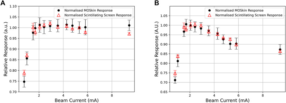
Figure 5. (A,B) Relative response of each pulse between the MOSkin and scintillating screen for Detector 1 and Detector 2, respectively.
Due to the design of the array (Figure 2A), the two central detectors should respond equally if the array were aligned perfectly to the beam, and the out-of-field detectors 3, 4, and 5 should also exhibit an equal response due to the Gaussian-like distribution of electron beams combined with the radial symmetry of the detector positioning on the array. The relative response between detectors, as shown in Figure 3, indicates a misalignment consistent with the position of the array relative to the central beam axis. This misalignment is also shown in Figure 2B, where the arrows marked on the scintillator reflect the vertical and horizontal positioning of the center of the array; the scintillator shows a response consistent with the findings from the relative MOSkin responses. Detector 5 responses decreased as the beam current decreased, in contrast to Detector 2, indicating that the beam also shifted horizontally throughout the experiment. Throughout the analysis,
The observed fall-off in the MOSkin response below 2 mA indicates either an incorrect response from the MOSkins or an error in charge delivery to the experimental stage. However, after analyzing the scintillator response and comparing the normalized data shown in Figure 5, it is clear that this fall-off is common to both instruments and must be due to a loss of charge from the linac rather than an incorrect reading from the MOSkins. These results indicate that the MOSkin responds proportionally to the charge delivered to the experimental stage rather than changing beam current and thus exhibits dose-rate independence when exposed to the VHEE beam at PEER.
Of further importance is the discovery of the limitations of the FCT. Although the PEER FCT was originally commissioned to monitor beam currents during daily AS operation, this work provides important insight into the potential limitations of such devices. With efforts being made to correlate dose delivery to beam current transformers and other fluence monitoring devices on existing and new linacs for UHDR RT, these results suggest a requirement for accurate quality assurance dosimetry in conjunction with online monitoring devices as part of any future UHDR VHEE quality assurance.
While being exposed to
The raw data supporting the conclusions of this article will be made available by the authors, without undue reservation.
JC: conceptualization, formal analysis, investigation, methodology, visualization, writing–original draft, and writing–review and editing. Y-RT: conceptualization, data curation, investigation, methodology, resources, software, supervision, and writing–review and editing. MP: conceptualization, investigation, methodology, and writing–review and editing. DC: conceptualization, investigation, methodology, and writing–review and editing. TB: conceptualization, investigation, methodology, and writing–review and editing. AR: conceptualization, funding acquisition, investigation, methodology, resources, supervision, and writing–review and editing. ML: conceptualization, funding acquisition, investigation, methodology, resources, supervision, and writing–review and editing.
The authors declare that financial support was received for the research, authorship, and/or publication of this article. JC received Australian Government RTP scholarship APP505948.
This research was undertaken on the PEER beamline, Australian Synchrotron, part of ANSTO. The authors would like to thank Khonraed Gill for the creation of engineering drawings and STEP files.
ML, AR, MP, and DC declare consulting with Electrogenics Laboratories Ltd., which is commercializing the MOSkin detector.
The remaining authors declare that the research was conducted in the absence of any commercial or financial relationships that could be construed as a potential conflict of interest.
The authors declared that they were an editorial board member of Frontiers, at the time of submission. This had no impact on the peer review process and the final decision.
All claims expressed in this article are solely those of the authors and do not necessarily represent those of their affiliated organizations, or those of the publisher, the editors, and the reviewers. Any product that may be evaluated in this article, or claim that may be made by its manufacturer, is not guaranteed or endorsed by the publisher.
1. Favaudon V, Caplier L, Monceau V, Pouzoulet F, Sayarath M, Fouillade C, et al. Ultrahigh dose-rate FLASH irradiation increases the differential response between normal and tumor tissue in mice. Sci Translational Med (2014) 6:245ra93. doi:10.1126/scitranslmed.3008973
2. Montay-Gruel P, Acharya MM, Gonçalves Jorge P, Petit B, Petridis IG, Fuchs P, et al. Hypofractionated FLASH-RT as an effective treatment against glioblastoma that reduces neurocognitive side effects in mice. Clin Cancer Res (2021) 27:775–84. doi:10.1158/1078-0432.CCR-20-0894
3. Chabi S, To THV, Leavitt R, Poglio S, Jorge PG, Jaccard M, et al. Ultra-high-dose-rate FLASH and conventional-dose-rate irradiation differentially affect human acute lymphoblastic leukemia and normal hematopoiesis. Int J Radiat Oncol - Biol - Phys (2021) 109:819–29. doi:10.1016/j.ijrobp.2020.10.012
4. Simmons DA, Lartey FM, Schüler E, Rafat M, King G, Kim A, et al. Reduced cognitive deficits after FLASH irradiation of whole mouse brain are associated with less hippocampal dendritic spine loss and neuroinflammation. FLASH Radiother Int Workshop (2019) 139:4–10. doi:10.1016/j.radonc.2019.06.006
5. Vozenin MC, De Fornel P, Petersson K, Favaudon V, Jaccard M, Germond JF, et al. The advantage of FLASH radiotherapy confirmed in mini-pig and cat-cancer patients. Clin Cancer Res (2019) 25:35–42. doi:10.1158/1078-0432.CCR-17-3375
6. Lin B, Gao F, Yang Y, Wu D, Zhang Y, Feng G, et al. FLASH radiotherapy: history and future. Front Oncol (2021) 11:644400. doi:10.3389/fonc.2021.644400
7. Atkinson J, Bezak E, Le H, Kempson I. The current status of FLASH particle therapy: a systematic review. Phys Eng Sci Med (2023) 46:529–60. doi:10.1007/s13246-023-01266-z
8. Sarti A, De Maria P, Battistoni G, De Simoni M, Di Felice C, Dong Y, et al. Deep seated tumour treatments with electrons of high energy delivered at FLASH rates: the example of prostate cancer. Front Oncol (2021) 11:777852. doi:10.3389/fonc.2021.777852
9. Böhlen TT, Germond JF, Traneus E, Bourhis J, Vozenin MC, Bailat C, et al. Characteristics of very high-energy electron beams for the irradiation of deep-seated targets. Med Phys (2021) 48:3958–67. doi:10.1002/mp.14891
10. Giuliano L, Franciosini G, Palumbo L, Aggar L, Dutreix M, Faillace L, et al. Characterization of ultra-high-dose rate electron beams with ElectronFlash linac. Appl Sci (2023) 13:631. doi:10.3390/app13010631
11. Lempart M, Blad B, Adrian G, Bäck S, Knöös T, Ceberg C, et al. Modifying a clinical linear accelerator for delivery of ultra-high dose rate irradiation. Radiother Oncol (2019) 139:40–5. doi:10.1016/j.radonc.2019.01.031
12. Rahman M, Ashraf MR, Zhang R, Bruza P, Dexter CA, Thompson L, et al. Electron FLASH delivery at treatment room isocenter for efficient reversible conversion of a clinical LINAC. Int J Radiat Oncol - Biol - Phys (2021) 110:872–82. doi:10.1016/j.ijrobp.2021.01.011
13. Gonçalves Jorge P, Grilj V, Bourhis J, Vozenin MC, Germond JF, Bochud F, et al. Technical note: validation of an ultrahigh dose rate pulsed electron beam monitoring system using a current transformer for FLASH preclinical studies. Med Phys (2022) 49:1831–8. doi:10.1002/mp.15474
14. Jain S, Cetnar A, Woollard J, Gupta N, Blakaj D, Chakravarti A, et al. Pulse parameter optimizer: an efficient tool for achieving prescribed dose and dose rate with electron FLASH platforms. Phys Med Biol (2023) 68:19NT01. doi:10.1088/1361-6560/acf63e
15. Vignati A, Giordanengo S, Fausti F, Martì Villarreal OA, Mas Milian F, Mazza G, et al. Beam monitors for tomorrow: the challenges of electron and photon FLASH RT. Front Phys (2020) 8. doi:10.3389/fphy.2020.00375
16. Qi ZY, Deng XW, Huang SM, Zhang L, He ZC, Allen Li X, et al. In vivo verification of superficial dose for head and neck treatments using intensity-modulated techniques. Med Phys (2009) 36:59–70. doi:10.1118/1.3030951
17. McDermott PN. Surface dose and acute skin reactions in external beam breast radiotherapy. Med Dosimetry (2020) 45:153–8. doi:10.1016/j.meddos.2019.09.001
18. Valentin J. Basic anatomical and physiological data for use in radiological protection: reference values: ICRP Publication 89: approved by the Commission in September 2001. Ann ICRP (2002) 32:1–277. doi:10.1016/S0146-6453(03)00002-2
19. Ronga MG, Cavallone M, Patriarca A, Leite AM, Loap P, Favaudon V, et al. Back to the future: very high-energy electrons (VHEEs) and their potential application in radiation therapy. Cancers (2021) 13:4942. doi:10.3390/cancers13194942
20. DesRosiers C, Moskvin V, Bielajew AF, Papiez L. 150-250 MeV electron beams in radiation therapy. Phys Med Biol (2000) 45:1781–805. doi:10.1088/0031-9155/45/7/306
21. Papiez L, DesRosiers C, Moskvin V. Very high energy electrons (50-250 MeV) and radiation therapy. Technol Cancer Res Treat (2002) 1:105–10. doi:10.1177/153303460200100202
22. Szpala S, Huang V, Zhao Y, Kyle A, Minchinton A, Karan T, et al. Dosimetry with a clinical linac adapted to FLASH electron beams. J Appl Clin Med Phys (2021) 22:50–9. doi:10.1002/acm2.13270
23. Jaccard M, Durán MT, Petersson K, Germond JF, Liger P, Vozenin MC, et al. High dose-per-pulse electron beam dosimetry: commissioning of the Oriatron eRT6 prototype linear accelerator for preclinical use. Med Phys (2018) 45:863–74. doi:10.1002/mp.12713
24. Gómez F, Gonzalez-Castaño DM, Fernández NG, Pardo-Montero J, Schüller A, Gasparini A, et al. Development of an ultra-thin parallel plate ionization chamber for dosimetry in FLASH radiotherapy. Med Phys (2022) 49:4705–14. doi:10.1002/mp.15668
25. Bass GA, Shipley DR, Flynn SF, Thomas RAS. A prototype low-cost secondary standard calorimeter for reference dosimetry with ultra-high pulse dose rates. Br J Radiol (2023) 96:20220638. doi:10.1259/bjr.20220638
26. Fleetwood D, Winokur P, Schwank J. Using laboratory X-ray and cobalt-60 irradiations to predict CMOS device response in strategic and space environments. IEEE Trans Nucl Sci (1988) 35:1497–505. doi:10.1109/23.25487
27. Kwan I, Rosenfeld A, Qi Z, Wilkinson D, Lerch M, Cutajar D, et al. Skin dosimetry with new MOSFET detectors. Radiat Measurements (2008) 43:929–32. doi:10.1016/j.radmeas.2007.12.052
28. Patterson E, Stokes P, Cutajar D, Rosenfeld A, Baines J, Metcalfe P, et al. High-resolution entry and exit surface dosimetry in a 1.5 T MR-linac. Phys Eng Sci Med (2023) 46:787–800. doi:10.1007/s13246-023-01251-6
29. Tai M, Patterson E, Metcalfe PE, Rosenfeld A, Oborn BM. Skin dose modeling and measurement in a high field in-line MRI-linac system. Front Phys (2022) 10. doi:10.3389/fphy.2022.902744
30. Thorpe NK, Cutajar D, Lian C, Pitney M, Friedman D, Perevertaylo V, et al. A comparison of entrance skin dose delivered by clinical angiographic c-arms using the real-time dosimeter: the MOSkin. Australas Phys Eng Sci Med (2016) 39:423–30. doi:10.1007/s13246-016-0435-0
31. Alnawaf H, Butson M, Yu PKN. Measurement and effects of MOSKIN detectors on skin dose during high energy radiotherapy treatment. Australas Phys Eng Sci Med (2012) 35:321–8. doi:10.1007/s13246-012-0153-1
32. Souris JS, Cheng SH, Pelizzari C, Chen NT, La Riviere P, Chen CT, et al. Radioluminescence characterization of in situ x-ray nanodosimeters: potential real-time monitors and modulators of external beam radiation therapy. Appl Phys Lett (2014) 105:203110. doi:10.1063/1.4900962
33. Jornet N, Carrasco P, Jurado D, Ruiz A, Eudaldo T, Ribas M. Comparison study of MOSFET detectors and diodes for entrance in vivo dosimetry in 18 MV x-ray beams. Med Phys (2004) 31:2534–42. doi:10.1118/1.1785452
34. Fleetwood DM. Perspective on radiation effects in nanoscale metal–oxide–semiconductor devices. Appl Phys Lett (2022) 121:070503. doi:10.1063/5.0105173
35. Rosenfeld AB. MOSFET dosimetry on modern radiation oncology modalities. Radiat Prot Dosimetry (2002) 101:393–8. doi:10.1093/oxfordjournals.rpd.a006009
36. Qi ZY, Deng XW, Huang SM, Lu J, Lerch M, Cutajar D, et al. Verification of the plan dosimetry for high dose rate brachytherapy using metal–oxide–semiconductor field effect transistor detectors. Med Phys (2007) 34:2007–13. doi:10.1118/1.2736288
37. Jong W, Ung N, Tiong A, Rosenfeld A, Wong J. Characterisation of a MOSFET-based detector for dose measurement under megavoltage electron beam radiotherapy. Radiat Phys Chem (2018) 144:76–84. doi:10.1016/j.radphyschem.2017.11.021
38. Choi JH, Cutajar D, Metcalfe P, Downes S. Application of MOSkin detector for in vivo dosimetry on total skin electron therapy (TSET). Biomed Phys Eng Express (2018) 4:024002. doi:10.1088/2057-1976/aaac61
39. Shepard AJ, Matrosic CK, Radtke JL, Jupitz SA, Culberson WS, Bednarz BP. Technical Note: characterization of clinical linear accelerator triggering latency for motion management system development. Med Phys (2018) 45:4816–21. doi:10.1002/mp.13191
40. Metcalfe P, Kron T, Hoban P, Cutajar D, Hardcastle N. The Physics of radiotherapy X-rays and electrons. 3rd ed. Madison, WI: Medical Physics Publishing (2023).
41. Romano F, Bailat C, Jorge PG, Lerch MLF, Darafsheh A. Ultra-high dose rate dosimetry: challenges and opportunities for FLASH radiation therapy. Med Phys (2022) 49:4912–32. doi:10.1002/mp.15649
42. Di Martino F, Barca P, Barone S, Bortoli E, Borgheresi R, De Stefano S, et al. FLASH radiotherapy with electrons: issues related to the production, monitoring, and dosimetric characterization of the beam. Front Phys (2020) 8. doi:10.3389/fphy.2020.570697
43. Oldham TR. Ionizing radiation effects in MOS oxides. In: International series on advances in solid state electronics and technology. World Scientific (2000). doi:10.1142/3655
44. Jong WL, Wong J, Ung NM, Ng KH, Ho G, Cutajar D, et al. Characterization of MOSkin detector for in vivo skin dose measurement during megavoltage radiotherapy. J Appl Clin Med Phys/Am Coll Med Phys (2014) 15:120–32. doi:10.1120/jacmp.v15i5.4869
45. Meier E, Dowd R, LeBlanc G. Characterization of the Australian synchrotron linac. Nucl Instr Methods Phys Res Section A: Acc Spectrometers, Detectors Associated Equipment (2008) 589:157–66. doi:10.1016/j.nima.2008.02.009
46. Schneider CA, Rasband WS, Eliceiri KW. NIH Image to ImageJ: 25 years of image analysis. Nat Methods (2012) 9:671–5. doi:10.1038/nmeth.2089
Keywords: skin dose, FLASH, dosimetry, very high-energy electrons, MOSkin, ultra-high dose-rate, VHEE
Citation: Cayley J, Tan Y-RE, Petasecca M, Cutajar D, Breslin T, Rosenfeld A and Lerch M (2024) MOSkin dosimetry for an ultra-high dose-rate, very high-energy electron irradiation environment at PEER. Front. Phys. 12:1401834. doi: 10.3389/fphy.2024.1401834
Received: 16 March 2024; Accepted: 04 July 2024;
Published: 30 July 2024.
Edited by:
Angeles Faus Golfe, UMR9012 Laboratoire de Physique des 2 infinis Irène Joliot-Curie (IJCLab), FranceReviewed by:
Lanchun Lu, The Ohio State University, United StatesCopyright © 2024 Cayley, Tan, Petasecca, Cutajar, Breslin, Rosenfeld and Lerch. This is an open-access article distributed under the terms of the Creative Commons Attribution License (CC BY). The use, distribution or reproduction in other forums is permitted, provided the original author(s) and the copyright owner(s) are credited and that the original publication in this journal is cited, in accordance with accepted academic practice. No use, distribution or reproduction is permitted which does not comply with these terms.
*Correspondence: James Cayley, amNheWxleUB1b3cuZWR1LmF1
Disclaimer: All claims expressed in this article are solely those of the authors and do not necessarily represent those of their affiliated organizations, or those of the publisher, the editors and the reviewers. Any product that may be evaluated in this article or claim that may be made by its manufacturer is not guaranteed or endorsed by the publisher.
Research integrity at Frontiers
Learn more about the work of our research integrity team to safeguard the quality of each article we publish.