 Keyao Song
 Han Li
 Yang Li
 Jiayao Ma3
 Xiang Zhou
94% of researchers rate our articles as excellent or good
Learn more about the work of our research integrity team to safeguard the quality of each article we publish.
Find out more
REVIEW article
Front. Phys., 01 July 2024
Sec. Interdisciplinary Physics
Volume 12 - 2024 | https://doi.org/10.3389/fphy.2024.1393435
This article is part of the Research TopicOrigami-Inspired Metamaterials and MetastructuresView all 5 articles
Origami structures with morphing behaviours and unique mechanical properties are useful in aerospace deployable structures, soft robots and mechanical metamaterials. Curved-crease origami, as one of the variants in the origami family, has a curve that connects two vertices as a crease compared to the straight crease counterpart. This feature couples the crease folding and facet bending during the folding process, providing versatile design space of mechanical metamaterials with tunable stiffness, multi-stability properties and morphing behaviours. However, current design techniques are mostly for simple geometries with intuitive construction, the modelling technique focuses on using the conventional finite element method, and the intrinsically complex geometries make specimens difficult to manufacture, which further hinders the development of curved-crease origami structures. Thus, it is valuable to review the state-of-the-art in curved-crease origami. This paper presents a review on the design methodology, analytical methods, and applications of curved-crease origami over the years, discusses their strengths, identifies future challenges and provides an outlook for the future development of the curved-crease origami concept.
Origami structures, originally shown as an art form, have raised interest from scientists and engineers over the years due to their versatile design space for various applications in smart architecture [1, 2], deployable aeronautic/astronautic structures [3, 4], energy absorption devices in automobiles [5], shape-morphing robots [6, 7], reconfigurable metamaterials [8–12], foldable electronics [13–15], bio-medics [16–18], etc., at either macro or micro scale. Origami transforms two-dimensional flat sheets into three-dimensional structures by assigning mountain or valley crease patterns in the flat state [19]. With intrinsic pattern design, various design configurations and unique properties could be achieved, such as bistability [20–23], multistability [24, 25], negative Poisson’s ratio [26–28], high strength-to-weight ratio [29–31], tunable bandgap [32, 33], high deployable ratio [34, 35], and high energy absorption efficiency [36–38].
The folding behaviours of origami structures include developability (i.e., whether the final origami configuration could be unfolded to the flat state), flat-foldability (i.e., whether the origami configuration can be folded to a flat state), and rigid-foldability (i.e., whether the panel of origami structure deforms during the folding process), are mainly determined by the geometry of the origami. Therefore, understanding the geometric designs and mechanical behaviours of origami structures is vital, emphasising the importance of the crease pattern of the origami design. The crease pattern determines the topology of the structures and could be divided into two types: straight and curved creases. Although various configurations with even complex curvatures of origami structures could be achieved by folding only straight creases [50], the design space for origami structures is still limited. Folding a straight crease could be relatively determinate once the mountain or valley crease is defined, as there is only one crease line that connects two vertices. When discussing curvature and origami, it is straightforward to consider curved-crease origami. There are fundamental differences between folding the straight crease and the curved crease. The facets connected by the curved crease will always have the bending motion to satisfy compatibility constraints, so there is no rigid foldability when analysing the curved crease origami. The coordinates of two vertices that are connected by the curved crease could not be determined using the rigid foldable analysis method as infinite in-plane curves could exist between them [51, 52], and it often requires drastically different formulations when simulating the curved-crease origami [53]. Analysing the folding process of the curved crease origami structures could never be purely geometric; the bending stiffness of the facet becomes an important parameter, and folding one curved crease could simultaneously trigger the folding motion of several adjacent facets [41].
While curved crease origami poses greater design challenges compared to straight creases, it offers potential properties such as enhanced mechanical stiffness, due to the consideration of facet bending and arched curved creases and active control of the buckling shape [54]. Further, compared to straight-crease origami, its features include an infinite number of solutions and versatile design space. For example, through thoughtful design, curves and surfaces can be endowed with initial prestress, thereby enabling self-folding or artificially controlled folding sequences [41, 55].
The studies of curved-crease origami focus mainly on the folding of a single-curved crease in the early years. It is worth noting that metamaterials that combine mechanics, geometry, and topology have emerged in recent years and have begun to attract attention from not only artists but also engineers and scientists, leading to the advancement of origami structures as a whole with excellent mechanical properties such as tunable stiffness and programmable stability [42]. While curved-crease origami structures, as a variant of traditional origami, have interested artists for several decades, the analysis methods of curved-crease folding are underexplored, this is especially the case for the methodology of simulating the folding process of curved-crease origami, and practical applications of origami have been primarily limited to straight creases [56, 57]. Therefore, it is important to review the mathematics, design, and analysis methods that could have covered the research in recent years, providing references and outlooks for the development of origami structures in the future. Based on this concept, we divided the review into kinematic and mechanical methods, then the design and applications of curved-crease origami. The kinematic method focuses on deriving the constitutive relationship between the folded and unfolded states under given assumptions of rulings, whereas the mechanical method aims to derive the energy function using the defined variable under kinematic constraints or the geometry of structures.
The layout of this review, as shown in Figure 1, is as follows: First, the mathematics of curve folding is introduced, with current work utilising similar methods to analyse origami-based structures being reviewed. Then, the studies of design and analysis through mechanical methods are captured, with the applications developed over the years. Finally, a discussion and conclusion are given, and the outlooks for future development are pictured.
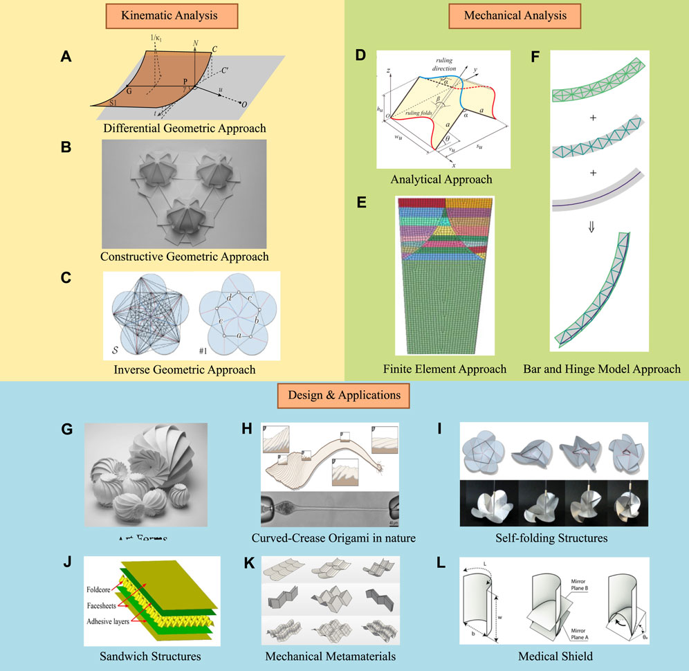
Figure 1. Illustration of the structure of this review on the curved-crease origami designs. (A–C) The kinematic analysis methods, which could be categorized by differential geometric approach [39], constructive geometric approach [40] and inverse geometric approach [41]. (D–F) The mechanical analysis methods, which could be categorized by the analytical method [42] where the energy of the crease is identified by obtaining analytical expression, the finite element method [43], and the bar and hinge methods [44]. (G–L) The designs and applications inspired by the curved-crease origami concept. (G) Beautiful art forms using the curved crease origami [45]. (H) The curved crease origami in nature, the single cell could reach high extendability through the curved crease origami design [46]. (I) The design of curved crease origami in the deployable structure where the folding motion is actuated by a thread and the self-interacted crease pattern [41]. (J) The sandwich structure based on the curved crease origami foldcore in the impact-resistant device [47]. (K) Design of the curved crease origami based on the Miura pattern, the “eggbox” pattern for mechanical metamaterials [48]. (F) Design of the shield structure for medical purposes inspired by curved crease origami [49].
Folding origami is always one of the hot spots in the eyes of mathematicians; even it could be used to solve mathematical problems such as constructing π and solving the partial differential equations [58, 59], another type of curved crease called “smooth fold” which considers the model for the non-zero thickness of the origami structures [60, 61]. However, this is not within the scope of this review. Here, we first detail the differential geometric approach using the concepts of the curvatures and the geodesic properties, as one of the major methods that are used in the curved-crease origami structure, and then several designs are reviewed.
Before we dig into the concept of curved-crease origami, first the concept of the curvature and folding of paper should be introduced. We briefly introduce the concepts that are crucial for understanding surface curvature in general and its relation to origami.
The principle curvatures of a given point on the surface, κ1 and κ2, are the maximum and minimum values of all the normal curvatures at that point, with the directions of corresponding curvatures denoting the principle directions [62], as shown in Figure 2. The principle curvatures and the direction normal describe how the surface curves in the vicinity of that given point, and on special occasions, when all these curves of intersection are of equal curvature (e.g., a point on a sphere or a plane), this is an umbilic point, and in this case, the principal directions cannot be uniquely defined. Except umbilic, the principle directions of other regular points are orthogonal. To quantitatively determine the curvatures, two measures are given: the Gaussian curvature K and the mean curvature H, as shown in Eq. (1) and Eq. (2).
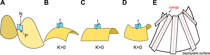
Figure 2. Illustrations of the principle curvature and the rulings. (A) At a given point P on the surface x, a plane that intersects of the surface x containing the normal vector N. When rotating about the normal vector at the given point P, infinite curves could be generated through the intersection of this plane with the surface x, and the maximum and the minimum curvature among the generated curves are defined as the principle curvature. (B–D) Illustrations of the surfaces with positive, zero and negative Gaussian curvatures [63]. (E) Demonstration of the rulings of a deployable surface: the tangent planes (in the shape of a “ruler”) along the rulings remain co-planar [64].
The Gaussian curvature was introduced in Gauss’s landmark paper, which is considered to be the most important theorem in differential geometry, and the names of points are determined as parabolic, elliptic, and hyperbolic when the Gaussian curvature is zero, positive, and negative, respectively. The mean curvature is an extrinsic measure of the surface that is dependent on the surroundings; on the contrary, the Gaussian curvature is an intrinsic property of the surface that shows the property of the surface and is independent of the surroundings [63].
The difference between these two types of curvature is important, as a surface could have a zero Gaussian curvature but a non-zero mean curvature, which shows that a surface could remain intrinsically flat while being intrinsically curved, i.e., bending flat paper and warping it into a cylindrical shape. Because of this property, the plane with zero Gaussian curvature is called a “deployable surface,” since a flat plane could be bent into a cylindrical or a cone shape without stretching, tearing and gluing, the cylinder or the cone are both deployable surfaces with zero Gaussian curvature. In other words, the Gaussian curvature, K, is a bending invariant; for every point on the surface x, there is a mapping that transforms a simple connected surface x to another simple connected surface y that preserves the Gaussian curvature. Surfaces that are related to this mapping that preserve the Gaussian curvature are called isometric, one could refer to the work of Paul [65] for a vivid visualisation. Callens et al. provided a comprehensive review of the curvature of the surface regarding origami structures [19]. So it is the same when one says that if a surface is locally isometric to the plane, it is a developable surface (one cannot stretch paper!). Such surfaces fall into the theory of Euler, where a developable surface is a ruled surface, as shown in Figure 2E, the ruled surface consists of a family of straight lines, which are called rulings. The rulings are tangent to the edge of regression. The rulings of a developable surface are the envelope of a family of tangent planes where all the tangent planes along the rulings of a developable surface coincide. One can put a ruler (as the tangent plane along the rulings) that envelopes a developable surface. In some cases, those rulings are also called generators.
Since the ruling is a straight line, a ruled surface is defined to describe how a point on the straight line travels in space; specifically, a ruled surface is a curved surface that is made by continuously changing the location of a point on the straight line in space by one parameter, as shown in Figure 3A. The point of the straight line with a unit directional vector of e(s) travels along the parametric curve P(s), so any position of the point X(s, t) on the straight line is expressed as a parameterized form, as shown in Eq. (3):
where t determines the position of the point on the straight line. Hence, t and s are two parameters that represent the parameterized form of a ruled surface. Note that not all the ruled surfaces could be made with paper, as shown in Figure 3B. Detailed qualitative properties of curved folding are shown in the work of Demaine et al. [66], Liu et al. [67] and Mundilova’s dissertation [68].
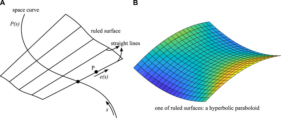
Figure 3. The illustration of the ruled surface. (A) A ruled surface is a curved surface made by changing the location of a point on a straight line s, the direction of the straight line e(s), so any position of the point X(s, t) on the straight line is expressed as a parameterized form of X(s, t) = P(s) + te(s). (B) The Gaussian curvature of the ruled surfaces could be non-zero, which indicates that not all ruled surfaces could be made by paper (i.e., not all ruled surfaces are developable).
The study of curved-crease origami usually starts with understanding the basic principle of folding a simple curved line on paper. One of the first and most influential analyses of curved crease origami structures was performed by Huffman, where the local folding behaviour is examined by using Gauss’ spherical representation [69]. The geometry of curve folding has been further studied by Duncan and Duncan [70] and Fuchs and Tabachnikov [64] using the differential geometric approach, where the concepts of geodesic curvature and geodesics are used.
Geodesic curvature belongs to the world of intrinsic geometry. Let us now consider a surface x with an in-plane curve ξ (the plane is in blue colour, as shown in Figures 4A, B, the curvature vector of the curve ξ at a given on-curve point P points from P to the centre of the curvature of ξ, therefore, this vector could be manually decomposed by projecting the curvature vector onto two orthogonal planes: the normal plane of the curve ξ at the given point P that contains the normal vector NP and the tangent plane of the curve ξ at the given point P, as shown in Figure 4B. The curvature of the projected curve on the normal plane denotes κn, while the geodesic curvature, denoted κg, equals the curvature of the projected curve ξ on the tangent plane at the given point. When the geodesic curvature is zero, there is no projection of the curve ξ onto the tangent plane, so the curvature of the curve ξ is identical to the normal curvature κn. A curve with geodesic curvature being zero everywhere is called a geodesic, and a geodesic connects two points on the surface with the shortest distance. Since the normal vectors along the geodesic curves now coincide with the normal vectors of the curves, there is an infinite number of geodesic curves passing through every given point on the surface (the readers are recommended to recall the process of deriving the principle curvatures where the intersecting curves could be generated by rotating the normal plane about the normal vectors, and those intersected curves are geodesic curves).
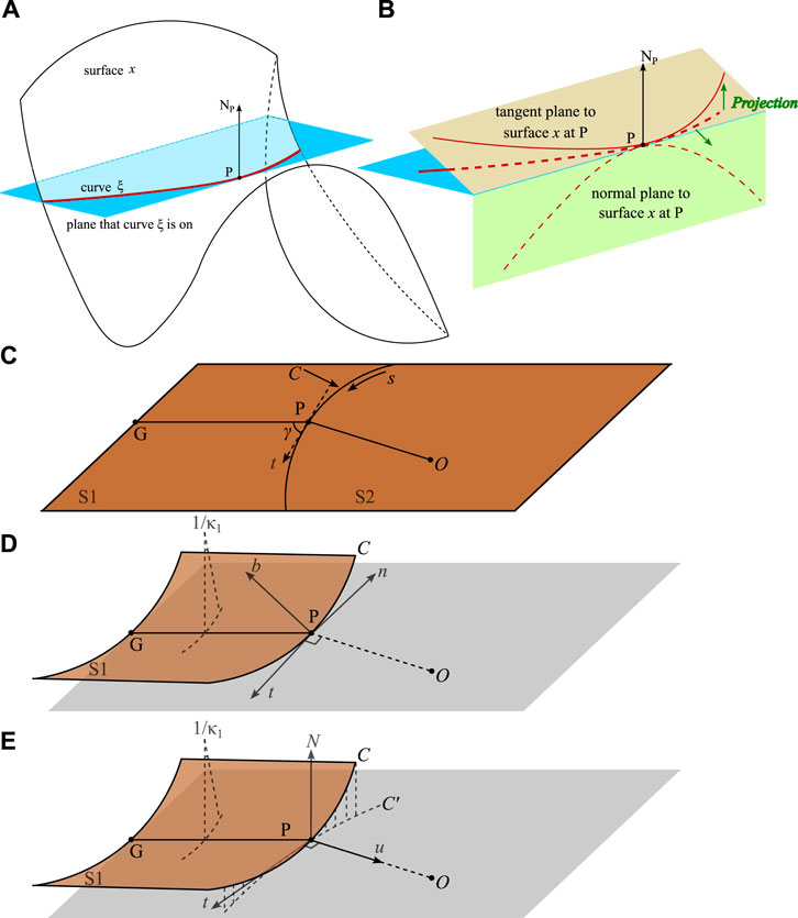
Figure 4. The geodesic curvature and the differential geometry of surfaces. (A) A curve ξ of surface x at a given point P with the normal vector of the given point denoted as NP. (B) The geodesic properties of the curve ξ of surface x at a given point P. The geodesic curvature, κg is the curvature of the projection of curve ξ on the tangent plane; the curvature of the projected curve on the normal plane denotes κn, the geodesic is the curve whose geodesic curvature of on-curve points are zero everywhere. (C,D) The illustration of a set of triple orthogonal vectors to express the space curve. (C) On the inextensible plane, the curve C divides the plane into S1 and S2 two regions, the straight line PG is the generator, the on-plane arc length of the curve denotes s, the tangent vector is t. (D) The surface S1 deforms about the generator PG, and becomes a developable surface, the unit tangent vector and the unit normal vector of the space curve C at the given point P denote t and n respectively. The unit binormal vector is derived by the cross product of the vectors u = t × n, thus forming moving triad vectors. (E) Another triad vector could be derived using the geodesic properties, the projection, C′, of the curve C on the tangent plane at P.
As the geodesic curves are definitely in-plane curves due to the definition, to describe a space curve, torsion is introduced here for measuring the bending of curves. A nonplanar space curve exhibits both curvature and torsion; the torsion of a curve describes the pitch and the degree of non-planarity of the curve. For a curve lying on a surface, it is general to use the geodesic torsion to measure the local bending of this curve, which complements the normal curvature κn and the geodesic curvature κg. The geodesic torsion of a given point at a given direction on a surface curve equals the torsion of the geodesic through that point in that direction. We could define a set of triple orthogonal vectors at a given point of the curve on the surface, the normal vector to the surface at the given point, n, the tangent vector to the surface at the given point, t, and the geodesic normal vector u (in some work, it is also known as the binormal vector and denoted as b) which is the crossed product of the n and t, u = t ×n. The changing rate of the normal vector n with respect to the arc length s projecting on the tangent vector equals the normal curvature, while the changing rate of the normal vector n with respect to the arc length s projecting on the vector u equals the geodesic torsion tg, hence, geodesic torsion complements both the normal and the geodesic curvatures, yet note that it does not belong to the world of intrinsic geometry.
Now, we will introduce the fundamentals of differential geometry of curved folds from the work of Ducan and Ducan [70]. As shown in Figures 4C, D, consider a curved crease line C on the deployable surface, it divides the surface into two sections, the line PG is the generator, and the left surface S1 bends along the generator. Now, the curve C becomes a space curve, at a given point P, the moving triad of vectors (the normal vector n, the tangent vector t and the binormal vector b) could be determined. The space curve C is determined by the principle curvatures κ(s) along the curve s and torsion τ(s) using the Serret-Frenet formula:
Note that this description is independent of any surface that contains the curve. However, with the assistance of a new set of triad vectors N, t and u in the tangent plane, the geodesic properties of the space curve could be described. As shown in Figure 4E, at the on-curve point P, the tangent plane is in grey colour, N is the unit normal vector of the tangent plane at the point P, the unit vector u is in the tangent plane and it is orthogonal to the unit tangent vector t. The projection of the space curve C at point P is C′, then, the curvature of the C′ on the tangent plane, by definition, is the geodesic curvature, κg of the surface curve, hence, the geodesic curvature vector denotes κgu, the normal curvature of the surface at point P is in the direction of the vector N, which is κN, the changing rate of the rotation of the normal vector N along the curve is the geodesic torsion denotes τg. The geodesic properties could be related using the Bonnet-Kovalevsky formulae, as shown in Eq. (5):
As shown in Figure 5, at a point P in any surface, the normal curvatures in two orthogonal directions, 0 and 1, corresponding to the maximum and the minimum values of principle curvatures, κ0 and κ1 exist, the geodesic torsions, by definition, are zero in these directions. For the other direction x with an angle of γ with respect to P0, the properties are given by Euler’s formulae as follows.
therefore, as the direction of y is orthogonal to the direction x (κ0 sin2γ + κ1 cos2γ), there are invariants from Eq. (6), as shown in Eq. (7):
where κmean and κGauss denote the mean curvature and the Gauss curvature respectively. As shown in Figure 5A, the surface S1 deforms about the generator PG and becomes a deployable surface (cylindrical shape), PG is a principle direction with the normal curvature κ0 = 0. In the tangent vector of t with an angle of γ to the direction of PG, the normal curvature and the geodesic torsion are found from Eq. (6), these could be further represented by a Mohr circle diagram (as shown in Figure 5C), the point T stands for the geodesic curvature κg and the normal curvature κN at the given point P in the tangential direction t.
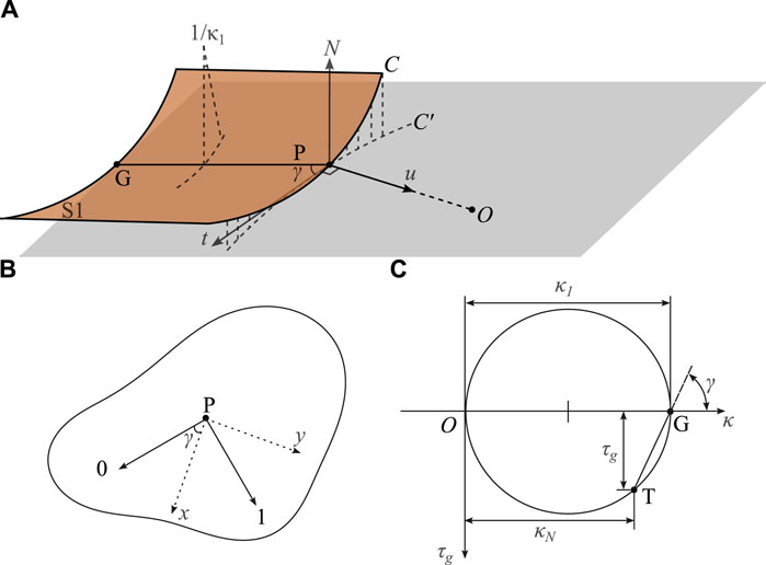
Figure 5. The geodesic properties and the Mohr’s diagram. (A) The surface S1 deforms about the generator PG and becomes a deployable surface (cylindrical shape), PG is a principle direction with the normal curvature κ0 = 0. (B) In the tangent vector of t with an angle of γ to the direction of PG, the normal curvature and the geodesic torsion could be further represented by a Mohr circle diagram in (C). (C) The Mohr circle diagram for the invariants formed by the curvatures on the surface at the given point in the given direction that is at an angle of γ to the principle direction PG, the point T stands for the geodesic curvature κg and the normal curvature κN at the given point P in the tangential direction t.
Three curvatures, the geodesic curvature κg (describes the tangent plane curvature, i.e., the planar layout of the fold curve), the normal curvature κN (describes the degree of out-planarity relating to the current surface curvature in a tangential direction to the geodesic curvature) and the curvature κ, are related in the Eq. (8) using Meusnier’s theorem.
this relates the curvatures to the fold angle 2ω, the torsion of the space curve τ, the changing rate of the fold angle with respect to the arc length dω/ds and the geodesic torsion τg using the theorem of Bonnet as follows (the proof is given in [70]), as shown in Eq. (9).
the relations are derived to form the compatibility conditions under the assumptions that, for the two surfaces S1 and S2 sectioned by the fold curve, at any shared point, the normal curvatures of the surfaces have the same magnitude but opposite sign; the changing rate of the folding angle with respect to the arc length on two surfaces has the same magnitude but opposite sign, as shown in Eqs (10) and (11), respectively.
Then, the relationship between the geodesic torsion and the changing rate of the fold angle with respect to the arc length is shown in Eq. (12).
Now, the normal curvature of the surface is obtained by the orientation angle between the tangent vector and the generator γ, and the principal curvature κ1 from Eq. (6), as shown in Eq. (13) and Eq. (14).
The fold angle of the on-curve points then forms the relationship between the curvature of the curve and the geodesic curvature κg, as shown in Eq. (15).
Here, it is explained how the curvature properties of a surface influence the folding process and the resulting shape, which is crucial for designing structures with specific mechanical properties. It is important to determine the distribution assumptions of the ruling lines on both sides of the crease, so the distribution of these virtual creases could physically satisfy the minimized energy condition of the surface.
By now, the derivations of the differential geometric approach to curved folding have been completed. When analysing the curved-crease origami, the given conditions are important. Two special degenerative cases were considered.
Case I: the folded curve remains planar after the folding;
Case II: the folding angle along the curve is the same.
These two conditions are exclusive to each other, which leads to the varying folding angles in Case I and the folded curve being a spatial curve (non-planarity) in Case II. The geodesic torsions of both surfaces τg,1 = −τg,2 in Case I and τg,1 = τg,2 in Case II. Since the tangential vector t is known, the generators on both sides of the curve are now determined through Mohr’s diagram. Note that it is exactly because the generators specify the developable geometries of both surfaces. As shown in Figures 6A, B, the folded curves and their corresponding generators. To conclude, folding along a curved crease satisfies the developability of the sheet, a curved-folded origami consists of developable surfaces (i.e., a cylinder, a cone, or a tangent developable to a space curve) sectioned by the curve crease.
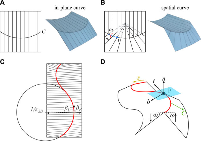
Figure 6. (A,B) Illustrations of folding an inextensible paper using (A) co-linear generators and (B) generators reflecting at the same angle. (C,D) Illustrations of curved folding in the matrix form of Eq. 4 given by Tachi [71]. (A) Case I: The folded curve is an in-plane curve. (B) Case II: The generators are equally inclined to the tangent, which is analogous to the light rays emanating from the centre of the source; the folding angle is the same everywhere on the curve, and the folded curve is a non-planar curve. (C) the crease pattern before folding. (D) The triad of a given point P on the curve C with the arc length s. The folding angles of both patches connected by the curve C are ω.
Several studies have extended the research on curved-crease origami using the differential approach. Demaine et al. developed basic tools for curved-crease origami in terms of the definitions and theorems in a mathematical way; specifically, the studies of definitions of rulings and smooth folding are comprehensively investigated, and they provided proof of five high-level properties in terms of the rule segments [72]. Tachi [71] used a discretized form to analyse the curved-crease origami structures; hence, the non-rigid curved-crease origami could be simulated like a rigid origami structure with at most one degree of freedom. The differential geometric equations are expressed in the form of a matrix, which facilitates the use of the differential geometric properties in the analysis of the mechanical behaviours in the later studies, as shown in Eq. (16), as shown in Figures 6C, D.
where the normal vector n, the tangent vector t and the binormal vector b are defined in the same way above, note that this is the matrix form of Eq. (4). Based on the above studies, Honda et al. [73, 74] provided proof that for a given pair consisting of a crease and crease pattern, there are four distinct non-congruent curved folding.
The differential geometric method above, which is a conventional approach, could be seen as Eulerian from the perspective of continuum mechanics. From the deformed configuration of the structures, one identifies kinematic relationships and constraints (i.e., the dihedral angles between adjacent tiles, the distance between vertices), and then derives the relationship between these objects [75]. This could be further described from the perspective of the Lagrangian, where the relationship between the crease pattern in the flat reference configuration and the deformed configuration is built in a dynamic case, the work of Liu and James [76] has developed this Lagrangian method in the curved tile origami.
The constructive geometric approach, as implied by the name, is designing the origami structures using the geometric properties of the folding from the crease pattern; this method is also called analysis. In analysis, the specific crease is designed first with certain constraints, and the shape is then analysed after folding the pattern. Several studies demonstrate various curved-crease origami designs by designing the curved-crease pattern, and these designs are mainly shown as a form of art [40, 77, 78]. Here, we briefly introduce the curved-crease design using a constructive geometric approach.
Ignoring any in-plane deformation of a flat sheet, the Gaussian curvature remains zero at each point regardless of arbitrary folding processes, ensuring that the resulting three-dimensional structure is developable. With this premise, we can skillfully design creases to realize our targeted three-dimensional shapes. Jun Mitani has introduced an innovative design approach that leverages a series of fundamental curved folding patterns [40], just as shown in Figure 7. By tessellating these basic units, a plethora of captivating three-dimensional forms can be crafted, showcasing the beauty and versatility of origami-inspired design.
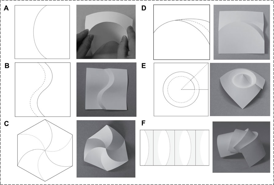
Figure 7. Illustrations of the basic curved folding pattern [40]. (A–F): single curve, aligning curves, aligning rotated curves, tucking, folding cones, and folding back at straight lines.
Mirror reflection is a traditional method to design the crease pattern of both the straight and the curved crease origami structures [79]. Here, a variety of research methodologies are demonstrated, as shown in Figure 8. The mirror reflection technique in the origami design does not alter the intrinsic curvature of the surface [71], so the differential equations for developable surfaces still hold when using the mirror reflection technique.
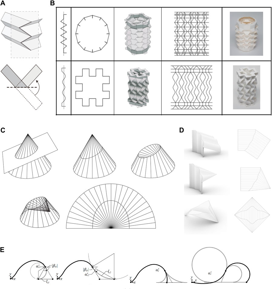
Figure 8. Illustrations of curved folding of developable surfaces. (A,B) mirror reflection technique and designs by Mitani [79]. (C) The use of the mirror reflection technique on a conic surface does not alter the intrinsic Gaussian curvature [71]. (D) A design method for all types of developable surfaces into cylinders and cones [82]; figures from the top to the bottom are the basic type of developable surface folded into a cylinder, a cone and an example of a generalisation of Huffman’s tessellation of the plane, respectively. (E) The “end arc addition rule” proposed by Gattas and You [83] for designing the curved-crease cladding. From the left to the right, the figures demonstrate the axis intersection with end arc addition of the smallest-radii end arcs and intermediate end arcs.
Another technique is to design the curved-crease origami by discretizing the non-rigid origami into a rigid origami. Tachi [80] showed the discretized method could be extended to tessellated, cylindrical, and cellular structures, as the condition of flat-foldability originating from constant-angle folding is satisfied. The non-twisting property of the deployable surface makes sure that the adjacent rulings could form a planar quadrangle. Thus, it is feasible to discretize a curved folded surface and approximate it with a planar-quadrilateral (PQ) mesh. Later on, Tachi [81] showed that when the curvature and torsion functions are given, a space curve could be defined, and this method could be used for the geometric construction of the tubular structure. The curved folded tube origami structure under the discretized method shows a single-DOF rigid folding motion.
Similarly, Zhang et al. [84] investigated the problem of discretizing the curved developable surfaces that satisfy the equivalent surface curvature change discretizations using the Gauss map (to investigate the normal curvature change of the curved surface). After the discretization, the adjacent surface normal vectors could be derived under developability constraint. The Gauss spherical curves of different developable surfaces are set up under the Gauss map. The whole process contains two steps. First, spatially curved surfaces are mapped to spherical curves. Each point on the spherical curve represents the normal direction of a ruling line on the curved surface. This leads to the curvature discretization of curved surface being transferred to the normal direction discretization of spherical curves. Second, the Gauss map is linked back to the normal curvature of the developable surfaces by the error analysis. These developable curved surfaces are discretized into planar patches to acquire the geometric properties of adjacent ruling lines, hence, the geometric properties and constraints of the curved folding such as fold angle, folding direction, folding shape, and foldability are derived. This method is applicable to analysing curved folding on any generic developable surface.
Gattas and You [83] proposed a new method for generating and parametrizing rigid-foldable, curved-crease geometries from Miura derivative prismatic base patterns. First, the ellipse is created, and then the curved crease is subdivided into straight-line segments. Through these two-step constructive geometric methods, a curved-crease Miura pattern could be generated based on the Miura-base pattern, and further, the curved-crease configurations of tapered Miura, Arc, Arc-Miura, and piecewise patterns are generated. Later on, Gattas [85] proposed a generative design method to specify a shape grammar (which comprises a shape and rules) for the assembly and interaction of geometric elements. The method to generate piecewise cylindrical surfaces based on curved-crease origami surfaces was presented, and the grammar utilises a parametric arc shape and end-tangent continuity condition for recursive shape addition and arc assembly. This “end arc addition rule” provides a design technique for the practical construction of curved-crease cladding.
Mundilova [82] investigated the smoothly deformed developable surfaces in a mathematical method, instead of using the traditional methods to form the approximations such as discretizing the surfaces or optimising for developability and isometry to a given patch, the proposed method could explicitly provide a smooth description of the obtained surfaces and their developments. Although the limitations are that it, unfortunately, cannot prevent surfaces from self-intersecting and crease curves from escaping to infinity, the proposed method gives simple formulas for the parametrization of crease curves. Using the properties of the geodesic and the ruled surface, design methods for all types of developable surfaces into cylinders and cones are provided.
Folding along the curved crease on the developable surface cannot change the intrinsic curvature of the surface. However, there are still two approaches identified that could alter the global intrinsic Gaussian curvature using the curved-crease origami technique: the curved-crease couplet [86] and folding along the concentric curve crease, which mostly could be categorized as the constructive geometric approach.
Curved-crease couplets were first proposed by Leong [86], which stands for combining pairs of curved and straight creases to create 3D origami with either positive or negative intrinsic Gaussian curvature that has been used by origami artists. Mitani proposed a design method and the software to generate the curved-crease pattern that could derive an origami structure with a rotational symmetric configuration [87]. Appropriate flaps are placed in between the polygonal faces to represent non-zero Gaussian curvature surfaces. The basic idea is to fold a flat sheet that could warp around the target object (a cylinder or a cone), and the extra parts are folded to form a flap, it is different from the design of Resch’s pattern, where the folds are hidden within the geometry [88]. A flap consists of a straight crease and a piecewise straight crease, which could be seen as a curved crease; hence, this forms a kind of curved-crease couplet. The proposed method mainly designs 3D origami structures with cylindrical and conical shapes. Later, Mitani proposed another method that could design 3D axisymmetric objects, the concept of “flap” evolved as the new feature of the method had 3D tucks with a triangular cross section [89].
Concentric pleating is folding the concentric shapes with the assignment of the mountain or valley of the crease pattern so that the geometries with negative Gaussian curvature are shown. This is the second technique that changes the global intrinsic curvature. As previously discussed, the flat sheet is a zero Gaussian curvature surface; hence, it cannot be folded into a non-zero Gaussian curvature surface. However, this could be realized when non-rigid folding is considered. By using the differential geometric constraints for the developable surface, Dias et al. showed that when the sheet is isometrically deformed everywhere except along the concentric fold itself, a relationship of constant curvature and oscillatory torsion is derived for a high stiffness of folds, whereas relatively softer folds result in oscillatory curvature and torsion with broken symmetry of the buckled shape [90]. Still, these works remain a field that is primarily reserved for artists.
The inverse approach, as opposed to the constructive geometric approach, is often a reversed design process, where the shape of the design is set up first, and the geometric constraints are used to determine the crease pattern and the generators. It is also called the synthesis. Mosely provided an inverse design method to solve the question of folding two developable surfaces from a single sheet of paper with a curved crease [91]. Since the developability constraint is too strong and there are only four types of developable surfaces that have been discussed, this limits the study to only a single crease through this analytical method.
Another type of design and analysis method that belongs to the inverse design category is the optimization method. By giving both initial and final configurations, Kilian [41] proposed a method that changes the problem from selecting the target actuation strings for the actuation of the self-folding curved-crease origami to complementary conditions. This method is similar to the ground structure method [92], the target configuration could be optimized and derived by a topology optimization. The challenge would be converting the research question to an optimization function and applying constraints. Still, this remains a promising future direction for analyzing more complicated curved-crease origami structures. Currently, much research focuses on inversely finding the straight crease pattern to achieve target functionality or configuration using data-driven methods [93]. The challenge is to provide a grid system for searching, and there is no universal analytical method for the curved-crease origami to conduct constructive geometric approach. The kinematic constraints of curved-crease origami largely depends on the properties of the curves themselves, which is object sensitive, (i.e., currently, one needs to define the geometries of the folded curves first, and then this mostly falls into the constructive geometric approach again). Inverse design methods for the curved-crease pattern remain unexplored. Hence this remains possible for future work on the inverse design of crease patternss that could be folded into the desired configurations.
Considering that many origami structures are tessellated to create periodic and repetitive geometric features, a ‘group orbit procedure’ has been proposed for the design of such specific structures [67], as shown in Figure 9. More specifically, origami structures are obtained by repeated application of an Euclidean group to an origami unit cell. One key of this process is that the element of an Euclidean group preserves isometries, and another is that the unit cells match with each other at creases.
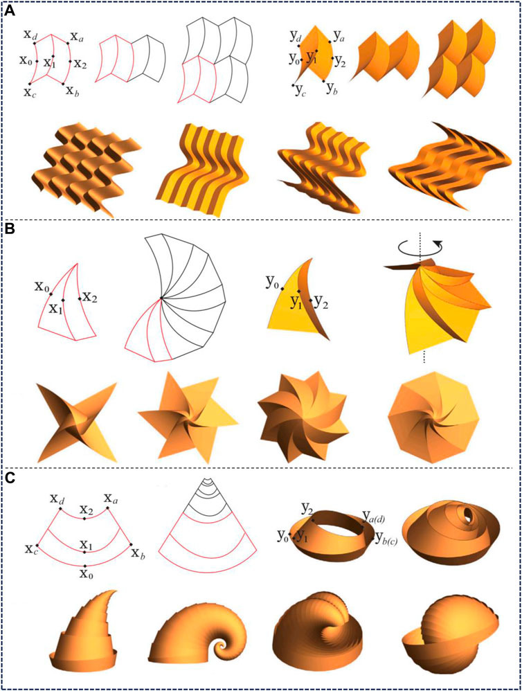
Figure 9. Three cases to show the design evolution process that starts from a single unit cell [67]. (A) Curved tile origami generated by translation groups. (B) Curved tile origami generated by circle groups. (C) Curved tile origami generated by conformal groups.
The foundation of group orbit procedure strats with an element of the group, which can be written as
where A ∈ O(3) represents rotation and
1. Selection of Unit Cell: Choose a reference unit cell containing internal creases, which will be acted upon by the elements of the group.
2. Application of Group Elements: Apply the group element a = (A|b) to the reference unit cell, generating the structure via a(Xi) = A(Xi) + b.
3. Ensuring Compatibility: Ensure that deformations at creases of adjacent unit cells are compatible, implying that boundaries of neighbouring unit cells match precisely after folding in both reference and deformed domains.
4. Structure Construction: Construct the entire structure through the iterative application of group actions. If the group is discrete, the structure will close perfectly without gaps.
For each group, detailed algorithms are provided, including locating reference creases, deformed creases, unit cell construction, and application of group operations. The introduction of conformal groups allows for the inclusion of scaling in the design, which is particularly useful for simulating growth patterns in nature (e.g., shells and horns). The design methodology with conformal groups is similar to helical and circle groups, but scaling factors need to be considered. Curved origami structures designed via the Group Orbit Procedure not only possess excellent geometric properties but can also have their stored energy calculated using Kirchhoff’s nonlinear plate theory, which is crucial for understanding the mechanical behaviour of the structures. It provides a powerful tool for designing complex curved origami structures, leveraging symmetry and repetitiveness to generate structures. Karami et al. [94] also adopted similar methods, primarily focusing on the application of curved creases in the Miura origami tessellation pattern, and extending the aforementioned construction method to curved creases α with arbitrary profile functions f.
The mechanical analysis of curved-crease origami focuses on studying origami structures from the perspective of a structural engineer, where the energy, the equilibrium of structure, the compatibility constraint of the fold, the bistability or multistability, the “snap-through” effect of the structure. It is certain that none of the questions above could fall beyond the scope of mathematics of the differential geometric approach in the previous section. Still, the intention here is to address the analysis method, the modelling technique and the formulation of the energy function, providing a reference for the future development of curved-crease origami in the field of engineering. Here, Figure 10 displays related research studies, mainly explaining a case study on the analytical methods for designing curved-crease origami structures.
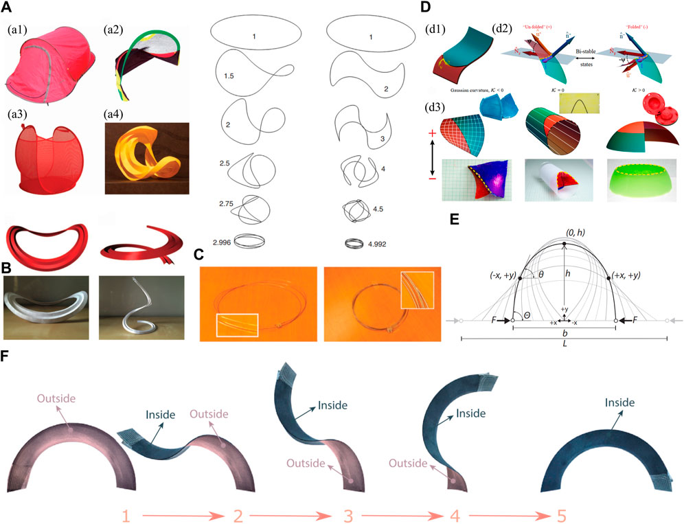
Figure 10. Illustrations of the case study of the analytical methods of designing curved-crease origami structures. (A) The overcurved shapes that could be found in daily life: (a1) Foldable tent, (a2) foldable football gate, (a3) foldable laundry basket and (a4) curved-crease origami art form [95]. (B) Two types of concentric pleated folds, the open one and the closed one, with a saddle-like and a helical shape, respectively [99]. (C) A demonstration of how to fold an overcurved structure [95], this work also highlights an interesting question that the overcurved ring is in an odd number. (D) Folding of curved shells along a crease, the “pop-through” effect of the curved facet could be understood by an osculation of the partial surface along the fold [100]. (E) The illustration of the “Elastica” curve, which is the elastically-deformed shape of a slender beam [55, 101]. (F) The illustration of an elastic neutral stable structure [98].
Due to the geometric complexity and the variety of the designs, researchers often use analytical methods to build their own models to describe the research question. Inspired by the ring-shape designs that are buckled or folded in tridimensional saddle shapes such as overstrained bicycle wheels, released bilayered microrings and strained cyclic macromolecules, Mouthuy et al. [95] proposed an analytical model using the minimization of the energy method of overcurved rings to capture the shape and buckling behaviour quantitatively. Here, the overcurvature O is defined by the contour length L and the curvature of the ring in the planar shape κ,
Regarding the energy method that applied in the compliant mechanism, there is another interesting topic intrigued by curved-crease origami or curve folding: elastic neutral stability. An elastic mechanism in neutral equilibrium is defined to only deform without load if the necessary energy for deformation is already stored in the system and redistributed upon reconfiguration [96]. This unique property was investigated by Guest et al. [97]. Since it requires the energetic state of the structure to remain unchanged during a deformation mode, the neutral stable mechanism features a continuous equilibrium as its behaviour resembles the fascinating class of statically balanced structures [98].
For certain specific structures, especially those with periodic or fractal characteristics in origami, it is possible to first obtain the deformation coordination relationship of the basic unit through discretization methods, and then derive the continuum equation for the entire structure. Dias et al. [99] developed recursion equations to describe the three-dimensional shape of concentric pleating, where folds have been inscribed. Using the differential geometric equations detailed in the previous section, the continuum equations (valid in the limit of vanishing spacing between folds) and the energy of the structures are derived, and the smooth surface intersecting all the mountain folds is described. Multiple folds are considered in their study, but the relationship between two consecutive folds needs to be predefined first. They explored the methods of designing the concentric pleated folds. Two types of folds are considered: closed concentric folds form a saddle-like configuration (which is also demonstrated in Section. 2.2) and open concentric folds result in helical shapes.
The bending facet during the folding of curved crease origami could trigger interesting effects such as the “snap-through” effect, where the facet could change its configuration swiftly during the deformation, or the “pop-through defect” [102, 103], where the local deformed vertex changes its equilibrated position and creates a self-locking effect or bistability of the fold. For thin materials, curvature and mechanics are intimately connected to each other. Inspired by the swift “snap-through” effect, Bende et al. [100] introduced the design rule to explain how to generate the snapping transitions on arbitrary surfaces. This design rule is independent of the material system and the length scale. When the curved surface is deformed to another position by a “pop-through” effect, it could be understood that the partial surface osculates along the fold (defined to have zero normal curvature κN) about a certain angle ψ, and the type of the curved surface is determined by the Gaussian curvature and further determines the curvature properties along the fold. Through the geodesic properties, the bending energy is derived using the mean curvature of the shell near the fold. The finite element method is used to validate the case study.
Similar to the discrete method, the Gauss map method is an efficient tool to analyze the shell damage mechanism and bistable creased strips [104, 105]. As shown in Figure 11, the normal vectors of a closed contour in the vicinity of a given point could be transformed into a unit sphere. The Miura-patterned origami in unfolded state, the planar configuration has zero Gaussian curvature, after the transformation, the overlapping unit normal vectors form a zero surface area, indicating zero Gaussian curvature. After folding the miura pattern, the unit normal vectors of 4 surfaces transform into the Gauss map, unit normal vectors trace out arcs of great circles on the unit spherical surface, with lengths equal to the relative dihedral angles between the facets across hinge lines (the length of C in Figure 11D equals the dihedral angle ϕ12 between S1 and S2, as the radius of the unit sphere r = 1), the enclosed surface is formed by two same-area surface, but following the sequence from n1–n4 forms a clockwise and a counter-clockwise surface in Figure 11D, which gives a net-zero surface, indicating that bending does not change the metric of the sheet, the Gaussian curvature will remain zero at (nearly) all points on the folded sheet [106]. The signed area enclosed by these arcs Γ′ is equal to the angular defect at the vertex, which measures the solid angle and, hence, the Gaussian curvature of the vertex P. The Gauss mapping technique involves generalising an arbitrary number of hinge lines, which become the generators of a developable surface as the number increases. It is capable of describing the kinematics of a hinge and facet model, which forms a discrete version of the bistable creased strip. Walker and Seffen [104] studied the creased strip problem. By discretizing the single vertex on the strip into several sectors and deriving the energy function of both regions separately through the analytical method, the energy function could be solved by getting the minimum energy and the net zero Gauss mapping constraint. Although the limitation of this work is that the discrete model that is based on the Gauss map only predicts the final shape of real sheets well for small deflections, large deflections are often observed in experiments [107]. Still, this creased strip with a hole structure with bistability could be used as part of a multistable structure for future applications.
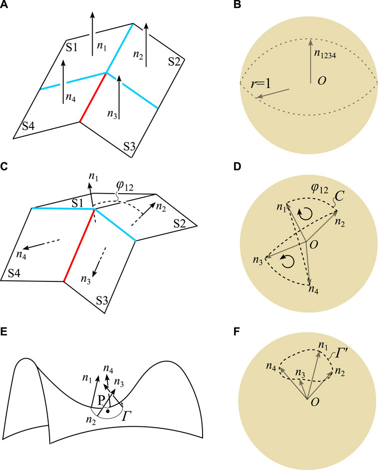
Figure 11. Demonstration of the Gauss mapping. (A) The Miura-patterned origami in an unfolded state, the planar configuration has zero Gaussian curvature. The normal vectors denote n1, n2, n3, and n4 of surfaces S1, S2, S3, and S4, respectively. All the normal vectors transform into the unit sphere, and the enclosed surface formed by a closed, oriented contour connecting the endpoints n1–n4 sequentially is the Gaussian curvature. (B) All the unit normal vectors are overlapping, so the enclosed surface is zero. (C) In the Miura-patterned origami in a folded state, after transforming the normal vectors to the unit sphere, the enclosed surface is (D) a net-zero area surface, indicating zero Gaussian curvature. (E) For a given point P, the enclosed area by Γ has a negative enclosed area after the transformation (as the curve Γ′ in (F) is in reverse direction), which indicates the negative Gaussian curvature.
As opposed to the discretized method, Lee et al. [55, 101] presented an analytical geometric construction method for curved-crease origami by combining a 1D elastica solution for large elastic bending deformation with a straight-crease origami projection and mirror reflection process; the proposed method could accurately capture the principal curvature and developability characteristics of the surfaces of the elastically-bent curved-crease origami. Also, by defining the conditions for the appearance of distortion (distortion will occur in the primary surface if secondary pattern creases are parallel to primary pattern rulings), the multistate origami, defined as the structure that could achieve multiple design configurations or objects, could be designed [108]. Elastica curves are the elastically-deformed shapes of a straight, slender beam; therefore, the analytical solution of the “elastica” curve could be derived; however, when used as the curved-crease of the origami, the curved-crease unit cell constructed would have a surface with non-zero Gaussian curvature. Still, this construction technique can generate an equilibrated minimum-energy surface [55]. The compliant folding behaviour of an “elastica” curved-crease origami metamaterial is studied in Ref. [109]. When using the “elastica” curve to build the curved-crease origami metamaterials by tessellating a single unit cell, due to the definition of the curve, it could not be differential at the shared node of two adjacent curves. Since the analytical solution of the “elastica” curve could be derived, the energy function could be generated through methods detailed in Refs. [110, 111]. For a given in-plane curve, such as the case of “elastica,” with the analytical expression f = y(x), the curvature of the in-plane curve could be given by structural mechanics, as shown in Eq. (18).
where y′(x) and y″(x) are the first and second derivatives of the curve function, respectively, with moment and flexural rigidity values denoting M and EI [55]. Then, the energy function could be written as Eq. (19):
where s is the arc length of the curve, and κ and κ′ are the curvatures before and after the deformation at the given point along the curve. The elastica surface generation method in a later experimental and manufacturing study can be concluded to be an effective surface design method to specify the actual shape of an elastically-deformed curved-crease surface [112]. Using a similar method to calculate the energy of the curved-crease origami and the geodesic property that the curve remains in-plane if the folding angle at any given on-curve point is the same, various researchers derive the energy of the structure by deriving the analytical form of the in-plane (after deformation) curve and integration. Sun et al. [42] provide the analytical form of the energy of the curved-crease origami metamaterials. Du et al. [113] proposed analytical models based on differential and integral methods for predicting the compressive stiffness and strength of curved-crease origami foldcores made of composite material, and a three-dimensional failure mechanism map was constructed, where the buckling theory of cylindrically curved plates will be used to estimate the critical stress. This study shows that the dominant failure mode of the curved-crease origami foldcores changed from buckling to crushing under the compressive loading condition. Note that the analytical form of the sandwich structure with curved-crease foldcore is first derived.
In practice, many applications are constrained to situations in which origami structures are made from assemblies of flat, rigid plates connected by hingelike creases. In such situations, the geometric configurations and the kinematics are fully determined by the crease network, while the structural response is a result of the crease network and the crease mechanics. By contrast, when considering the elastic response of the plates (i.e., bending, stretching, and twisting), a variety of new behaviours may emerge. In this case, the elastic response of the structure is determined by the competition between the flexural stiffness of the panels and the torsional stiffness of the creases. This raises interest in studying the mechanical properties of origami structures, the frustrated shaping [114], where the effective curvature of the deployed origami structures in equilibrium could be reached by a crease pattern, and the effects of crease stiffness and sheet thickness on mechanical behaviour [115].
With the development of the computer, a large portion of work could be solved using computer-aided software. Mierunalan [39] revisited the work of Duncan and Duncan [70] and proposed a non-linear geometric elastic numerical model to predict the shape of curved crease origami with complex extended curved crease networks. By understanding the key features of curved creases through differential geometry and experiments, the proposed method is capable of capturing hinge-like crease mechanics without applying the complex plastic material model. The finite element methods with two modelling techniques in ABAQUS were investigated and compared, as shown in Figure 12. The first one is the connector hinge method, where the crease is singular and the 2-noded 3D connector element (CONN3D2) is used for each pair of nodes on the corresponding creases, which simulates the mechanical behaviour of the rotation of the crease, and the *COUPLING constraint is applied. The second approach is the thermal approach (which is also used in an earlier Ref. [107]), where the crease is considered non-singular and two options are possible. (c1): The plate is divided into three parts: two plates and the crease region in between. The width of the narrow slice of the crease region w is twice the plate thickness t, as informed by [116]. A thermal gradient, ΔT, is applied through the thickness of the plate. Only the crease region is allowed to expand by specifying a linear expansion coefficient and zero expansion coefficient elsewhere; and (c2) instead of a region, the crease is simulated through a line, and the temperature gradient ΔT is applied through the thickness of the plate along a set of nodes along the crease line, with the finite width of the crease accounted for by ABAQUS by default. The mesh size of the elements, though required fine-tuning, approximates the thickness of the plate, t, as shown in Figure 12.
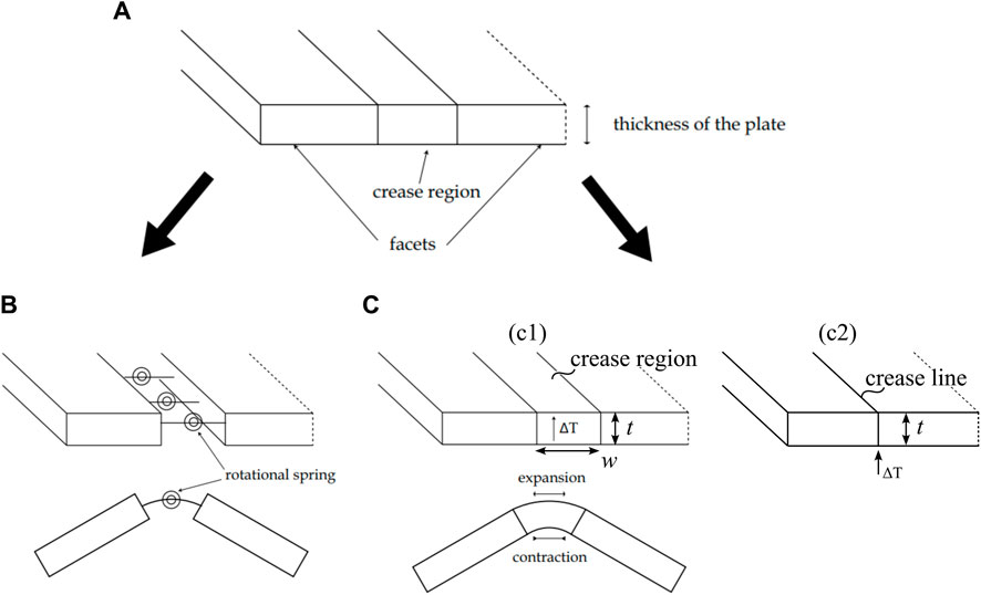
Figure 12. Illustrations of the modelling techniques using the finite element software ABAQUS [39]. (A) The reference configuration. (B) In the connector hinge method; the crease is simulated using the two-noded 3D connector element (Type: CONN3D2) of Join + Rotate type, with the *COUPLING constraint applied. (C) Thermal gradient method: (c1) The plate is divided into two plates and the crease region in between, the thermal gradient ∆T is applied through the thickness of the plate. (c2) Instead of a region, the crease is simulated through a line, and the temperature gradient ∆T is applied through the thickness of the plate along a set of nodes along the crease line.
For finite element (FE) numerical modelling techniques, each method has its own functional advantages and disadvantages [39]. Under the condition of a non-closed curved folding, the connector hinge was more computationally efficient; under the condition of a closed loop curved folding, the temperature method showed more efficiency in modelling. Therefore, the modelling techniques should be considered when using them to model curved creases. Still, the cases that have been studied were all quite simple. When it comes to a more complex model, the comparison of the advantages of different modelling techniques could still remain unknown, as the contact and interaction conditions need to be considered.
Hu et al. [117] proposed an FE model through 3-node triangles and 4-node quadrilaterals with translation degrees of freedom considered only. Since the bending deformation could be considered in the T3 model, a corotational constraint is applied in Q4 to quantify the bending deformation. The proposed methods of quantifying the bending deformation in Q4 and the derivative of the fold angle are implemented in commercial software ABAQUS using two user-defined element subroutines. Together with the built-in 3D membrane elements, they realize the simulation and analysis of origami in an FE environment. It is worth noticing that the code for the subroutines is kindly provided in their work.
The finite element (FE) method has been used in much research to provide validation of the model [118]. Thai et al. [43] developed the FE method through LS-DYNA and applied this to simulate the robotic folding process. The methods are quite similar to the connector hinge model. Most methods fall into the range of the three modelling techniques mentioned above.
The origami structure always has a special link to the bar and hinge model, as the bar and hinge model provides a relatively simplified version of how a 2D shell member mechanically behaves by only using the 1D member. Schenk and Guest [119] first proposed the use of the bar and hinge model to simulate origami structures, and over the years, there have been several derivative methods that are related to the bar and hinge model, such as compliant crease bar and hinge model and particle bar and hinge model [53], which makes origami structures share similarity with tensegrity structures as deployable structures [92], where tessellated tensegrity structures might have an origami dual. Figure 13 illustrates the process of constructing the bar and hinge model, from the basic unit to the discretization of the entire curved surface structure. The basic idea is to change the bending deformation behaviour and the in-plane behaviour of the facet to the axial elongation and the rotational mechanical behaviour of the bar and the hinge, so the energy at the system level could remain equivalent. The use of the bar and hinge model not only gives a simplified model to simulate the complex facet behaviour but also provides an analysis method for studying the “pop-through” effect or topology optimization [120]. In this section, we briefly review the bar and hinge model for analysing the curved-crease origami structures.
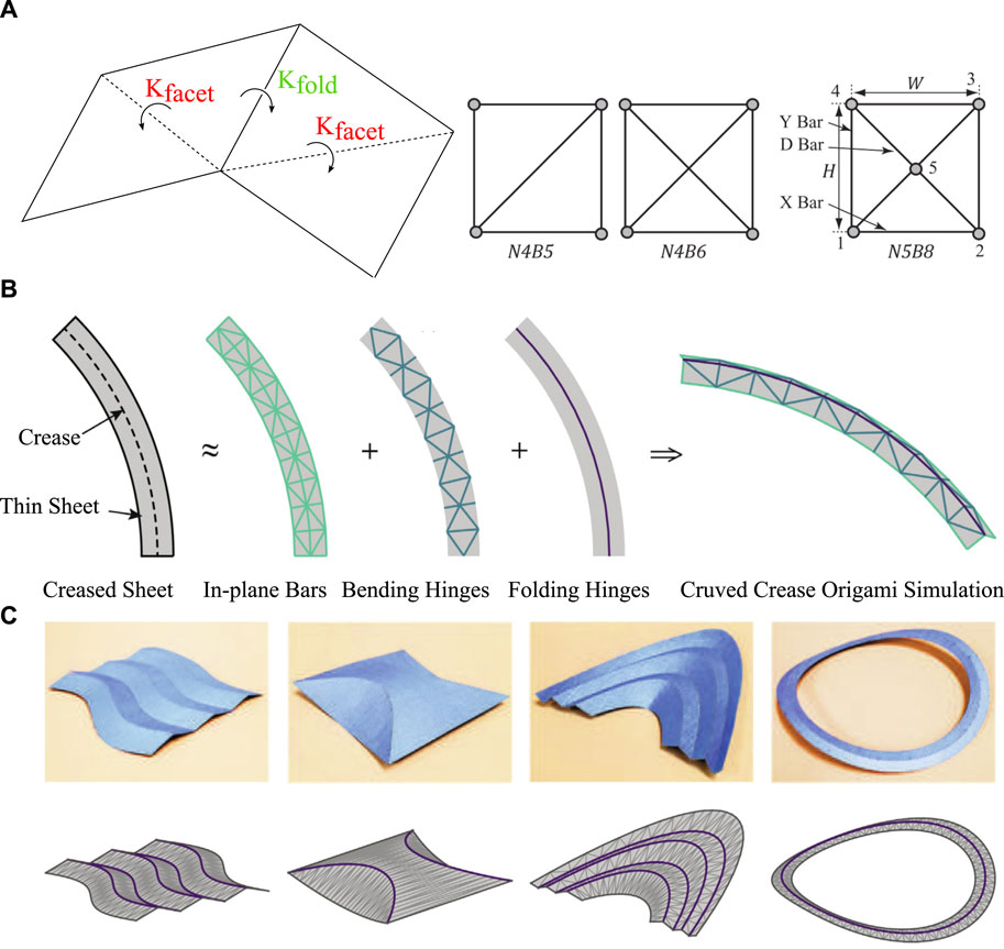
Figure 13. Illustrations of the case study of the bar and hinge model of designing origami structures by [121]. For simulating the curved-crease origami, one could discretize the curved line into piecewise straight lines. (A) Illustration of the basic idea of the bar and hinge model, the facet is triangulated, and a diagonal rotational hinge member is placed to simulate the bending deformation of the facet, and the folding motion along the crease is also replaced by a rotational hinge. (B) The bar and hinge method works by representing a creased, thin sheet using 3 elements: in-plane bars, bending hinges, and folding hinges. (C) The top row shows four photographs of paper, curved-crease origami constructed using a laser cutter and hand folding, and the bottom row shows the corresponding bar and hinge representations.
Zhang et al. [121] proposed a method that can control the folding path with the nodal coordinate; instead of analyzing the model based on the fold angle, the model based on the nodal coordinate is derived. The deforming path is obtained using an algorithm based on the generalized inverse theory, hence, it provides a kinematic analysis method for the folding mechanism of origami. Although this method is similar to the bar and hinge model, instead of the hinge member, the model is only modelled in terms of the bar member. Still, it could provide the reference for the folding motion of the origami structure, and the simulation method for the curved-crease origami is to model it in a way that is similar to the discretized method, the curved-crease becomes several connected piecewise straight lines.
Based on the initial “Node 4 Bar 5 (N4B5)” bar and hinge model, this method has been developed over the years by various researchers. Filipov et al. proposed an upgraded N5B8 model to simulate the model in a more accurate manner; Woodruff and Filipov [122] extended the model and applied it to the curved-crease origami in a similar way to the discretized method, the bars are grouped by their functionalities into the in-plane bar, the bending hinge, and the folding hinge, with the details of the numerical modelling technique providing in Ref. [123], and the experiments carried out to validate the model in Ref [44, 124]. Wo and Filipov [125] studied the multi-stability of the Kresling-based origami using the bar and hinge model. The method to convert bar members to shell members, so that the stiffness and the energy of the system are the same, is proposed. What is also interesting is that there is another stable state through the “pop-up” of the valley creases. Chen et al. [126] investigated the multi-stability of the hexagonal origami hypar by combining a group-theoretic approach through the bar and hinge model.
In a similar manner to the discretized method, the Virtual Crease Method (VCM) [127] is proposed to add virtual creases to simulate the large-bending deformation, yet the reason that this method is not catogrized in the constructive geometric approach in Section. 2.2 is that the derivation of the rotational stiffness of the real crease and the virtual crease could provide a reference for the bar and hinge method: the rotational stiffness of the real creases is obtained by conducting an experiment on a creased shell under compression, and the rotational stiffness of the virtual crease is derived to be proportional to bending stiffness per width under the assumption that the shell deforms into an arc with a uniform radius of curvature, and so the bending strain is constant throughout the entire shell.
Essentially, the energy in the bar and hinge model is derived from the elongation of the bar, the bending deformation of the hinge and the folding motion along the creases. Hence, the energy expression of the bar and hinge model could therefore be written as:
where
The core idea of the mechanical approach is to discretize continuous structures based on kinematic relationships and then to make reasonable assumptions about the deformation of the discretized elements (such as bars and hinges or shell elements), thereby determining the elastic potential energy of the entire system. The displacement field is then determined through the principle of minimum energy. In this sense, both the finite element method and the bar and hinge model actually follow this philosophy. However, for curved origami, each has its own limitations. The FE model makes it hard to predict the kinematics of the whole origami structures due to the complicated boundary condition and the coupling effects of the facet bending and the hinge rotation, making the analysis difficult to converge. Although the bar and hinge model could provide a computationally efficient method compared to models whose models use 2D shell elements, one major challenge would be how to effectively describe the mechanical behaviour of a 2D shell member to the combination of several bar and hinge members in an equivalent manner, i.e., there will always be room for error when one tries to spread forces across a triangular panel into one bar. Determining the equivalent stiffness of the bar and hinge model remains the challenge. Besides the experimental method to derive the rotational stiffness of the crease line by Wang et al. [127], Feng et al. [128] derived the equivalent stiffness of the crease using the elastic/plastic plate theory. Nevertheless, this still provides a promising analytical tool for curved-crease origami, especially when the complexity of the structure is upgraded to the system level and when the stiffness matrix and the mechanism of the structure are of interest for investigation.
In the colourful world of origami structures, origami has been applied in various fields due to its versatility in the aspects of geometry, pattern, material, and mechanisms [129, 130]. Chen et al. reviewed the origami design methods and mentioned the kinematics and bifurcation behaviour of the origami structures, but only the straight-crease origami structures were reviewed. The development of the curved-crease origami structures is still underexplored [131]. Over the years, curved-crease origami structures have been applied in many fields. In this section, the applications and the design of the curved-crease origami are discussed.
Miyashita et al. [132] designed self-folding layered materials based on complex three-dimensional curved-crease structures, and the manufacturing process and the actuation methods are investigated. By changing the curvature of creases to regulate the folding angles, design and modelling techniques are derived and applied to fabricating propeller blades. The research questions of self-folding are demonstrated in this work: (1) predict the folding angle of a curved crease accurately; (2) avoid the self-locking and achieve a final functional structure after the self-folding process of curved creases; (3) a method to actuate the device after it has been self-folded to demonstrate functionality. Since self-folding is a technique that was recently developed to aim at the rapid manufacture of structures by the folding of many small and complex creases, the application of self-folding here showed promising potential for curved-crease origami applied to mini-robots and actuation devices, as the successful triggering of one active curved crease could actuate the adjacent facets due to the coupling effect from the facet bending. Other self-folding methods include drawing black ink lines as actuating hinges on the shape memory polymer [133]. Tahouni et al. [134] presented a material programming approach based on self-shaping curved folding to create curved crease origami structures that could self-assemble from flat into a 3D folded state under actuation. The digital 3D-printing fabrication process using shape-changing materials and a computational design workflow for the geometric crease pattern are proposed.
Deng et al. [135] utilised the system-level stretchability of the origami folding to design the curved display in electronics. They demonstrated the design and fabrication of curved displays by optimizing 2D origami patterns for target 3D shapes using origami tessellation. The bending energy in facets is minimized using the optimization algorithm. The finite element method was employed to design 2D origami tessellations for the desired surface topography. Origami-based curved displays for typical nondevelopable surfaces (i.e., spherical and hyperbolic paraboloids) are manufactured. The pre-folding in origami structures acts as a geometric imperfection, which reduces the initial buckling force and increases the average overall reaction force. The origami derivative structure has much-improved energy absorption characteristics [136], enhanced buckling propagation capacity [137], and the ability to predetermine buckling mode [54] than traditional tubes; hence, they show great potential in energy-absorption devices and pipelines. Vergauwen et al. [118] proposed a method for the design and fabrication of pliable structures based on curved-line folding; the work provided a detailed finite element modelling method. They demonstrated the factors that could affect the fabrication of the physical model, and they have identified that the translation of the curved crease into a smooth working flexure hinge remains one of the big challenges. Nelson et al. [138] proposed an origami-inspired sacrificial joint through the compliant mechanism; although it utilises rigid origami, it opens up the possibility for curved-crease origami, as curved-crease origami could offer a more versatile design space to create regions of high and low stiffness and the proper alignment of compliant flexures in folded mechanisms.
When the curved-crease origami is applied to the sandwich structure or metamaterials, the shape of the curved crease enables smoothness and continuity in one direction, making them potential energy absorption devices. Xiang et al. [139] reviewed the energy absorption ability of the origami-inspired structure and material, which gives a clear connection between the energy absorption capacity and the geometry and material of the origami structures. They also point out the importance of understanding the behaviour of the folds and their relationship with the failure modes; other future avenues could be the limited research on the dynamic properties of the origami structure, the design of graded origami structures, and the limited understanding of the energy absorption capacity of the bio-mimic origami structure inspired by nature, such as an insect’s wing, leaves, and durian shell. Deng et al. [47] studied the low-velocity impact behaviour of the composite sandwich structure with curved-crease origami foldcore, and showed that they have better performance numerically and experimentally. The origami-based foldcore is designed not only for planar sandwich structures but it could also be designed in a cylindrical shape, with the constraints of foldability and developability of the curved-crease foldcore being considered [140].
The versatility of the design space and the capability of manipulating the stiffness of curved-crease origami make it achievable for various functionalities such as tuning motion, saving energy, and delivering high power, as shown in Figure 14. Zhai et al. [141] designed a curved-crease origami to accomplish in situ stiffness manipulation covering positive, zero, and negative stiffness by activating predefined creases. The method is similar to curve-folding of cylindrical surfaces and has been used for applications such as grippers, tunable stiffness cubes and multistage robots. Furthermore, curved-crease origami structures have shown significant potential in improving and optimizing the mechanical performance of materials. A carbon fibre-reinforced composite foldcore based on curved-crease origami reduces the abrupt changes in the fibre direction, hence avoiding the wrinkle of the fibre composite material, as opposed to the straight-crease counterpart. The adoption of curved creases enables smoother guidance of structural deformation and buckling [113]. By designing pre-embedded creases, the process of compression and buckling in energy-absorbing tubes can be controlled. The buckled shapes can be precisely described as an elastica minimum bending energy surface [54]. These applications demonstrate the advantages of utilizing curved origami in the design of metamaterials and meta-structures. Compared to straight creases, curved creases offer a larger design space and richer mechanical performance, providing a more diverse range of potential applications for future engineering scenarios. In recent studies, the kinematics and actuation of intrinsically curved folds (ICFs) have also been found to gain potential for designing developable structures [142]. The elementary way to form intrinsically curved folds is to stitch together along the curved boundaries of two flat sheets, as shown in Figure 14E. Unlike origami folds, the curved fold is not bending isometric of flat sheets, combining different curvatures (positive or negative) of the curved boundary features interesting behaviours, the essential kinematic feature of ICFs is that fold angle dictates curvature and vice-versa. Thus, the bending mechanism of the symmetric positive fold trading curvature could form simple mechanisms where a small actuator controlling the fold angle could be used to manipulate the fold’s curvature.
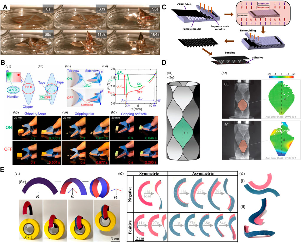
Figure 14. Structural design and applications (A) The self-folding propeller design by Ref. [132]. (B) Gripper design by Zhai et al. [141], the coupling effect of the folding and the facet bending enables fast actuation. (C,D): The curved-creased origami designs enable smoother guidance of structural deformation and buckling, and avoid the kink at the intersecting point of the creases, this is especially the case for structures that are made from fibre-reinforced composites. (C) The sandwich foldcore design inspired by curved-crease origami [113]. (D) Foldable energy-absorbing tubular structures using pre-embedded curved-crease origami patterns [54]. (E) The study of the kinematic features of combining different curvatures of intrinsically curved folds (ICFs) [142]. (e1): Bending mechanism of the symmetric positive fold trading curvature vs. fold angle and the simple mechanism is used for a corresponding paper grabber design. (e2): Experimental tensile strength measurements for the different types of folds with either positive or negative curvatures of the curves at the boundaries. (e3): (i) Paper model that is formed by stitching 2 strips with asymmetric geodesic curvatures κg and (ii) the resulting ICF has a curved ridge with non-zero torsion.
There are studies that are not limited to the numerical design method and focus on the practical techniques related to curved-crease origami. Cui et al. [112] investigated the manufacturing method of the curved crease origami beam structure. Sargent et al. [143] examined the processing methods of PET material sheets on the crease properties of origami mechanisms; they found the stiffness could be altered by the heat processing, and the temperature of processing was the primary factor in determining the force response. Other applications could be found in arc footbridge [144], metallic column [145].
The applications listed above primarily focus on robotics, aerospace engineering, and flexible electronics. Due to the design flexibility of origami structures, there is already a significant amount of research on origami and curved origami in these fields. Here, a broader perspective is provided to explore the potential applications for interdisciplinary of curved crease origami, as shown in Figure 15. For instance, the mathematical and mechanical principles of curved creases can be applied to DNA helices. Franquelim et al. [146] demonstrate the design of various DNA origami structures to simulate the three-dimensional characteristics of the BAR protein family and investigate these structures’ abilities in membrane shaping and transformation. Xie et al. [147] explore the adjustment of the bending and twisting properties of DNA origami structures through mechanical design and chemical modifications. In the field of architectural design, large-scale variable structures present promising development prospects for future urban construction. Some studies [148] have already employed discretization methods to design surface parameters for these structures. In medical device design, curved origami structures can serve as an entry point for designing microstructures, such as in heart stents [149]. Compared to straight creases, curved origami structures offer a more rounded design, reducing vascular damage and enabling faster self-folding responses, thus exhibiting better deformation performance. In the field of biomimetics, inspired by origami structures, researchers have conducted design and research on insect wing structures. Houette et al. [150] modelled an approximate curved surface of insect wings based on the Miura-ori pattern and explored how a single vein actuator could deploy this surface. Mintchev et al. [151] designed a novel origami structure with dual stiffness characteristics, composed of pre-stretched elastic membranes (similar to the soft resilin joints in insect wings) and rigid tiles (similar to the hard cuticle in insect wings).
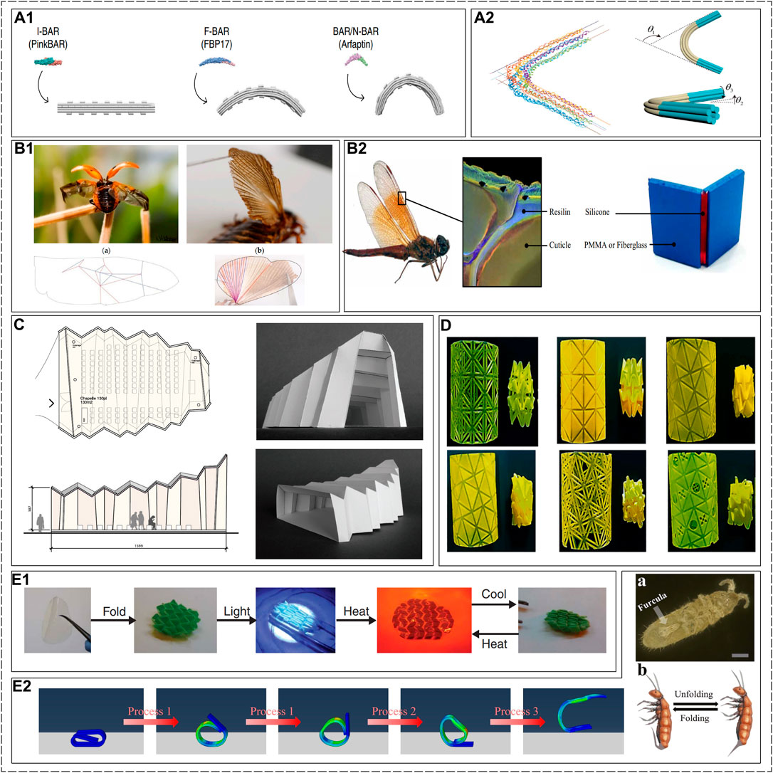
Figure 15. Applications of cross-disciplinary. (A1) DNA origami structures that simulate the BAR protein, which can be seen as curved creases [146]. (A2) The bending and twisting behaviour of DNA origami structure [147]. (B1) Approximate curved surface of insect wings based on the Miura-ori pattern [150]. (B2) Pictures of a Brachythemis contaminata and of its hindwing nodus. Blue and Red indicate resilin and cuticle [151]. (C) Origami Structure that models an architecture [148]. (D) Heart stents based on the origami waterbomb pattern [149]. (E1) A structure of LCEs based on the Miura-ori pattern, which can deform through light exposure and thermal stimulation [152]. (E2) Jumping actuator based on a three-leaf panel fold structure [153].
Another potential application is LCEs (Liquid Crystal Elastomers). LCEs are promising soft matter-based active materials due to their two-way shape-memory capability, fast and large-amplitude shape morphing, and intrinsic programmable liquid crystal (LC) mesogenic alignment [152]. They combine the orderliness of liquid crystals with the reversible deformation capability of elastomers. The liquid crystal moieties in this material can form an ordered arrangement under specific conditions (such as temperature, solvents, etc.), endowing the material with anisotropic properties. By cleverly positioning the triggers, controllable folding patterns can be imparted to the material. There have already been some related studies: McBride et al. [153] developed a developable Miura-fold actuator that unfolds and retracts through heating or light stimulation; Hu et al. [154] designed a jumping actuator based on a three-leaf panel fold structure. However, studies of LCEs combined with curved crease origami are still unexplored. In fact, due to the deformation of curved crease origami being a coupling of facet bending and crease buckling, this more complex deformation mode, combined with the controllable deformation capability of LCEs, will greatly expand the design space for potential soft robots, intelligent mechanisms, and smart materials.
This paper reviews the analysis methods of curved-crease origami (i.e., the kinematic and mechanical analysis methods), the corresponding applications, and the design. The basic principle to describe the curved crease is detailed in the differential geometric approach analysis section; these become the fundamental kinematic tools for the analysis of origami structure along the creases, whereas the inverse geometric approach is reviewed to find the curved crease that could achieve the target function of the final design. The mechanical analysis methods are divided into three aspects: the analytical method, the finite element method, and the bar and hinge model method, with each of the methods being critically discussed. Finally, the design and applications inspired by the curved-crease origami are shown. The essence of curved-crease origami ensures that there is always a combination of the effects of facet bending and the rotational stiffness of creases. The origami structures are investigated, whether in a discretized way, so the model could degenerate to the rigid origami, or in the bar and hinge model, so the kinematics or mechanism of the origami structures could be derived. Here, we offer several key themes for future challenges from our perspective.
Approximating intrinsically curved surfaces with the prescribed fold and cut curved-crease patterns directly corresponds to the final 3D shape, and no additional deformation is required after folding. The conventional method for straight-crease origami is to design the origami tessellations in their unfolded states and then deploy them to the 3D configurations that fit the intrinsically curved surfaces. Since there are infinite solutions for the curved crease line that connects two vertices, designing curved crease origami that could fit the complex configuration remains a challenge. The inverse design method, as one of the potential methods that could solve the problem, remains unexplored. Future applications could be the design of sandwich structures that approximate the complex shape of panels [155], searching the crease pattern of the curved-crease origami using the additive algorithm [156]. A recent study [142] has also pointed out the future directions for intrinsically curved folds (ICFs) to trace an arbitrary 3D space curve in its equilibrium state or the ICF-inspired morphing structures that enable transformation between multiple space curves through angular actuators along its length, which is also the results from the fascinating coupling effects from the crease folding and facet bending.
Despite many recent developments in deployable structures, the folding sequence and control over the folding creases make self-folding a challenging task. This is especially the case for the curved-crease origami [133]. Folding a single crease could lead to the bending deformation of the curved facet, which might further trigger the actuation or the “snap-through” effect of the adjacent facet. This intrinsic complexity, as one of the inherent natures of non-rigid origami, might require a larger force to actuate the hinge rotation. One could ask whether there is a triggering actuation mechanism that could lead to a “chain-reaction” effect of the actuation of the curved facets. Further, the actuation sequence or changing the definition of mountain/valley crease could lead to the self-locking state of curved-crease origami. With most of the work investigating straight-crease origami, using sequential self-folding to include self-locking mechanisms based on curved-crease origami could be highlighted as a potential future direction [157, 158]. Recent work has been focused on the actuation method using light [133], string [41] or heat-sensitive self-folding technique [132]. The main technique is to design the method to actuate the crease of the origami structures. Those studies also highlight one interesting future direction of “staged folding sequences,” i.e., the flat surface can be physically actuated by cycling through a set of predefined “keyframe” surfaces. Another interesting future work would be increasing control accuracy and versatility, where the individual string could be controlled through multiple actuation.
One recent study has identified two folding motion paths between unfolded and folded states [76]. Although comparing the paths does not fall within the scope of that research, the question arises: how many motion paths could be formed between the initial reference unfolded configuration and the final folded configuration? Is there a method that could form the multistable curved-crease origami by applying the rotational hinge to the structure so that the energy landscape is altered, similar to the method in Ref. [159]?
Most of the analysis methods for curved-crease origami structures are based on differential geometric design, yet there is a lack of a general method that could be used for curved-crease origami. Currently, there are Eulerian and Lagrangian methods, where both methods are based on the differential geometric approach. The former method is used in the small domain, whereas the latter method shows potential to be used in the large domain with certain restrictions [76]. However, these methods use isometric mapping as the necessary condition to derive the relationship between the deformed and undeformed shape, where the Gaussian curvature is preserved; also, the deformed curve after the folding is assumed, where certain information, or the “priori,” is required. This could add errors to be considered for practical engineering applications.
Recently, the work on Gauss mapping has shown the potential to be used as a tool to solve the curved crease problem [104]. Although the work has mainly focused on the f-cone (i.e., the foldable cone with a single vertex connected by straight creases), this analytical method could capture the bistable and snapping mechanical behaviours. By incorporating the elastic-plastic material behaviours caused by the constant folding [160], the localised effect could be captured. Yet the method has not been used for curved-crease origami, which provides one potential direction for the analytical method.
The facet bending property of curved-crease origami structures that generate the “snap-through” effect could lead to the bistability, or multistability of the structure, which enriches the design space and could be used to design various applications. This mechanically bistable property could be used for the development of programmable and multistable mechanical metamaterials [102, 161], shape-morphing structures [48, 162], tunable metamaterials [163–165], graded stiffness metamaterials [166], deployable structure with properties of hyperextensibility [46], foldability [167, 168], capability of curved surface [169]. However, the curved-crease designs are still underexploited, and future avenues could include further development of these applications to use the curved-crease origami to explore more enhanced and functional structures and metamaterials.
The versatility of curved-crease origami makes the design and analysis challenging yet promising for the applications of multi-functional structures. The current methods are in various degrees, but there are still interesting research questions in this area that await to be solved.
KS: Formal Analysis, Investigation, Writing–original draft. HL: Formal Analysis, Investigation, Writing–original draft. YL: Methodology, Writing–review and editing. JM: Methodology, Writing–review and editing. XZ: Conceptualization, Project administration, Writing–review and editing.
The author(s) declare that financial support was received for the research, authorship, and/or publication of this article. XZ acknowledges the financial support from the National Natural Science Foundation of China (No. 52373293 and No. 51408357). YL acknowledges the financial support from the National Natural Science Foundation of China (No. 12202320) and Guangdong Basic and Applied Basic Research Foundation (No. 2021A1515110589).
The authors declare that the research was conducted in the absence of any commercial or financial relationships that could be construed as a potential conflict of interest.
All claims expressed in this article are solely those of the authors and do not necessarily represent those of their affiliated organizations, or those of the publisher, the editors and the reviewers. Any product that may be evaluated in this article, or claim that may be made by its manufacturer, is not guaranteed or endorsed by the publisher.
1. Melancon D, Gorissen B, García-Mora CJ, Hoberman C, Bertoldi K. Multistable inflatable origami structures at the metre scale. Nature (2021) 592:545–50. doi:10.1038/s41586-021-03407-4
2. Ackerman N. Origami in Design: how can origami inform the design of the kinetic façade system? Master’s thesis. Kennesaw, GA, United States: Kennesaw State University (2023).
3. Wang T, Santer M. Rigid-foldable parabolic deployable reflector concept based on the origami flasher pattern. J Spacecraft Rockets (2023) 60:728–39. doi:10.2514/1.a35497
4. Fulton J, Schaub H. Deployment dynamics analysis of an origami-folded spacecraft structure with elastic hinges. J Spacecraft Rockets (2022) 59:401–20. doi:10.2514/1.a34938
5. Ma J, Chai S, Chen Y. Geometric design, deformation mode, and energy absorption of patterned thin-walled structures. Mech Mater (2022) 168:104269. doi:10.1016/j.mechmat.2022.104269
6. Dong H, Yang H, Ding S, Li T, Yu H. Bioinspired amphibious origami robot with body sensing for multimodal locomotion. Soft Robotics (2022) 9:1198–209. doi:10.1089/soro.2021.0118
7. Guan Y, Zhuang Z, Zhang Z, Dai JS. Design, analysis, and experiment of the origami robot based on spherical-linkage parallel mechanism. J Mech Des (2023) 145:081701. doi:10.1115/1.4062497
8. Yamaguchi K, Yasuda H, Tsujikawa K, Kunimine T, Yang J. Graph-theoretic estimation of reconfigurability in origami-based metamaterials. Mater Des (2022) 213:110343. doi:10.1016/j.matdes.2021.110343
9. Zhang L, Pan F, Ma Y, Yang K, Guo S, Chen Y. Bistable reconfigurable origami metamaterials with high load-bearing and low state-switching forces. Extreme Mech Lett (2023) 63:102064. doi:10.1016/j.eml.2023.102064
10. Liu Z, Fang H, Xu J, Wang K. Digitized design and mechanical property reprogrammability of multistable origami metamaterials. J Mech Phys Sol (2023) 173:105237. doi:10.1016/j.jmps.2023.105237
11. Jamalimehr A, Mirzajanzadeh M, Akbarzadeh A, Pasini D. Rigidly flat-foldable class of lockable origami-inspired metamaterials with topological stiff states. Nat Commun (2022) 13:1816. doi:10.1038/s41467-022-29484-1
12. Schenk M, Guest SD. Geometry of miura-folded metamaterials. Proc Natl Acad Sci (2013) 110:3276–81. doi:10.1073/pnas.1217998110
13. Eda A, Yasuga H, Sato T, Sato Y, Suto K, Tachi T, et al. Large curvature self-folding method of a thick metal layer for hinged origami/kirigami stretchable electronic devices. Micromachines (2022) 13:907. doi:10.3390/mi13060907
14. Chen X, Li Y, Wang X, Yu H. Origami paper-based stretchable humidity sensor for textile-attachable wearable electronics. ACS Appl Mater Inter (2022) 14:36227–37. doi:10.1021/acsami.2c08245
15. Jiang H. Eml webinar overview: origami-based metamaterials. Extreme Mech Lett (2022) 50:101543. doi:10.1016/j.eml.2021.101543
16. Dey S, Fan C, Gothelf KV, Li J, Lin C, Liu L, et al. Dna origami. Nat Rev Methods Primers (2021) 1:13. doi:10.1038/s43586-020-00009-8
17. Li L, Nie S, Du T, Zhao J, Chen X. Dna origami technology for biomedical applications: challenges and opportunities. MedComm–Biomaterials Appl (2023) 2:e37. doi:10.1002/mba2.37
18. Ze Q, Wu S, Dai J, Leanza S, Ikeda G, Yang PC, et al. Spinning-enabled wireless amphibious origami millirobot. Nat Commun (2022) 13:3118. doi:10.1038/s41467-022-30802-w
19. Callens SJ, Zadpoor AA. From flat sheets to curved geometries: origami and kirigami approaches. Mater Today (2018) 21:241–64. doi:10.1016/j.mattod.2017.10.004
20. Silverberg JL, Na JH, Evans AA, Liu B, Hull TC, Santangelo CD, et al. Origami structures with a critical transition to bistability arising from hidden degrees of freedom. Nat Mater (2015) 14:389–93. doi:10.1038/nmat4232
21. Jianguo C, Xiaowei D, Ya Z, Jian F, Yongming T. Bistable behavior of the cylindrical origami structure with kresling pattern. J Mech Des (2015) 137:061406. doi:10.1115/1.4030158
22. Faber JA, Arrieta AF, Studart AR. Bioinspired spring origami. Science (2018) 359:1386–91. doi:10.1126/science.aap7753
23. Liu K, Tachi T, Paulino GH. Invariant and smooth limit of discrete geometry folded from bistable origami leading to multistable metasurfaces. Nat Commun (2019) 10:4238. doi:10.1038/s41467-019-11935-x
24. Waitukaitis S, Menaut R, Chen BG, Van Hecke M. Origami multistability: from single vertices to metasheets. Phys Rev Lett (2015) 114:055503. doi:10.1103/physrevlett.114.055503
25. Feng F, Plucinsky P, James RD. Helical miura origami. Phys Rev E (2020) 101:033002. doi:10.1103/physreve.101.033002
26. Fang H, Wang K, Li S. Asymmetric energy barrier and mechanical diode effect from folding multi-stable stacked-origami. Extreme Mech Lett (2017) 17:7–15. doi:10.1016/j.eml.2017.09.008
27. Yasuda H, Yang J. Reentrant origami-based metamaterials with negative Poisson’s ratio and bistability. Phys Rev Lett (2015) 114:185502. doi:10.1103/physrevlett.114.185502
28. Kamrava S, Mousanezhad D, Ebrahimi H, Ghosh R, Vaziri A. Origami-based cellular metamaterial with auxetic, bistable, and self-locking properties. Scientific Rep (2017) 7:46046. doi:10.1038/srep46046
29. Jin E, Lee IS, Yang DC, Moon D, Nam J, Cho H, et al. Origamic metal-organic framework toward mechanical metamaterial. Nat Commun (2023) 14:7938. doi:10.1038/s41467-023-43647-8
30. Jiao P, Mueller J, Raney JR, Zheng X, Alavi AH. Mechanical metamaterials and beyond. Nat Commun (2023) 14:6004. doi:10.1038/s41467-023-41679-8
31. Hu X, Tan T, Wang B, Yan Z. A reprogrammable mechanical metamaterial with origami functional-group transformation and ring reconfiguration. Nat Commun (2023) 14:6709. doi:10.1038/s41467-023-42323-1
32. Oudghiri-Idrissi O, Guzina BB. Effective linear wave motion in periodic origami structures. Comput Methods Appl Mech Eng (2022) 399:115386. doi:10.1016/j.cma.2022.115386
33. Guo L, Zhao S, Guo Y, Yang J, Kitipornchai S. Bandgaps in functionally graded phononic crystals containing graphene origami-enabled metamaterials. Int J Mech Sci (2023) 240:107956. doi:10.1016/j.ijmecsci.2022.107956
34. Misseroni D, Pratapa PP, Liu K, Paulino GH. Experimental realization of tunable Poisson’s ratio in deployable origami metamaterials. Extreme Mech Lett (2022) 53:101685. doi:10.1016/j.eml.2022.101685
35. Liu B, Liao Y, Yang Y, Yang C, Tian Y, Yin H. Design and analysis of reconfigurable and deployable thin-walled architectural equipment inspired by mirror-miura origami patterns. Eng Structures (2023) 286:116059. doi:10.1016/j.engstruct.2023.116059
36. Gao J, You Z. Origami-inspired miura-ori honeycombs with a self-locking property. Thin-Walled Structures (2022) 171:108806. doi:10.1016/j.tws.2021.108806
37. Zhang X, Lu G, Wang S, Durandet Y. Mechanical characteristics of graded origami bellows under axial tension. Front Phys (2023) 11:1304426. doi:10.3389/fphy.2023.1304426
38. Qiang W, Zhang J, Karagiozova D, Tran P, Lu G. Quasi-static energy absorption of miura-ori metamaterials. JOM (2021) 73:4177–87. doi:10.1007/s11837-021-04939-w
39. Seyon M, Seffen K. Geometry of curved folded developables. In: AIAA SCITECH 2022 Forum; January 3-7, 2022; San Diego, CA (2022). p. 1267. doi:10.2514/6.2022-1267.vid
41. Kilian M, Monszpart A, Mitra NJ. String actuated curved folded surfaces. ACM Trans Graphics (Tog) (2017) 36:1–13. doi:10.1145/3072959.3015460
42. Sun Y, Song K, Ju J, Zhou X. Curved-creased origami mechanical metamaterials with programmable stabilities and stiffnesses. Int J Mech Sci (2023) 262:108729. doi:10.1016/j.ijmecsci.2023.108729
43. Thai PT, Savchenko M, Hagiwara I. Finite element simulation of robotic origami folding. Simulation Model Pract Theor (2018) 84:251–67. doi:10.1016/j.simpat.2018.03.004
44. Woodruff S. How curved creases enhance the stiffness and enable shape morphing of thin-sheet structures. Ph.D. thesis (2022).
46. Flaum E, Prakash M. Curved crease origami and topological singularities at a cellular scale enable hyper-extensibility of lacrymaria olor. bioRxiv 2023.08.04.551915 (2023). doi:10.1101/2023.08.04.551915
47. Deng Y, Zeng X, Wang Y, Du J, Zhang Y. Research on the low-velocity impact performance of composite sandwich structure with curved-crease origami foldcore. Thin-Walled Structures (2022) 174:109106. doi:10.1016/j.tws.2022.109106
48. Karami A, Reddy A, Nassar H. Curved-crease origami for morphing metamaterials (2023). arXiv preprint arXiv:2310.08520.
49. Bukauskas A, Koronaki A, Lee TU, Ott D, Al Asali MW, Jalia A, et al. Curved-crease origami face shields for infection control. Plos one (2021) 16:e0245737. doi:10.1371/journal.pone.0245737
50. Dudte LH, Vouga E, Tachi T, Mahadevan L. Programming curvature using origami tessellations. Nat Mater (2016) 15:583–8. doi:10.1038/nmat4540
51. Song K, Zhou X, Zang S, Wang H, You Z. Design of rigid-foldable doubly curved origami tessellations based on trapezoidal crease patterns. Proc R Soc A: Math Phys Eng Sci (2017) 473:20170016. doi:10.1098/rspa.2017.0016
52. Zhou X, Wang H, You Z. Design of three-dimensional origami structures based on a vertex approach. Proc R Soc A: Math Phys Eng Sci (2015) 471:20150407. doi:10.1098/rspa.2015.0407
53. Zhu Y, Schenk M, Filipov ET. A review on origami simulations: from kinematics, to mechanics, toward multiphysics. Appl Mech Rev (2022) 74:030801. doi:10.1115/1.4055031
54. Lee TU, Yang X, Ma J, Chen Y, Gattas JM. Elastic buckling shape control of thin-walled cylinder using pre-embedded curved-crease origami patterns. Int J Mech Sci (2019) 151:322–30. doi:10.1016/j.ijmecsci.2018.11.005
55. Lee TU, You Z, Gattas JM. Elastica surface generation of curved-crease origami. Int J Sol Structures (2018) 136:13–27. doi:10.1016/j.ijsolstr.2017.11.029
56. Demaine ED, Demaine ML, Koschitz D, Tachi T. Curved crease folding: a review on art, design and mathematics. In: Proceedings of the IABSE-IASS symposium: taller, longer, lighter (Citeseer) (2011). p. 20–3.
57. Demaine E, Demaine M, Koschitz D, Tachi T. A review on curved creases in art, design and mathematics. Symmetry: Cult Sci (2015) 26:145–61.
59. Dacorogna B, Marcellini P, Paolini E. Origami and partial differential equations. Notices of AMS (2010) 57:598–606. doi:10.1007/978-88-470-2427-4_22
60. Hernandez EAP, Hartl DJ, Akleman E, Lagoudas DC. Modeling and analysis of origami structures with smooth folds. Computer-Aided Des (2016) 78:93–106. doi:10.1016/j.cad.2016.05.010
61. Peraza HEA, Hartl DJ, Lagoudas DC. Kinematics of origami structures with smooth folds. J Mech Robotics (2016) 8:061019. doi:10.1115/1.4034299
62. Hyde S, Blum Z, Landh T, Lidin S, Ninham B, Andersson S, et al. The language of shape: the role of curvature in condensed matter: physics, chemistry and biology. Elsevier (1996).
64. Fuchs D, Tabachnikov S. More on paperfolding. The Am Math Monthly (1999) 106:27–35. doi:10.1080/00029890.1999.12005003
65. Paul S. The flat klein bottle rendered in curved-crease origami (2021). arXiv preprint arXiv:2101.08865.
66. Demaine ED, Demaine ML, Huffman DA, Koschitz D, Tachi T. Designing curved-crease tessellations of lenses: qualitative properties of rulings. In: 6th International Meeting on Origami in Science, Mathematics and Education (OSME 2014); Tokyo (2014). p. 10–3.
67. Liu H, James RD. Design of origami structures with curved tiles between the creases. J Mech Phys Sol (2024) 185:105559. doi:10.1016/j.jmps.2024.105559
68. Mundilova K. Gluing and creasing paper along curves: computational methods for analysis and design. Ph.D. thesis. Cambridge, MA, United States: Massachusetts Institute of Technology (2024).
69. Huffman . Curvature and creases: a primer on paper. IEEE Trans Comput (1976) 100:1010–9. doi:10.1109/tc.1976.1674542
70. Duncan JP, Duncan J. Folded developables. Proc R Soc Lond A. Math Phys Sci (1982) 383:191–205. doi:10.1098/rspa.1982.0126
71. Tachi T, Epps G. Designing one-dof mechanisms for architecture by rationalizing curved folding. In: International Symposium on Algorithmic Design for Architecture and Urban Design (ALGODE-AIJ); Tokyo (2011). p. 6.
72. Demaine ED, Demaine ML, Huffman DA, Koschitz D, Tachi T. Characterization of curved creases and rulings: design and analysis of lens tessellations. Origami (2015) 6:209–30. doi:10.48550/arXiv.1502.03191
73. Honda A, Naokawa K, Saji K, Umehara M, Yamada K. Curved foldings with common creases and crease patterns. Adv Appl Maths (2020) 121:102083. doi:10.1016/j.aam.2020.102083
74. Honda A, Naokawa K, Saji K, Umehara M, Yamada K. On the existence of four or more curved foldings with common creases and crease patterns. Beiträge zur Algebra und Geometrie/Contributions to Algebra and Geometry (2022) 63:723–61. doi:10.1007/s13366-021-00602-2
75. Lang RJ. Origami design secrets: mathematical methods for an ancient art. New York: CRC Press (2012).
76. Liu H, James RD. Design of origami structures with curved tiles between the creases (2023). arXiv preprint arXiv:2308.01387.
77. Demaine ED, Demaine ML, Koschitz D. Reconstructing david huffman’s legacy in curved-crease folding. Origami (2011) 5:39–52. doi:10.1201/B10971-7
78. Budinski N. Mathematics and origami: the art and science of folds. In: B Sriraman, editor. Handbook of the mathematics of the arts and sciences. Cham: Springer (2021). p. 317–48.
79. Mitani J. Column-shaped origami design based on mirror reflections. J Geometry Graphics (2012) 16:185–94.
80. Tachi T. One-dof rigid foldable structures from space curves. In: Proceedings of the IABSE-IASS Symposium (2011). p. 20–3.
81. Tachi T. Composite rigid-foldable curved origami structure. In: Proceedings of transformables (2013). p. 18–20.
82. Mundilova K. On mathematical folding of curved crease origami: sliding developables and parametrizations of folds into cylinders and cones. Computer-Aided Des (2019) 115:34–41. doi:10.1016/j.cad.2019.05.026
83. Gattas JM, You Z. Miura-base rigid origami: parametrizations of curved-crease geometries. J Mech Des (2014) 136:121404. doi:10.1115/1.4028532
84. Zhang L, Pang G, Bai L, Ji T. Gauss map based curved origami discretization. J Mech Robotics (2019) 11:011006. doi:10.1115/1.4041631
85. Gattas J. A generative shape grammar for piecewise cylindrical surfaces and curved-crease origami. Origami (2018) 7:921–34. doi:10.1016/j.cad.2021.103029
86. Leong CC. Simulation of nonzero Gaussian curvature in origami by curved-crease couplets. In: Origami5: fifth international meeting of origami science, mathematics, and education (2011). p. 53–67.
87. Mitani J. A design method for 3d origami based on rotational sweep. Computer-Aided Des Appl (2009) 6:69–79. doi:10.3722/cadaps.2009.69-79
88. Tachi T. Designing freeform origami tessellations by generalizing resch’s patterns. J Mech Des (2013) 135:111006. doi:10.1115/1.4025389
89. Mitani J, Wang-Iverson P, Lang RJ, Yim M. A design method for axisymmetric curved origami with triangular prism protrusions. Origami (2011) 5:437.
90. Dias MA, Dudte LH, Mahadevan L, Santangelo CD. Geometric mechanics of curved crease origami. Phys Rev Lett (2012) 109:114301. doi:10.1103/physrevlett.109.114301
91. Mosely J. Surface transitions in curved origami. In: RJ Lang, and AK Peters, editors. Origami4. Natick, MA: Taylor and Francis (2009). p. 143–50.
92. Song K, Scarpa F, Schenk M. Form-finding of tessellated tensegrity structures. Eng Structures (2022) 252:113627. doi:10.1016/j.engstruct.2021.113627
93. Lu MH, Wen YW, Ting CK. Searching crease patterns by genetic algorithm for origami design. In: 2022 IEEE Congress on Evolutionary Computation (CEC); 18-23 July 2022; Padua, Italy. IEEE (2022). p. 1–8.
94. Karami A, Reddy A, Nassar H. Curved-crease origami for morphing metamaterials. Phys Rev Lett (2024) 132:108201. doi:10.1103/physrevlett.132.108201
95. Mouthuy PO, Coulombier M, Pardoen T, Raskin JP, Jonas AM. Overcurvature describes the buckling and folding of rings from curved origami to foldable tents. Nat Commun (2012) 3:1290. doi:10.1038/ncomms2311
96. Kok S. Towards neutrally stable compliant shells. Master’s thesis. Netherlands: Delft University of Technology (2020).
97. Guest S, Kebadze E, Pellegrino S. A zero-stiffness elastic shell structure. J Mech Mater Structures (2011) 6:203–12. doi:10.2140/jomms.2011.6.203
98. Kok S, Nobaveh AA, Radaelli G. Neutrally stable double-curved shells by inflection point propagation. J Mech Phys Sol (2023) 171:105133. doi:10.1016/j.jmps.2022.105133
99. Dias MA, Santangelo CD. The shape and mechanics of curved-fold origami structures. Europhysics Lett (2012) 100:54005. doi:10.1209/0295-5075/100/54005
100. Bende NP, Evans AA, Innes-Gold S, Marin LA, Cohen I, Hayward RC, et al. Geometrically controlled snapping transitions in shells with curved creases. Proc Natl Acad Sci (2015) 112:11175–80. doi:10.1073/pnas.1509228112
102. Silverberg JL, Evans AA, McLeod L, Hayward RC, Hull T, Santangelo CD, et al. Using origami design principles to fold reprogrammable mechanical metamaterials. science (2014) 345:647–50. doi:10.1126/science.1252876
103. Evans AA, Silverberg JL, Santangelo CD. Lattice mechanics of origami tessellations. Phys Rev E (2015) 92:013205. doi:10.1103/physreve.92.013205
104. Walker MG, Seffen KA. On the shape of bistable creased strips. Thin-Walled Structures (2018) 124:538–45. doi:10.1016/j.tws.2017.12.033
105. Sadik S, Walker MG, Dias MA. On local kirigami mechanics ii: stretchable creased solutions. J Mech Phys Sol (2022) 161:104812. doi:10.1016/j.jmps.2022.104812
106. Gauss CF. Disquisitiones generales circa superficies curvas, vol. 1. Göttingen: Dieterichsche Buchhandlung: Typis Dieterichianis (1828).
107. Andrade-Silva I, Adda-Bedia M, Dias MA. Foldable cones as a framework for nonrigid origami. Phys Rev E (2019) 100:033003. doi:10.1103/physreve.100.033003
109. Lee TU, Chen Y, Heitzmann MT, Gattas JM. Compliant curved-crease origami-inspired metamaterials with a programmable force-displacement response. Mater Des (2021) 207:109859. doi:10.1016/j.matdes.2021.109859
110. Kuijvenhoven M, Hoogenboom P. Particle-spring method for form finding grid shell structures consisting of flexible members. J Int Assoc Shell Spat Structures (2012) 53:31–8.
111. Badger JC, Nelson TG, Lang RJ, Halverson DM, Howell LL. Normalized coordinate equations and an energy method for predicting natural curved-fold configurations. J Appl Mech (2019) 86:071006. doi:10.1115/1.4043285
112. Cui W, Gfeller T, Fernando D, Heitzmann M, Gattas J. Folding fabrication of curved-crease origami spindle beams. Origami 7: Seventh Int Meet Origami Sci Math Educ (2018) 4:1329–934.
113. Du Y, Song C, Xiong J, Wu L. Fabrication and mechanical behaviors of carbon fiber reinforced composite foldcore based on curved-crease origami. Composites Sci Technol (2019) 174:94–105. doi:10.1016/j.compscitech.2019.02.019
114. Jules T, Lechenault F, Adda-Bedia M. Curving origami with mechanical frustration. Extreme Mech Lett (2021) 46:101315. doi:10.1016/j.eml.2021.101315
115. Flores J, Stein-Montalvo L, Adriaenssens S. Effect of crease curvature on the bistability of the origami waterbomb base. Extreme Mech Lett (2022) 57:101909. doi:10.1016/j.eml.2022.101909
116. Jules T, Lechenault F, Adda-Bedia M. Local mechanical description of an elastic fold. Soft matter (2019) 15:1619–26. doi:10.1039/c8sm01791c
117. Hu Y, Zhou Y, Kwok K, Sze K. Simulating flexible origami structures by finite element method. Int J Mech Mater Des (2021) 17:801–29. doi:10.1007/s10999-021-09538-w
118. Vergauwen A, De Laet L, De Temmerman N. Computational modelling methods for pliable structures based on curved-line folding. Computer-Aided Des (2017) 83:51–63. doi:10.1016/j.cad.2016.10.002
119. Schenk M, Guest SD. Origami folding: a structural engineering approach. Origami (2011) 5:291–304.
120. Fuchi K, Buskohl PR, Bazzan G, Durstock MF, Reich GW, Vaia RA, et al. Origami actuator design and networking through crease topology optimization. J Mech Des (2015) 137:091401. doi:10.1115/1.4030876
121. Zhang T, Kawaguchi K, Wu M. A folding analysis method for origami based on the frame with kinematic indeterminacy. Int J Mech Sci (2018) 146:234–48. doi:10.1016/j.ijmecsci.2018.07.036
122. Woodruff SR, Filipov ET. A bar and hinge model formulation for structural analysis of curved-crease origami. Int J Sol Structures (2020) 204:114–27. doi:10.1016/j.ijsolstr.2020.08.010
123. Woodruff SR, Filipov ET. Structural analysis of curved folded deployables. In: 16th biennial international conference on engineering, science, construction, and operations in challenging environments. VA: American Society of Civil Engineers Reston (2018). p. 793–803.
124. Woodruff SR, Filipov ET. Curved creases redistribute global bending stiffness in corrugations: theory and experimentation. Meccanica (2021) 56:1613–34. doi:10.1007/s11012-020-01200-7
125. Wo Z, Filipov ET. Stiffening multi-stable origami tubes by outward popping of creases. Extreme Mech Lett (2023) 58:101941. doi:10.1016/j.eml.2022.101941
126. Chen Y, Xu R, Lu C, Liu K, Feng J, Sareh P. Multi-stability of the hexagonal origami hypar based on group theory and symmetry breaking. Int J Mech Sci (2023) 247:108196. doi:10.1016/j.ijmecsci.2023.108196
127. Wang W, Qiu X. The mechanical properties of origami structure determined by the improved virtual crease method. Int J Appl Mech (2021) 13:2150002. doi:10.1142/s1758825121500022
128. Feng Y, Wang M, Qiu X. A simplified mechanical model of the crease in the flexible origami structures. Int J Sol Structures (2022) 241:111530. doi:10.1016/j.ijsolstr.2022.111530
129. Dureisseix D. An overview of mechanisms and patterns with origami. Int J Space Structures (2012) 27:1–14. doi:10.1260/0266-3511.27.1.1
130. Zhai Z, Wu L, Jiang H. Mechanical metamaterials based on origami and kirigami. Appl Phys Rev (2021) 8. doi:10.1063/5.0051088
131. Chen Y, Yan J, Feng J. Geometric and kinematic analyses and novel characteristics of origami-inspired structures. Symmetry (2019) 11:1101. doi:10.3390/sym11091101
132. Miyashita S, DiDio I, Ananthabhotla I, An B, Sung C, Arabagi S, et al. Folding angle regulation by curved crease design for self-assembling origami propellers. J Mech Robotics (2015) 7:021013. doi:10.1115/1.4029548
133. Zhang Q, Wommer J, O’Rourke C, Teitelman J, Tang Y, Robison J, et al. Origami and kirigami inspired self-folding for programming three-dimensional shape shifting of polymer sheets with light. Extreme Mech Lett (2017) 11:111–20. doi:10.1016/j.eml.2016.08.004
134. Tahouni Y, Cheng T, Wood D, Sachse R, Thierer R, Bischoff M, et al. Self-shaping curved folding: a 4d-printing method for fabrication of self-folding curved crease structures. In: Proceedings of the 5th annual ACM symposium on computational fabrication (2020). p. 1–11.
135. Deng Y, Liu W, Cheung YK, Li Y, Hong W, Yu H. Curved display based on programming origami tessellations. Microsystems and Nanoengineering (2021) 7:101. doi:10.1038/s41378-021-00319-1
136. Garrett D, You Z, Gattas JM. Curved crease tube structures as an energy absorbing crash box. In: International Design Engineering Technical Conferences and Computers and Information in Engineering Conference; August 25–28, 2024; Washington, DC, USA. American Society of Mechanical Engineers (2016). p. V05BT07A017.
137. Guo Z, Gattas J, Karampour H, Wang S, Albermani F. Numerical analysis on the buckling behaviour of curved-crease origami pipelines. In: ISOPE Pacific/Asia Offshore Mechanics Symposium (ISOPE); October 4-7, 2016; Gold Coast, Australia. Rhodes, Greece: ISOPE–P (2016).
138. Nelson TG, Avila A, Howell LL, Herder JL, Machekposhti DF. Origami-inspired sacrificial joints for folding compliant mechanisms. Mechanism Machine Theor (2019) 140:194–210. doi:10.1016/j.mechmachtheory.2019.05.023
139. Xiang X, Lu G, You Z. Energy absorption of origami inspired structures and materials. Thin-Walled Structures (2020) 157:107130. doi:10.1016/j.tws.2020.107130
140. Du Y, Keller T, Song C, Xiao Z, Wu L, Xiong J. Design and foldability of miura-based cylindrical origami structures. Thin-Walled Structures (2021) 159:107311. doi:10.1016/j.tws.2020.107311
141. Zhai Z, Wang Y, Lin K, Wu L, Jiang H. In situ stiffness manipulation using elegant curved origami. Sci Adv (2020) 6:eabe2000. doi:10.1126/sciadv.abe2000
142. Feng F, Dradrach K, Zmyślony M, Barnes M, Biggins JS. Geometry, mechanics and actuation of intrinsically curved folds. Soft Matter (2024) 20:2132–40. doi:10.1039/d3sm01584j
143. Sargent B, Brown N, Jensen BD, Magleby SP, Pitt WG, Howell LL. Heat set creases in polyethylene terephthalate (pet) sheets to enable origami-based applications. Smart Mater Structures (2019) 28:115047. doi:10.1088/1361-665x/ab49df
144. Nagy L, Rhode-Barbarigos L, Adriaenssens S, Kilian A. Conceptual design of a single-crease origami-arc inspired movable footbridge structure. Int J Space Structures (2015) 30:75–84. doi:10.1260/0266-3511.30.2.75
145. Raducanu D, Cojocaru VD, Raducanu VA, Nocivin A, Serban N, Cinca I, et al. Design and optimization of a curved-crease-folding process applied to a light metallic structure. Processes (2021) 9:1110. doi:10.3390/pr9071110
146. Franquelim HG, Khmelinskaia A, Sobczak JP, Dietz H, Schwille P. Membrane sculpting by curved dna origami scaffolds. Nat Commun (2018) 9:811. doi:10.1038/s41467-018-03198-9
147. Xie C, Hu Y, Chen Z, Chen K, Pan L. Tuning curved dna origami structures through mechanical design and chemical adducts. Nanotechnology (2022) 33:405603. doi:10.1088/1361-6528/ac7d62
149. Zhao W, Li N, Liu L, song Leng J, Liu Y. Origami derived self-assembly stents fabricated via 4d printing. Compos Structures (2022) 293:115669. doi:10.1016/j.compstruct.2022.115669
150. Houette T, Gjerde E, Gruber P. Unfolding crease patterns inspired by insect wings and variations of the miura-ori with a single vein. Biomimetics (2019) 4:45. doi:10.3390/biomimetics4030045
151. Mintchev S, Shintake J, Floreano D. Bioinspired dual-stiffness origami. Sci Robotics (2018) 3:eaau0275. doi:10.1126/scirobotics.aau0275
152. Nie ZZ, Wang M, Yang H. Structure-induced intelligence of liquid crystal elastomers. Chemistry–A Eur J (2023) 29:e202301027. doi:10.1002/chem.202301027
153. McBride MK, Martinez AM, Cox L, Alim M, Childress K, Beiswinger M, et al. A readily programmable, fully reversible shape-switching material. Sci Adv (2018) 4:eaat4634. doi:10.1126/sciadv.aat4634
154. Hu J, Nie Z, Wang M, Liu Z, Huang S, Yang H. Springtail-inspired light-driven soft jumping robots based on liquid crystal elastomers with monolithic three-leaf panel fold structure. Angew Chem Int Edition (2023) 62:e202218227. doi:10.1002/anie.202218227
155. Hu Y, Zhou Y, Liang H. Constructing rigid-foldable generalized miura-ori tessellations for curved surfaces. J Mech Robotics (2021) 13:011017. doi:10.1115/1.4048630
156. Dudte LH, Choi GP, Mahadevan L. An additive algorithm for origami design. Proc Natl Acad Sci (2021) 118:e2019241118. doi:10.1073/pnas.2019241118
157. van Manen T, Janbaz S, Zadpoor AA. Programming the shape-shifting of flat soft matter. Mater Today (2018) 21:144–63. doi:10.1016/j.mattod.2017.08.026
158. Mao Y, Yu K, Isakov MS, Wu J, Dunn ML, Jerry Qi H. Sequential self-folding structures by 3d printed digital shape memory polymers. Scientific Rep (2015) 5:13616. doi:10.1038/srep13616
159. Li Y, Pellegrino S. A theory for the design of multi-stable morphing structures. J Mech Phys Sol (2020) 136:103772. doi:10.1016/j.jmps.2019.103772
160. Walker M. Mechanics of generically creased disks. Phys Rev E (2020) 101:043001. doi:10.1103/physreve.101.043001
161. Huang C, Tan T, Hu X, Yang F, Yan Z. Bio-inspired programmable multi-stable origami. Appl Phys Lett (2022) 121. doi:10.1063/5.0088242
162. Cui J, Poblete FR, Zhu Y. Origami/kirigami-guided morphing of composite sheets. Adv Funct Mater (2018) 28:1802768. doi:10.1002/adfm.201802768
163. He Y, Zhang P, You Z, Li Z, Wang Z, Shu X. Programming mechanical metamaterials using origami tessellations. Composites Sci Technol (2020) 189:108015. doi:10.1016/j.compscitech.2020.108015
164. Zang S, Ma J, You Z, Chen Y. Deformation characteristics and mechanical properties tuning of a non-rigid square-twist origami structure with rotational symmetry. Thin-Walled Structures (2022) 179:109570. doi:10.1016/j.tws.2022.109570
165. Zang S, Misseroni D, Zhao T, Paulino GH. Kresling origami mechanics explained: experiments and theory. J Mech Phys Sol (2024) 188:105630. doi:10.1016/j.jmps.2024.105630
166. Ma J, Song J, Chen Y. An origami-inspired structure with graded stiffness. Int J Mech Sci (2018) 136:134–42. doi:10.1016/j.ijmecsci.2017.12.026
167. Wang S, Wu J, Yan P, Huang H, Li B, Liu R. Design of deployable circular structures based on miura origami pattern. Mechanism Machine Theor (2023) 186:105350. doi:10.1016/j.mechmachtheory.2023.105350
168. Wang S, Gao Y, Huang H, Li B, Guo H, Liu R. Design of deployable curved-surface rigid origami flashers. Mechanism Machine Theor (2022) 167:104512. doi:10.1016/j.mechmachtheory.2021.104512
Keywords: curved crease origami, kinematic methods, analytical methodology, review, curved folding
Citation: Song K, Li H, Li Y, Ma J and Zhou X (2024) A review of curved crease origami: design, analysis, and applications. Front. Phys. 12:1393435. doi: 10.3389/fphy.2024.1393435
Received: 29 February 2024; Accepted: 28 May 2024;
Published: 01 July 2024.
Edited by:
Chun-Hui He, Xi’an University of Architecture and Technology, ChinaReviewed by:
Yao Chen, Southeast University, ChinaCopyright © 2024 Song, Li, Li, Ma and Zhou. This is an open-access article distributed under the terms of the Creative Commons Attribution License (CC BY). The use, distribution or reproduction in other forums is permitted, provided the original author(s) and the copyright owner(s) are credited and that the original publication in this journal is cited, in accordance with accepted academic practice. No use, distribution or reproduction is permitted which does not comply with these terms.
*Correspondence: Xiang Zhou, eGlhbmd6aG91QHNqdHUuZWR1LmNu
†These authors have contributed equally to this work
Disclaimer: All claims expressed in this article are solely those of the authors and do not necessarily represent those of their affiliated organizations, or those of the publisher, the editors and the reviewers. Any product that may be evaluated in this article or claim that may be made by its manufacturer is not guaranteed or endorsed by the publisher.
Research integrity at Frontiers
Learn more about the work of our research integrity team to safeguard the quality of each article we publish.