 Changwei Sun
 Quansen Wang1†
 Dongmei Liu
 Zhenhua Chen
94% of researchers rate our articles as excellent or good
Learn more about the work of our research integrity team to safeguard the quality of each article we publish.
Find out more
ORIGINAL RESEARCH article
Front. Phys., 24 May 2024
Sec. Optics and Photonics
Volume 12 - 2024 | https://doi.org/10.3389/fphy.2024.1383835
Hollow beam is a peculiar structure beam, which has been widely used in various areas. Here, we propose a novel diffraction optical element to generate tunable hollow beams. This element is composed of periodic concentric rings. The phase of each ring is periodically distributed between −π and π and satisfies a complex variable function. By tuning the parameters of the structure, we can flexibly manipulate the size and length of the hollow beam. The length of the beam can be increased from 98 λ to 248 λ, and the full width at half maximum varies from 0.43 λ to 0.61 λ. Moreover, the light intensity and side lobe of the hollow beam can also be regulated using the designed diffraction optical element. The potential applications of this highly tunable hollow beam include optical nanomanipulation, microscopic imaging, and nanolithography.
Hollow beams have various applications in micro- and nano-processing [1], microscopic imaging [2, 3], photolithography [4], particle manipulation [5, 6], and optical wrenches [7, 8]. To date, several beam generation methods have been proposed, including modulating polarized beams to produce length-adjustable light needles or hollow beams [9], using a 4
In recent years, a circular diffraction optical element (DOE) with a subwavelength structure has been applied to numerous applications such as super oscillating focusing [13–15], hollow dark rings [16–18], and optical needles [19–22]. Because of its ability to generate sub-diffractive beams, the circular DOE also provides a new solution for generating hollow beams with sub-diffractive properties. In a previous study, Wu et al. [16] designed a far-field diffractive planar lens based on a binary phase mask and used it to produce a dark ring with an FWHM of 0.546
However, in most of the mentioned methods for designing DOE, which either involves subwavelength structure or is pure phase-type or pure amplitude-type. The generated the hollow beams cannot simultaneously achieve good FWHM and length. To obtain multiple hollow beams with different attributes, many sets of DOEs are required, and the structural parameters of each optimized DOE involve complex and time-intensive algorithms, which considerably limit the practical applicability of these components. In this study, we designed a novel DOE structure that does not require secondary optimization and produces a hollow beam with a sufficiently long length and narrow FWHM. The length, FWHM, intensity, and side lobe of the hollow beam can be tuned with minor adjustments of the designed structure. The length of the hollow beam can be adjusted from 98
Inspired by the cosine-phase grating [25], we designed a new DOE, composed of an annular structure and a complex phase, to realize a tunable hollow beam. As shown in Figure 1B, the designed DOE is composed of periodic concentric rings; the colored rings represent the regions with modulated phase, and the gray regions have zero transmittance and no phase modulation. The period
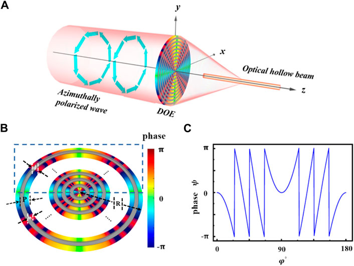
Figure 1. (A) Realization of the hollow beam by passing an angularly polarized light through the designed DOE. (B) Schematic of the DOE. The colored rings represent the transmitted region with a modulated phase, and the gray rings denote areas that are opaque. (C) Phase distribution for a half cycle when
Here,
where
Further,
where N is the cumulative coefficient and the maximum value of n. In theory, we can take values of N from 1 to infinity. Considering the manufacturing technique of DOE, we chose N = 3 in the simulation. Thus,
For an angularly polarized light,
In this study, the genetic algorithm was employed to optimize the DOE for realizing a sub-diffraction hollow beam with an excellent performance. In the simulation, we choose titanium dioxide as the material for the phase modulation region of the DOE and silicon as the material for the opaque region, respectively. For the optimization process, we assume the modulation factors of phase distribution to be

Figure 2. Hollow beam generated by the DOE with
However, the high-energy side lobe is almost adjacent to the hollow beam, and thus, severely restricts its applicability in different fields. To overcome this shortcoming, the energy on the side lobe of the hollow beam needs to be minimized.
Since the role of n is to adjust the overall light intensity of the hollow beam, and the light field intensity when
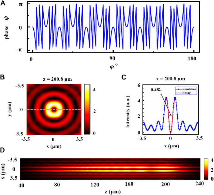
Figure 3. Hollow beam generated by the DOE with
This is due to the fact that when m increases to 6, the number of complex phase changes also increases from 3 to 6, and this drastic phase change causes a redistribution of light field energy, so that the high-energy side lobe is pushed away from the central light field [28]. Evidently, a high-energy side lobe region coexists with the subwavelength features. In contrast, the low-energy side lobe is usually accompanied by large structural features. The uniquely designed DOE enabled a remarkable reduction in side-lobe energy while still retaining the subwavelength character.
Furthermore, we examined the dependence of the length and FWHM of the hollow beam on the DOE period. Considering the manufacturing technology as well as the subwavelength structure, we choose the period P of the DOE from 2.2
where FWHM max and FWHM min are the maximum and minimum sizes of the generated hollow beam along the propagation distance.

Figure 4. (A) Relationship between FWHM and Length of the hollow beam and the DOE period
As indicated in Figure 4B, the uniformity of the hollow beams is greater than 96% when
The aforementioned results indicate that a customizable hollow beam can be generated using the proposed DOE, which features a periodical annular structure. Each ring in this DOE structure has a complex phase, which is determined by the modulation factors
In summary, we theoretically proposed a novel DOE for generating highly tunable hollow beams. The DOE consists of concentric rings with a phase that varies non-monotonically in the angular direction. By tuning the parameters of the DOE, such as its period, the size and propagation length of the generated hollow beam can be regulated from 0.43
In the future, we will explore methods to extend the length of a hollow beam to the millimeter scale while keeping the transverse FWHM below the diffraction limit. Additionally, we will investigate how to generate a localized hollow beam array with transverse and longitudinal FWHMs below the diffraction limit while maintaining uniform light intensity.
The raw data supporting the conclusion of this article will be made available by the authors, without undue reservation.
CS: Conceptualization, Data curation, Formal Analysis, Investigation, Methodology, Project administration, Software, Supervision, Validation, Visualization, Writing–original draft, Writing–review and editing. QW: Conceptualization, Data curation, Formal Analysis, Investigation, Methodology, Project administration, Software, Supervision, Validation, Visualization, Writing–original draft, Writing–review and editing. JL: Conceptualization, Data curation, Formal Analysis, Investigation, Software, Visualization, Writing–original draft, Writing–review and editing. WW: Data curation, Formal Analysis, Software, Supervision, Writing–original draft, Writing–review and editing. DL: Funding acquisition, Investigation, Supervision, Validation, Writing–original draft, Writing–review and editing. ZC: Data curation, Formal Analysis, Supervision, Validation, Writing–original draft, Writing–review and editing. MG: Conceptualization, Data curation, Formal Analysis, Funding acquisition, Investigation, Methodology, Project administration, Software, Supervision, Validation, Visualization, Writing–original draft, Writing–review and editing.
The author(s) declare financial support was received for the research, authorship, and/or publication of this article. This study was supported by the National Natural Science Foundation of China (Grant No. 62375089), Guangdong Basic and Applied Basic Research Foundation (Grant No. 2022A1515140139), the Innovation Program for Quantum Science and Technology (Grant No. 2021ZD0303401) and Quantum Science Strategic Project of Guangdong Province (Grant No. GDZX2306004).
The authors declare that the research was conducted in the absence of any commercial or financial relationships that could be construed as a potential conflict of interest.
All claims expressed in this article are solely those of the authors and do not necessarily represent those of their affiliated organizations, or those of the publisher, the editors and the reviewers. Any product that may be evaluated in this article, or claim that may be made by its manufacturer, is not guaranteed or endorsed by the publisher.
1. Duocastella M, Arnold CB. Bessel and annular beams for materials processing. Laser Photon Rev (2012) 6(5):607–21. doi:10.1002/lpor.201100031
2. Weber N, Spether D, Seifert A, Zappe H. Highly compact imaging using Bessel beams generated by ultraminiaturized multi-micro-axicon systems. JOSA A (2012) 29(5):808–16. doi:10.1364/josaa.29.000808
3. Rogers ET, Zheludev NI. Optical super-oscillations: sub-wavelength light focusing and super-resolution imaging. J Opt (2013) 15(9):094008. doi:10.1088/2040-8978/15/9/094008
4. Gan Z, Cao Y, Evans RA, Gu M. Three-dimensional deep sub-diffraction optical beam lithography with 9 Nm feature size. Nat Commun (2013) 4(1):2061. doi:10.1038/ncomms3061
5. Peng F, Yao B, Yan S, Zhao W, Lei M. Trapping of low-refractive-index particles with azimuthally polarized beam. JOSA B (2009) 26(12):2242–7. doi:10.1364/josab.26.002242
6. Glushko B, Kryzhanovsky B, Sarkisyan D. Self-phase-matching mechanism for efficient harmonic generation processes in a ring pump beam geometry. Phys Rev Lett (1993) 71(2):243–6. doi:10.1103/physrevlett.71.243
7. Padgett M, Allen L. The angular momentum of light: optical spanners and the rotational frequency shift. Opt Quan Electron (1999) 31:1–12. doi:10.1023/a:1006911428303
8. La PA, Wang MD. Optical torque wrench: angular trapping, rotation, and torque detection of quartz microparticles. Phys Rev Lett (2004) 92(19):190801. doi:10.1103/physrevlett.92.190801
9. Liu T, Tan J, Liu J, Lin J. Creation of subwavelength light needle, equidistant multi-focus, and uniform light tunnel. J Mod Opt (2013) 60(5):378–81. doi:10.1080/09500340.2013.778343
10. Yu Y, Huang H, Zhou M, Zhan Q. Engineering of multi-segmented light tunnel and flattop focus with designed axial lengths and gaps. Opt Commun (2018) 407:398–401. doi:10.1016/j.optcom.2017.09.075
11. Zeng Y, Chen M, Lin S, Huang H, Wu P, Zhou M, et al. Creating a spatial optical tube of prescribed characteristics. Opt Commun (2022) 506:127581. doi:10.1016/j.optcom.2021.127581
12. Chen J, Xu Q. Superlong uniform light tunnel created by focusing radially polarized vortex beam. J Appl Phys (2018) 124(4). doi:10.1063/1.5033926
13. Qin F, Huang K, Wu J, Teng J, Qiu CW, Hong M. A supercritical lens optical label-free microscopy: sub-diffraction resolution and ultra-long working distance. Adv Mater (2017) 29(8):1602721. doi:10.1002/adma.201602721
14. Zhu X, Fang W, Lei J, Li Z, Xie F, Cao Y, et al. Supercritical lens array in a centimeter scale patterned with maskless UV lithography. Opt Lett (2020) 45(7):1798–801. doi:10.1364/ol.389702
15. Rogers ET, Lindberg J, Roy T, Savo S, Chad JE, Dennis MR, et al. A super-oscillatory lens optical microscope for subwavelength imaging. Nat Mater (2012) 11(5):432–5. doi:10.1038/nmat3280
16. Wu Z, Jin Q, Zhang S, Zhang K, Wang L, Dai L, et al. Generating a three-dimensional hollow spot with sub-diffraction transverse size by a focused cylindrical vector wave. Opt Express (2018) 26(7):7866–75. doi:10.1364/oe.26.007866
17. Chen G, Wu Z-X, Yu A-P, Zhang Z-H, Wen Z-Q, Zhang K, et al. Generation of a sub-diffraction hollow ring by shaping an azimuthally polarized wave. Scientific Rep (2016) 6(1):37776. doi:10.1038/srep37776
18. Huang K, Shi P, Cao G, Li K, Zhang X, Li Y. Vector-vortex bessel–gauss beams and their tightly focusing properties. Opt Lett (2011) 36(6):888–90. doi:10.1364/ol.36.000888
19. Wang H, Shi L, Lukyanchuk B, Sheppard C, Chong CT. Creation of a needle of longitudinally polarized light in vacuum using binary Optics. Nat Photon (2008) 2(8):501–5. doi:10.1038/nphoton.2008.127
20. He J, Zhuang J, Ding L, Huang K. Optimization-free customization of optical tightly focused fields: uniform needles and hotspot chains. Appl Opt (2021) 60(11):3081–7. doi:10.1364/ao.418415
21. Wang S, Li X, Zhou J, Gu M. Ultralong pure longitudinal magnetization needle induced by annular vortex binary Optics. Opt Lett (2014) 39(17):5022–5. doi:10.1364/ol.39.005022
22. Diao J, Yuan W, Yu Y, Zhu Y, Wu Y. Controllable Design of super-oscillatory planar lenses for sub-diffraction-limit optical needles. Opt Express (2016) 24(3):1924–33. doi:10.1364/oe.24.001924
23. Chen G, Wu Z, Yu A, Zhang K, Wu J, Dai L, et al. Planar binary-phase lens for super-oscillatory optical hollow needles. Scientific Rep (2017) 7(1):4697. doi:10.1038/s41598-017-05060-2
24. Zhang S, Chen H, Wu Z, Zhang K, Li Y, Chen G, et al. Synthesis of sub-diffraction quasi-non-diffracting beams by angular spectrum compression. Opt Express (2017) 25(22):27104–18. doi:10.1364/oe.25.027104
25. Amidror I. The fourier-spectrum of circular sine and cosine gratings with arbitrary radial phases. Opt Commun (1998) 149(1-3):127–34. doi:10.1016/s0030-4018(98)80006-0
26. Huang K, Ye H, Teng J, Yeo SP, Luk’yanchuk B, Qiu CW. Optimization-free superoscillatory lens using phase and amplitude masks. Laser Photon Rev (2014) 8(1):152–7. doi:10.1002/lpor.201300123
Keywords: tunable hollow beams, complex phase, diffraction limit, azimuthally polarized wave, full width at half maximum
Citation: Sun C, Wang Q, Liang J, Wang W, Liu D, Chen Z and Gu M (2024) Theoretical realization of tunable hollow beams using a periodical ring structure with a complex phase. Front. Phys. 12:1383835. doi: 10.3389/fphy.2024.1383835
Received: 08 February 2024; Accepted: 10 May 2024;
Published: 24 May 2024.
Edited by:
Hao Hu, Nanjing University of Aeronautics and Astronautics, ChinaReviewed by:
Giuseppe Brunetti, Politecnico di Bari, ItalyCopyright © 2024 Sun, Wang, Liang, Wang, Liu, Chen and Gu. This is an open-access article distributed under the terms of the Creative Commons Attribution License (CC BY). The use, distribution or reproduction in other forums is permitted, provided the original author(s) and the copyright owner(s) are credited and that the original publication in this journal is cited, in accordance with accepted academic practice. No use, distribution or reproduction is permitted which does not comply with these terms.
*Correspondence: Dongmei Liu, ZG1saXVAc2NudS5lZHUuY24=; Min Gu, bWluZ3VAbS5zY251LmVkdS5jbg==
†These authors have contributed equally to this work and share first authorship
Disclaimer: All claims expressed in this article are solely those of the authors and do not necessarily represent those of their affiliated organizations, or those of the publisher, the editors and the reviewers. Any product that may be evaluated in this article or claim that may be made by its manufacturer is not guaranteed or endorsed by the publisher.
Research integrity at Frontiers
Learn more about the work of our research integrity team to safeguard the quality of each article we publish.