 Xuan Zhang
 Shangmin Lin
 Hu Wang1,2,3,4
- 1School of Optoelectronic Engineering, Xi’an Technological University, Xi’an, China
- 2Xi’an Institute of Optics and Precision Mechanics, Chinese Academy of Sciences, Xi’an, China
- 3School of Optoelectronics, University of Chinese Academy of Sciences, Beijing, China
- 4Xi’an Space Sensor Optical Technology Engineering Research Center, Xi’an, China
The accuracy of the pointing error in the subreflector is of great importance to the large steerable radio telescope, so the measurement of the six degree-of-freedom (DOF) poses of the subreflector is crucial, which are measured by the detector and the laser array. The errors in the pose measurement system of the subreflector contain random measure errors and fitting iteration errors; all of them will add up to the pose measurement, which affects the accuracy of the six DOF parameters. This paper proposed the accuracy analysis method in the pose measurement of the subreflector of large antennas, which includes the error in the variable model in laser three-dimensional point space linear fitting, iterative accuracy analysis of spatial equations in Newton’s downhill method, and the analysis of the adjustment theory of the Bursa model. The experimental results show that the measure time in six-DOF poses of the subreflector in a large-aperture antenna is at most 0.5 s, while the measurement accuracy error of translation is within 0.0131 mm and the error of rotation is within 0.2323°, which indicates that the pose measurement method of the subreflector in large antennas based on stereo structured light is efficient and applicable enough to analyze the measurement system accuracy.
1 Introduction
Recently, with the further implementation of radio astronomy observation, international deep space exploration will face new challenges such as more distant communication distance and higher precision of deep space navigation, and the performance requirements of large aperture antennas will be higher and higher. With the in-depth research on related compensation methods, there is an urgent need to carry out research on the influence of various types of errors on the compensation effect in the process of service performance compensation in order to achieve the robustness of service performance compensation. The influence of complex environmental factors on the antenna’s electrical performance is inevitable, and the space for antenna service performance improvement is getting smaller and smaller. Therefore, how to ensure the excellent and robust service performance of antennas in complex environments is an important research direction in this field in the future.
Large-aperture reflector antennas are highly susceptible to changes in the reflector surface shape and pose deviation in complex environments such as wind, thermal, and gravity, which results in the reduced antenna efficiency. The subreflector surface pose error will cause changes in the optical path difference of the whole aperture surface, which eventually leads to the degradation of the antenna performance [1, 2]. It is an effective method to achieve electrical performance compensation through the active adjustment of the subreflector, which requires an accurate measurement and evaluation of the antenna subreflector. Many large-aperture antennas improved the measurement accuracy of the antenna through subreflector surface compensation methods, such as the American 100-m Green Bank Telescope (GBT) [3, 4], the Italian 64-m Sardinia Radio Telescope (SRT) [5], the 65-m Shanghai Radio Telescope [6, 7], the Guizhou Five-hundred-meter Aperture Spherical radio Telescope (FAST) [8], and the Qitai 110-m Radio Telescope (QTT) [9]. In order to reduce the defocusing effect caused by the deformation of the GBT antenna structure, White et al. [4] adjusted the subreflector surface through the Stewart mechanism with six degree-of-freedom (DOF) to achieve focus matching and feed cabin phase center adjustment. Wang et al. [5] used a position-sensitive detector (PSD) for SRT antenna subreflector pose measurement and experimentally verified it with laser trackers. The measurement accuracy was better than ±2
Structured light measurement technology has advantages such as simple installation, high accuracy, speed, and low cost. It has become a noncontact, three-dimensional pose or metrology measurement technology that researchers are devoted to researching and has made outstanding contributions [12–14]. Wan et al. [14] created the new forms of ultra-DOF structured light, which exhibited their power in increasing information capacity and safety. Iwasa et al. [15] proposed a high-resolution surface shape measurement system incorporating a grating projection method and a virtual-target registration method in the parabola antenna reflector with a diameter of 1.5 m, which offered an effective high-resolution noncontact surface shape measurement system for large space structures. Movable subreflector active compensation of the 110-m QTT antenna system is required to improve the adjustment accuracy under all working conditions, and its position needs to be detected in real time and with high precision, which presents greater challenges in the large-aperture antenna measurement. In our previous work, we proposed a method based on PSD and a multipoint structured light laser array without an optical system to measure the six DOF poses of the subreflector, which can measure the pose information in the subreflector at a distance of 5.78 m with seconds and retain the position and rotation error within 0.014 mm and 0.37°, respectively [16]. Based on the previous research, this paper proposed the accuracy analysis method in the pose measurement of the subreflectors of 110 m QTT, which includes the error in the variable (EIV) model in laser three-dimensional point space linear fitting, iterative accuracy analysis of spatial equations in Newton’s downhill method, and the analysis of the adjustment theory of the Bursa model. Compared with the previous work, this paper improved the algorithm, increased the measurement precision, and decreased the measurement time for subreflector pose detection, which verified the enforceability through error analysis. More importantly, this paper solved the limitations to the previous work for the greater variation in the subreflector surface pose angle and the local iterations. The main contributions in this work are threefold:
(1) The EIV model is applied to evaluate error in multipoint structured light laser beam three-dimensional point space line fitting, which provides the accuracy guarantee for the subsequent subreflector surface pose measurement.
(2) Newton’s downhill method is applied to estimate the spatial equations for iterative accuracy analysis, which solves the limitation in local iterations and decreases the measurement time.
(3) The Bursa model is used to calculate the six DOF poses of the antenna subreflector, which solves the limitations of the greater variation in the subreflector surface pose angle and improves the measurement accuracy.
The structure of the rest of this paper is as follows: Section 2 provides basic methods for error models and precision analysis; Section 3 presents the detailed experiments and data analysis results; and Section 4 draws the conclusions of this work.
2 Materials and methods
This paper analyzes the EIV model in laser three-dimensional point space linear fitting, the iterative accuracy of spatial equations in Newton’s downhill method, and the adjustment theory of the Bursa model.
2.1 Proposed method for the antenna subreflector pose measurement
This paper analyzes the EIV model in laser three-dimensional point space linear fitting, the iterative accuracy of spatial equations in Newton’s downhill method, and the adjustment theory of the Bursa model. As shown in Figure 1, the laser beam array group is placed in the center of the feed cabin, and the detector is installed in the subreflector, which is used to receive the laser beam spots. We first build a structured light laser beam array system and detection system to capture the two-dimensional position coordinates of laser spots. Second, multiple sets of laser spot position data are used for least squares fitting to obtain multiple spatial straight lines, and the accuracy is evaluated by the EIV model to meet the accuracy requirements. Then, we iterate the space equation of a structured light laser beam using Newton’s downhill method to obtain the three-dimensional position coordinates of the laser spots, which solved the limitation in local iterations and decreased the measurement time. Finally, the Bursa model is used to convert the three-dimensional position coordinates of the laser spots to the reference coordinates, obtaining six degrees of freedom parameters for the change in the subreflector surface pose, and the accuracy is evaluated in adjustment theory. The flow chart of the pose measurement system is shown in Figure 2.

Figure 1. Diagram of pose measurement analysis of the subreflector of large antennas.

Figure 2. Flowchart of the pose measurement system.
2.2 Error models in the antenna subreflector pose measurement system
2.2.1 Error model in spatial linear fitting
As shown in Figure 3, multiple sets of emitted laser beams are fitted by the principle of least squares to capture the spatial straight lines. The spatial linear equation can be expressed as follows:
where
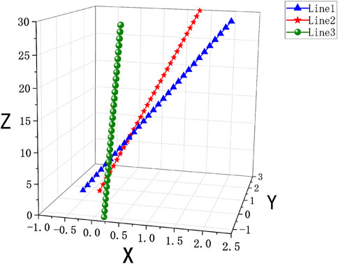
Figure 3. Spatial linear fitting.
Equation 1 can be formulated as follows:
Assuming a total of n sets of measured laser spot points, Eq. 2 can be expressed as follows:
Equation 3 can be formulated as follows:
The multiple linear equations can be expressed as follows:
where
Then, the EIV model is used to evaluate the precision of linear equations, which can be expressed as follows:
where V is the error term, B is the coefficient matrix with vectors of observations, L is the observation vector, and
where
Equation 10 needs to follow the same principles as Eq. 11, as follows:
where the coordinates of each point are considered independent observations of the same precision so that P is a unit matrix, and
Finally, the accuracy of the laser spot observations is evaluated, and the unit weighted medium error
where N is total observation data, containing
2.2.2 Newton’s downhill method for intersecting spot centroid coordinate solving
According to the principle of equal spatial line segment length, the relational expressions between the two-dimensional coordinates and the three-dimensional coordinates of the detector spots are as follows:
where
In order to solve Eq. 14, we use Newton’s downhill method to iterate the solution of the equation, which gives random initial values to speed up convergence while avoiding local convergence. Newton’s downhill can be expressed as follows:
where
2.2.3 Error model for pose acquisition with six DOFs
In the previous work [16], a simplified Bursa model was used to analyze the 7-parameter transformation from the two-dimensional coordinates of the detector laser spot centroid to the three-dimensional coordinates of the antenna system space coordinate system. Based on this, we propose the large-angle spatial coordinate transformation Bursa model and analyze the measurement precision in the subreflector pose of the large-aperture antenna with adjustment theory.
The Bursa model is expressed as follows:
where
The rotation matrix R can be expressed as follows:
Equation 16 can be expanded by the Taylor series at the initial values of the seven parameters
where
Equation 19 can be transformed as follows:
where
Based on Eqs 16–22, six DOF optimal estimates can be solved by iterative computation through the least squares method. The iterative process is as follows:
1) Select the initial values of the parameters: all parameters are set to 0 except
2) Substitute the initial values of the parameters into Eq. 16, and calculate the matrix
3) Solve the estimates
4) Check whether
5) Estimate the six DOFs with precision.
Finally, the subreflector pose transform in a large-aperture antenna is obtained by solving the six-DOF coordinate changes in PSD.
3 Experiments and results
3.1 Experimental platform
The pose measurement system is built for theory verification in the subreflector pose measurement in a large-aperture antenna. As shown in Figure 4, the multipoint structured light laser emission system is fixed on the test bench, which emits beams of lasers with a 650-nm wavelength, and the detection system is fixed on the two-dimensional translation platform. Multipoint structured light is mainly used to obtain spatial pose information from multiple laser beams through high-precision calibration. More equipment parameter details can be found in our previous study [16].
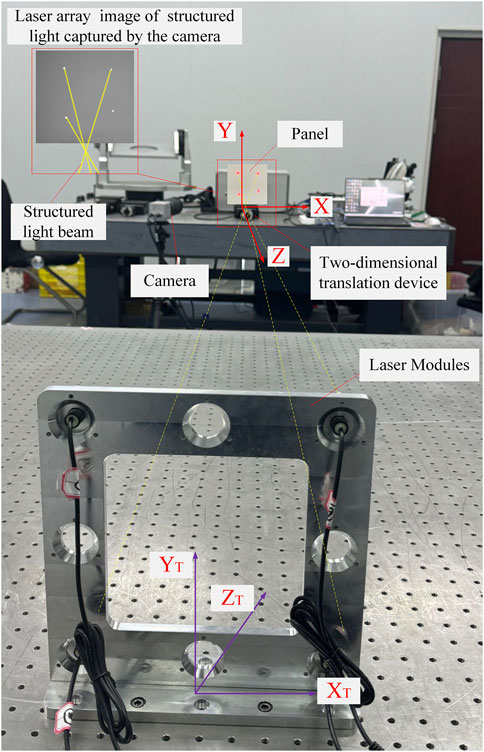
Figure 4. Laser emission system and the two-dimensional translation device.
The hardware server configuration for the experiments is an Intel (R) Core (TM) i7-12700F processor, NVIDA GeForce GTX 3080 graphics card with 10 GB of RAM. The software environments are Python 3.10.1 and PyCharm 2020.1. The proposed method in this paper utilizes several libraries, such as NumPy, Matplotlib, and OpenCV.
3.2 Simulation results and analyses
The three space linear fitting equations can be solved by Eqs 1–7 combined with captured data of space spots, and the three space linear fitting equations with the EIV model can be calculated by Eqs 8–12. Finally, the unit weighted medium error

Table 1. Space linear fitting equations and errors.
According to Table 1, it can be seen that the unit weighted medium error
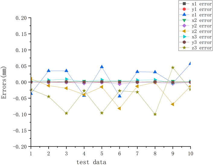
Figure 5. Error between the iterative results and the measured values of three-dimensional coordinates by the last 10 groups test data.
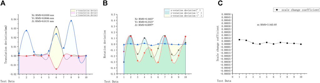
Figure 6. Last 10 groups of pose measurement errors. (A) Translation deviation. (B) Rotation deviation. (C) Scale change coefficient.
4 Conclusion
In this paper, the EIV model is applied to evaluate error in multipoint structured light laser beam three-dimensional point space line fitting, which provides the accuracy guarantees for the subsequent subreflector surface pose measurement; Newton’s downhill method is applied to estimate the spatial equations for iterative accuracy analysis, which solves the limitation in local iterations and decreases the measurement time. The Bursa model is used to calculate the six DOF poses of the antenna subreflector, which solves the limitations of the greater variation in the subreflector surface pose angle and improves the measurement accuracy. The results prove that the proposed method can be applied to the measurement of the antenna subreflector and ensure its high precision (translation deviation RMSmax = 0.0131 mm, rotation deviation RMSmax = 0.2323°, and scale coefficient RMS = 3.16 × 10⁻⁵) rapidly (time less than 0.5 s). In our future work, we will focus on a more accurate and faster model for the subreflector pose measurement of the large-aperture antennas and a more generalizable model error analysis.
Data availability statement
The original contributions presented in the study are included in the article/Supplementary Material; further inquiries can be directed to the corresponding author.
Author contributions
XZ: writing–original draft, writing–review and editing, conceptualization, data curation, formal analysis, investigation, methodology, software, and validation. SL: conceptualization, methodology, and writing–review and editing. HW: funding acquisition, resources, supervision, and writing–review and editing. MG: conceptualization, resources, supervision, validation, and writing–review and editing. YJ: writing–review and editing. HL: validation, writing–review and editing. YL: writing–review and editing.
Funding
The author(s) declare that financial support was received for the research, authorship, and/or publication of this article. The study was supported by the National Key Research and Development Program of China (grant no. 2021YFC2203501), the National Natural Science Foundation of China (NSFC) (grant no. 11803075), the Western Young Scholars of Chinese Academy of Sciences (grant no. XAB2022YN09), and the Natural Science Basic Research Program of Shaanxi (grant no. 2024JC-YBMS-536).
Conflict of interest
The authors declare that the research was conducted in the absence of any commercial or financial relationships that could be construed as a potential conflict of interest.
Publisher’s note
All claims expressed in this article are solely those of the authors and do not necessarily represent those of their affiliated organizations, or those of the publisher, the editors, and the reviewers. Any product that may be evaluated in this article, or claim that may be made by its manufacturer, is not guaranteed or endorsed by the publisher.
References
1. Duan BY, Wang CS. Reflector antenna distortion analysis using MEFCM. IEE Transactions on Antennas and Propagation (2009) 57:3409–13. doi:10.1109/TAP.2009.2028703
2. Fan F, Qian HL, Chen DK, Shen SZ. Research on key technologies of giant radio telescope structure. In: Journal of building structures (2023). p. 129–140. doi:10.14006/j.jzjgxb.2022.C106
3. Nikolic B, Prestage RM, Chandler DS, Hills CJ, Hills RE. Out-of-focus holography at the Green Bank Telescope. Astron Astrophysics (2007) 465(2):685–93. doi:10.1051/0004-6361:20065765
4. White E, Ghigo FD, Prestage RM, Frayer DT, Maddalena RJ, Wallace PT, et al. Green Bank Telescope: overview and analysis of metrology systems and pointing performance. Astron Astrophysics (2022) 659:A113. doi:10.1051/0004-6361/202141936
5. Wang CS, Xiao L, Xiang BB, Wang W, Qian X, Jiang L, et al. Development of active surface technology of large radio telescope antennas. Scientia Sinica Physica, Mechanica & Astronomica (2017) 47:059503. doi:10.1360/SSPMA2017-00011
6. Yang DH, Cheng Y, Wu CC, Jin ZY. A novel hexapod and its prototype for secondary mirror alignment in telescopes. Res Astron Astrophysics (2018) 18:115. doi:10.1088/1674-4527/18/9/115
7. Jiang YC, Wang JQ, Gou W, Yu LF, Jiang YB, Observatory SA. The measurement of sub-reflflector’s displacements of large radio telescopes by PSD method. Acta Astronomica Sinica (2019) 98–107. doi:10.15940/j.cnki.0001-5245.2019.06.009
8. Duan BY, Qiu YY, Zhang FS, Zi B. On design and experiment of the feed cable-suspended structure for super antenna. Mechatronics (2009) 19:503–9. doi:10.1016/j.mechatronics.2008.11.018
9. Wang N. Xinjiang Qitai 110 m radio telescope. Scientia Sinica (2014) 44:783–94. doi:10.1360/sspma2014-00039
10. Yan YF, Xue S, Hu XL, Lian PY, Xu Q, Wang N, et al. Progress and challenges in electromechanical coupling of radio telescopes. Int J Antennas Propagation (2022) 1–21. doi:10.1155/2022/4728303
11. Hou Y, Duan Y, Dou Y, Yao J, Zhao Y. Calibration of adjusting mechanism for subreflector of a 65 meters radio telescope. China Mech Eng (2013) 3318–22+3328. doi:10.3969/j.issn.1004-132X.2013.24.011
12. He C, Shen Y, Forbes A. Towards higher-dimensional structured light. Light: Sci Appl (2022) 11:205. doi:10.1038/s41377-022-00897-3
13. Wang Y, Zhou P, Yao CW, Wang HY, Lin B. High accuracy calibration method for multi-line structured light three-dimensional scanning measurement system based on grating diffraction. Opt Express (2024) 32:691–702. doi:10.1364/oe.496579
14. Wan ZS, Wang H, Liu Q, Fu X, Shen YJ. Ultra-Degree-of-Freedom structured light for ultracapacity information carriers. ACS Photon (2023) 10:2149–64. doi:10.1021/acsphotonics.2c01640
15. Iwasa T, Ota K, Harada T, Muramatsuet R. High-resolution surface shape measurement of parabola antenna reflector by using grating projection method with virtual targets. Acta Astronautica (2018) 153:95–108. doi:10.1016/j.actaastro.2018.09.031
Keywords: accuracy analysis, EIV, fitting iteration error, adjustment theory, Bursa model
Citation: Zhang X, Lin S, Wang H, Gao M, Jin Y, Lai Y and Lv H (2024) Optimization and accuracy analysis in pose measurement of the subreflectors of large antennas based on stereo structured light. Front. Phys. 12:1380434. doi: 10.3389/fphy.2024.1380434
Received: 01 February 2024; Accepted: 10 May 2024;
Published: 14 June 2024.
Edited by:
Ping Zhu, Chinese Academy of Sciences (CAS), ChinaReviewed by:
Carlos Frajuca, Federal University of Rio Grande, BrazilYijie Shen, Nanyang Technological University, Singapore
Copyright © 2024 Zhang, Lin, Wang, Gao, Jin, Lai and Lv. This is an open-access article distributed under the terms of the Creative Commons Attribution License (CC BY). The use, distribution or reproduction in other forums is permitted, provided the original author(s) and the copyright owner(s) are credited and that the original publication in this journal is cited, in accordance with accepted academic practice. No use, distribution or reproduction is permitted which does not comply with these terms.
*Correspondence: Shangmin Lin, bHNtMTc1QDE2My5jb20=