
95% of researchers rate our articles as excellent or good
Learn more about the work of our research integrity team to safeguard the quality of each article we publish.
Find out more
ORIGINAL RESEARCH article
Front. Phys. , 26 July 2024
Sec. Medical Physics and Imaging
Volume 12 - 2024 | https://doi.org/10.3389/fphy.2024.1369574
This article is part of the Research Topic Development of Task Specific Phantoms and Test Objects for Medical Imaging View all 8 articles
 Tito Körner1
 Stefan Wampl1
 Lorenz Kiss1
 Gunpreet Oberoi1,2
 Ewald Unger1
 Wolfgang Birkfellner1
 Albrecht I. Schmid1*
Introduction: Phantoms mimicking tissue motion have become a valuable tool for quality control in various fields of medical physics including lung phantoms for image-guided radiotherapy and functional imaging in nuclear medicine or magnetic resonance imaging (MRI) in the body. In MRI, precise kinematic models are more difficult to realize owing to the requirements of MR-compatibility. Pneumatic stepper motors built entirely of non-conducting materials can be safely used in an MR environment, with pressurized air supply and switching residing outside the magnet room.
Methods: In this research, a torso phantom was built adopting a 3D-printed linear stepper drive for use with high-field MR scanners. It was possible to simulate respiratory motion of a 3D-printed left ventricle phantom using the stepper.
Results and discussion: Precise and accurate motion for a time of 15 min over a range of 8 cm were achieved with speeds up to 5.5 mm/s when the stepper was loaded with the left ventricle phantom. It was shown that the motor is an effective tool for quality control in multi-modal medical imaging.
Medical imaging in the body is a challenging task and requires proper phantoms to validate data acquisition and reconstruction. In particular, thorax and abdominal magnetic resonance imaging (MRI) or spectroscopy (MRS), but also positron-emission tomography (PET) and radiation therapy, have to take into account motion. Several sources of motion are present and can cause complications depending on the application. Breathing leads to bulk displacement of the heart, liver and other organs or tissues, including tumors. The beating heart and the resultant blood flow can cause severe imaging challenges as well as being potential markers of disease.
Motion phantoms for quality control are a widespread tool in medical physics, especially when dealing with 4D imaging protocols [1–4]. While precise positioning can easily be achieved by means of stepper motors, the situation is more complicated in the case of magnetic resonance imaging, where stray electromagnetic fields and metallic materials are to be avoided. Therefore, most imaging phantoms for MRI are still static in design [5, 6]. Pneumatic or hydraulic systems were proposed, for instance for robotic interventions [7, 8]. Pneumatic stepper motors are one possible technology for use in MRI, as described in the literature [9–11], because they require neither magnets, electric currents nor metal in the motor itself. The designs presented in [11] are of special interest. The drives can be manufactured easily by means of 3D printing and have been proven to be MR safe at 0.25 T. In this work modifications to the driver hardware and software of the T-63 stepper motor [11], enabling its utilization in a torso phantom for magnetic resonance imaging scanners operating at both 3 T and 7 T.
Phantoms representing the torso are challenging to build and thus not commonly available, especially when also featuring motion. Because of their size and hence mass, they need to be quite sturdy, thus most available phantoms have protruding edges at the end where the endplates are screwed on. Consequently, this design limits their application for the use with surface coils for better receive coil performance. Also, depending on the application, some flexibility in assembling can be a cost-efficient use of the phantom. Therefore, a phantom with seamless design and cylindrical cavities was developed, which can be accessed from one end, allowing the mimicking of anatomical structures like lungs, liver, etc. by placing static or moving inserts.
The presented phantom consists of three independent units. the container, the motion unit and the flow unit. The schematics of the setup is shown in Figure 1. All the controls are outside the scanner, only fluid filled tubes and tubes for compressed air link the controls to the motor and the phantom in the scanner room. The torso was made from PMMA, PLA was used for printing the motor, rack and the LV phantom. PMMA and PLA are regarded as soft-tissue equivalent in x-ray imaging, when this phantom will be used in x-ray or CT scans [12].
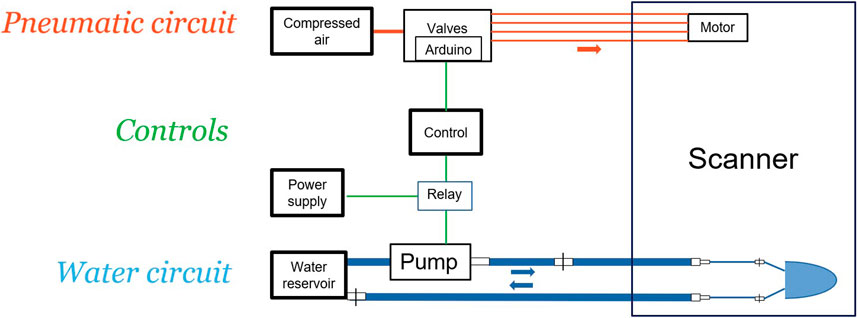
Figure 1. The pneumatic circuit (top) consists of the compressed air supply, supplying Arduino controlled valves driving the pneumatic stepper. The water circuit (bottom) makes use of a reservoir, from which a self-primed suction pump pumps water through tubes to the left ventricle phantom in the scanner room and back. A power supply (middle) supplies the pump, the Arduino board and valves and a raspberry pi (Control) to control the phantom. The box on the right indicates the scanner room, or even the phantom itself. Note, that only air and water supply pass through.
The original STL file of the stepper motor was taken from www.myminifactory.com/object/3d-print-t-63-pneumatic-linear-stepper-motor-98487. The motor requires four independently switchable pressure sources. The valves are electrically switched (Figure 1) and thus situated outside the magnet room. In the MR Centre, this translates into 10 m of tubing for the 7 T scanner and only marginally less for the 3 T. In consequence, the original 4 mm diameter tubing used for the T-63 design was inadequate due to the pneumatic resistance at this diameter. To realize a separation of 10 m from the control hardware to the drive, a bushing made of Perspex placed approximately 0.3 m from the drive was used. A 10 mm diameter pneumatic tube was glued into this bushing with cyanoacrylate glue (Loctite 406, Henkel CEE, Austria). For the remaining distance to the control room, 10 mm diameter tubing was used (PUN-10 × 1,5-BL, Festo GmbH, Austria) and the lines were held apart using small boards of plywood.
A compressor (Adler Kompressoren, Ulrich bei Steyr, Austria), with 75 L, max 13 bar) and an additional reservoir of 150 L (max 10 bar) was used as compressed air supply. The compressor was in a separate room and linked to the reservoir via a tube of 15 m with a diameter of 20 mm. The reservoir in the control room was then supplying the pneumatic stepper via switchable valves, see below. The maximum throughput is 460 L/min.
The solenoids controlling the air supply were two Festo VUVG-L10-T32C-MT-M5-1P3 (Festo GmbH, Austria). Figure 2 shows the in house developed and manufactured circuit to drive these magnetic valves. The printed circuit board designs, a bill of materials and the software to drive the T-63 can be found here: https://github.com/wbirk/PneumaticStepperControl/. The microcontroller used is an Adafruit Feather M4 Express (Adafruit Inc., NY/USA). It is programmed with Arduino IDE (version 1.8.19, www.arduino.cc). A program file for driving the T-63 can be found on the same github site. This file was adapted to enable the microcontroller to create the required motion patterns of the pneumatic stepper as described in Figure 3. The printed circuit board hosting the hardware was designed with Fritzing (www.fritzing.org) and the original layout as well as Gerber files are also provided.
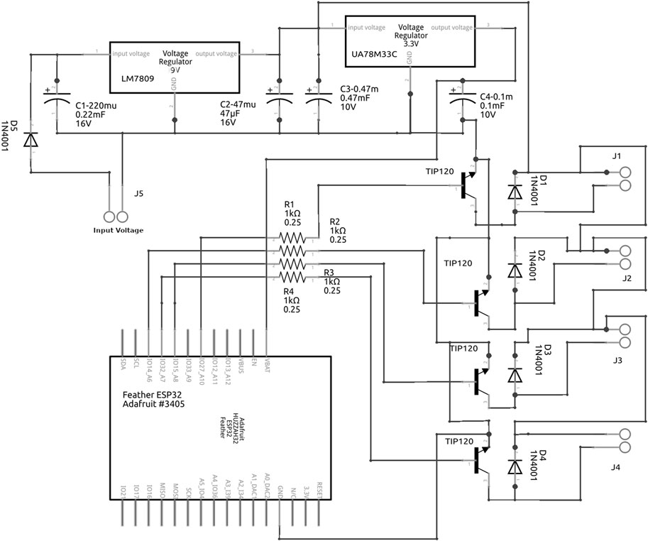
Figure 2. Schematic for the driver hardware, drawn with Fritzing, https://fritzing.org/. To operate the Festo valves, four TIP 120 Darlington transistors with snubber diodes were used as switches. The basic power supplied is 12 V DC, the necessary stable voltages of 3.3 V for the microcontroller and 5 V for the Festo solenoids is produced by two DC-DC converters.
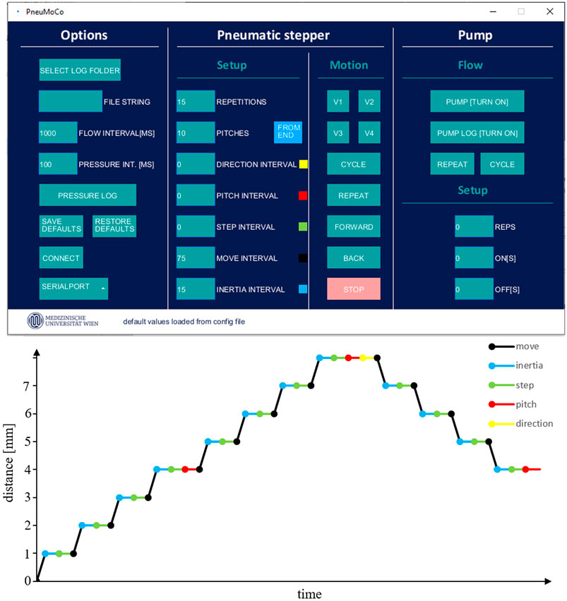
Figure 3. Top: The graphical user interface to control the phantom is shown. The basic unit of motion is one step. A full cycle of all four cylinders is called pitch and consists of the motion resulting from pressurizing each of the four chambers of the pneumatic stepper once in the correct order, for each direction (forward or backward). The speed of the stepper motion is controlled by time intervals which define how long each chamber is pressurized and the time in between the closing of one valve and opening of the next one. These parameters can be set in the “Setup” column (centre left). The coloured squares next to the interval names in the screenshot link these intervals to their position in the motion pattern of the pneumatic stepper in the graph below. • Repetitions: In case “Repeat” is selected in the “Motion” column (center right), this value determines how often the stepper is oscillating the rack back and forth. • Pitches: This value controls the distance the rack is moved in one direction. • Direction interval: When the linear stepper performs periodic motion, a delay when changing direction of the stepper rack can be added. • Step interval: The time in between two steps, which is added to the inertia interval. This value is used to control the speed of the linear motion. • Pitch interval: An additional delay can be added after each pitch. • Move interval: The amount of time a valve is open. If too small, steps are lost, if too long, a lot of compressed air will be lost, and the maximum speed of the stepper would be reduced. • Inertia interval: A solenoid valve should be opened only once the preceding valve is fully closed. It takes about 15 ms for a valve to fully close. This inertia parameter is the lower limit for steps. bottom: Illustration of the pneumatic stepper motion pattern: A step is the duration required for the motion caused by pressuring one chamber of the pneumatic stepper and the time delay until the next step. This time delay is determined by the move interval which is the time one valve is open (black line), the inertia interval (blue) giving the valve time to close before opening the next valve and the step interval (green) which is an additional delay that can be introduced before the next step. Four times a step (one for each chamber of the pneumatic stepper) is called a pitch and after each pitch an additional delay called pitch interval (red) can be added. Setting the direction interval adds a delay each time the pneumatic stepper changes direction. This figure shows two pitches in one direction and one pitch in the opposite direction, with each pitch consisting of four steps. Motion (vertical changes of the graph) only occur during move intervals (black lines).
To control the pneumatic stepper motor, a graphical user interface (GUI) was designed using the Processing IDE (Version 4.3, https://processing.org/) (Figure 3). The Processing code was compiled as a java application and executed on a Raspberry Pi with the “Raspberry Pi OS Buster” operating system. The desktop session can be accessed using virtual network computing (VNC) from external devices like laptops or smartphones. Commands are sent from the raspberry pi via USB to the Arduino board.
The timing and order of opening and closing of the valves determines the direction and speed of the motor. These parameters can be controlled using the GUI (Figure 3). The limits on these parameters which allow for a certain task depend on the air supply (pressure, pressure recovery rate, tube length), friction of the motor rack, and the load.
Using the GUI, the stepper can be moved in one direction for a certain number of steps or cycles. It can also perform periodic motion, going back and forth for a defined number of steps, either for a certain number of repetitions or continuously until it is stopped by the user. The valve actions are logged to a file.
The GUI allows waiting for the next trigger pulse at certain intervals, e.g., at the start or at the turning points, or even after a cycle.
The MRI pulse sequence can send a TTL signal via the external trigger output to synchronize the experiments. It needs sufficient length (3 ms) to be captured reliably by the Arduino, which has a sampling rate of 490 Hz.
A torso-shaped phantom (Figure 4) with a total length of 40 cm, a width of 33 cm and a height of 23 cm was designed and custom built (Chase GmbH, Maria Enzersdorf, Austria) in the material Perspex (PMMA). It features a seamless design and two open tubes (11 cm diameter) mimicking lungs integrated into the lid of the torso phantom. The lid also has an opening for filling the main container. It is mounted with screws to the phantom body on the inside such that nothing protrudes the body. 20 L of liquid are required to fill the phantom body. The phantom was filled with water, measured T1 values were 3.00 ± 0.35 s at 7 T (Stimulated Echo Acquisition Mode (STEAM), progressive saturation) and 2.69 ± 0.35 s at 3 T [Turbo Spin Echo (TSE), Inversion recovery] or 2.57 ± 0.21 s at 3T (STEAM, progressive saturation). A base plate holds the torso phantom in a matching opening. It also holds a 3D positioning table built in-house using PVC (Figure 5). This positioning table is used to place the pneumatic stepper at one of the open tubes in the lid of the torso phantom. As can be seen from Figure 5, a rack passes through the motor, with screw fittings cut to the front for mounting parts (Figure 4). Inserts, e.g., cylinders or other forms filled with solutions or gels, can thus be moved.
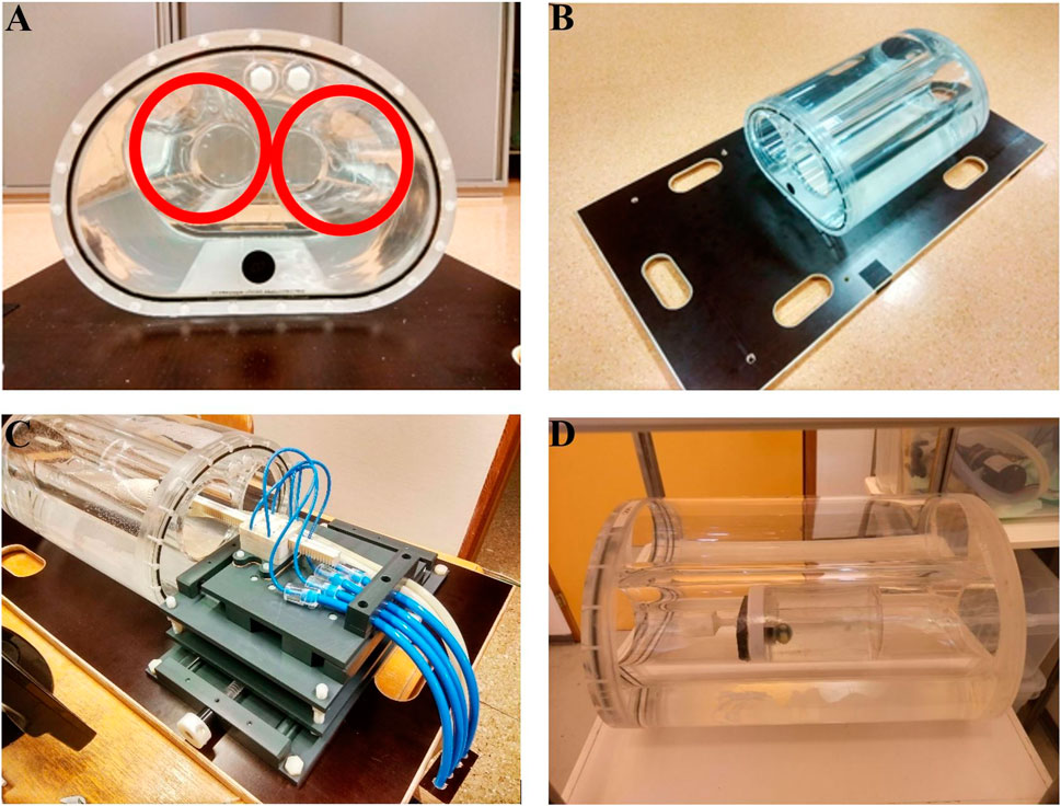
Figure 4. Photos of the torso phantom various setups. (A,B) The two cylindrical empty tubes of diameter 10 cm can be seen, making the inside of the phantom accessible (red circles). (C) The left ventricle phantom is mounted on the rack of the pneumatic motor, which is located in front of one of the hollow sections. The motor is mounted on an adjustable table to allow for correct positioning. A video showing the pneumatic stepper motor moving the left ventricle phantom in the torso phantom is provided in the Supplementary Video S1. (D) A fluid-filled cylinder is inserted in one of the tubes of the torso phantom. The cylinder has an aqueous solution of 50 mmol/L potassium diphosphate/potassium hydrogen phosphate (9:1 ratio). T1 was 0.11 ± 0.00 s at 7 T and 0.10 ± 0.02 s at 3 T. It also contains a small sphere of another phosphate solution (phenylphosphonic acid), which can be used for spectroscopy sequence tests and calibration.
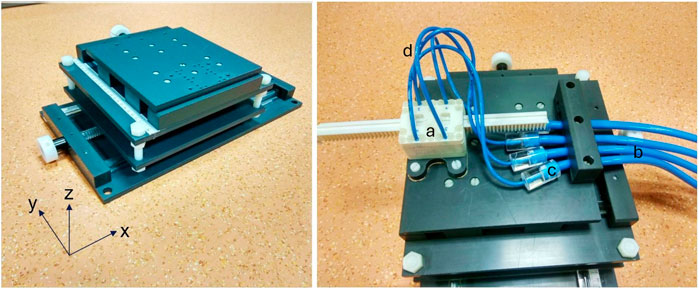
Figure 5. An in-house built 3D positioning table (left) is used with the pneumatic stepper (a) mounted on top (right). The four blue 10 mm diameter tubes (b) coming from the pneumatic valves are connected with Q20 bushings (c) to the 4 mm tubes (d) supplying the chambers of the pneumatic stepper.
A left ventricle-shaped two-chamber phantom (LV phantom, see Figure 6) was mounted on the rack of the pneumatic motor (Figure 4C). The LV phantom consists of an outer liquid filled compartment mimicking the myocardium, and an inner compartment with an in- and outlet that allows flow. To simulate blood flow, water is flushed through the inner compartment, supplied via 10 m long tubes using a self-priming pump (Jabsco “water-puppy”) with a 15 L water reservoir. To reduce friction losses in the long tubes, an inner diameter of ¾ inch was used, matching the diameter of the in- and outlet of the pump. Flexible tubes with an inner diameter of 8 mm were used for the first 30 cm before and after the LV phantom. The flexible short tubes allowed unrestricted motion of the LV phantom during the pneumatic motor movement. The 10 m tubes were equipped with a ¾ inch hose connector (Gardena Profi-System, Husqvarna Austria GmbH, Linz, Austria) on one side to connect with the short tubes from the pump on one end. On the other end a ¾ inch to 8 mm hose connector (Eheim GmbH & Co KG, Deizisau bei Stuttgart, Germany) was used. All connectors were equipped with valves to be able to (dis-)connect the tubes without loss of liquid. The flow rate was adjusted by varying the current of the pump’s power supply (Laboratory DC Power Supply, IPS 3303 RS Pro, RS Components Handelsges.m.b.H., Gmuend, Austria) using the power supply’s integrated controls and monitored using a flowmeter connected to the outlet of the pump. De/-activation of the pump was achieved using a relay, which was controlled by the Raspberry Pi.
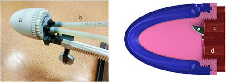
Figure 6. Left: A left ventricle phantom (a) is mounted at the tip of the pneumatic stepper rack with a wheel for additional load support (b). Right: The left ventricle phantom consists of an outer liquid filled compartment (blue) mimicking cardiac tissue and an inner compartment (pink) with inlet (c) and outlet (d) to achieve flow integrated into the lid (red). The removable spoiler (e) at the inlet causes turbulent flow for realistic flow characteristics.
Initially, calibration and testing were done on the bench. Visual inspection, markers on the rack and camera footage were used to evaluate the proper response of the motor. A demonstration of the motion is seen in Supplementary Video S1. The whole system was then put into both a 3 T PrismaFit and a 7 T Magnetom MR scanners (Siemens, Erlangen, Germany). A 14 × 22 cm2 surface coil (Rapid Biomedical, Rimpar, Germany) was used for 7 T excitation and acquisition of MR signals, while the spine array and the 18-channel flexible array were used at 3 T.
The electronically switched valves were placed outside the scanner room and connected via 10 m of tubing to the phantom. This required a nominal operating pressure of at least 9 bar at the valves to compensate for losses in the long tubes. The image quality of the phantom is good, even using a 7 T scanner and a comparatively small surface coil (Figure 7), inhomogeneities in the signal distribution are typical for 7 T MRI. The motor and rack are not visible, signal arises only from the liquid filling.
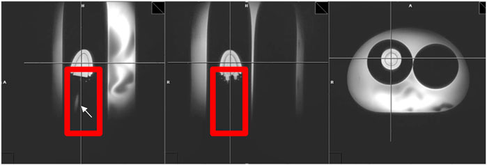
Figure 7. The planes of the sagittal view (left) and coronal view (middle) of these localizer images of the torso phantom in a 7 T scanner with the left ventricle phantom display the area where the left ventricle phantom is mounted (red rectangles). In the sagittal view a segment of an 8 mm tube is visible (white arrow), but no structures from the mount, stepper rack or related image artifacts are visible. This indicates that the material of the pneumatic stepper does not impair MR image quality. The vertical and horizontal lines in each image indicate the image plane of the other two images.
MRI scans were also performed in a Siemens PrismaFIT 3 T MR scanner using the spine array and 18 channel flexible body coil array for signal detection (Figure 8). Motion was performed and recorded in the LV phantom (T1 = 1.7 s at 3 T) with and without flow as well as in a cylindric vessel of 10 cm diameter and 15 cm length, filled with saline solution (T1 = 0.10 ms at 3 T, T1 = 0.11 ms at 7 T). The motor was set to repeatedly move forward and backward. This motion was performed during rapid MR imaging (Fast Low-Angle Shot (FLASH)) in a coronal slice (Figure 8), acquired repeatedly, the flip angle was set to 12°. TR = 5 ms, TE = 2 ms, FOV 300 × 186 mm, 1 × 1 mm2 in-plane resolution, slice thickness 7 mm. 512 images were acquired in total, one every 0.6 s. Obejct tracking using OpenCV (https://opencv.org/) and the kernelized correlation filter (KFC) [13] was used to capture motion based on the MR images, the implementation is described here [14], see Supplementary Video S2–S4. This was then plotted using PDL (https://pdl.perl.org/) and compared to predictions from motor settings and geometry.
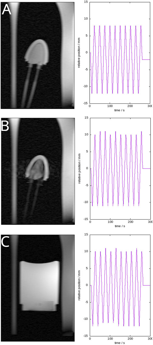
Figure 8. Moving compartment in one of the cylindrical openings of the phantom. The left column shows coronal slices of the compartment, either the ventricle (A,B) or the cylinder (C). Image B shows the ventricle while the pump is running, and water is flowing through the inner compartment. The supplying tubes are visible. The right column shows the recorded motion pattern. The insert was moving at a constant speed of 1.6 m/s for a maximal displacement of 20 mm. The videos are available as (Supplementary Video S2–S4, respectively). The scan resolution was 1 mm in plane. Sometimes the tracker was off by one pixel, as can be seen in plots, it was verified that this was not a problem of the phantom.
A torso phantom featuring a pneumatic stepper motor driving an in-house developed 3D printed two compartment left-ventricle shaped phantom was successfully built (Figure 4). It is inherently built as a modular system, each part working independently but fitting well together. All parts meant to be within the scanner are without metal. No electric, magnetic or electronic components are required within the Faraday cage, thus avoiding complications. Approximate material costs are summarised in Supplementary Table S1.
Using the left ventricle phantom, as described above and shown in Figures 8A,B a flow rate of 7 L/min was used, with flow velocities of ∼250 cm/s in the supplying tubes and maximum velocities in the ventricle inlets, which are the narrowest point in the circuit and limiting flow rates. Phase contrast MRI was also compared to flow meter readings and reservoir levels before and after flow, which agreed (MRI: 7.7 L/m, flow meter: 7.2 L/min, reservoir-based: 8 L/min). Motion was not impaired by flow (Figure 8B), some signal loss could be observed in the resulting images in areas with flowing media.
Moving the LV phantom was achieved with high reproducibility in terms of positioning the LV phantom and speed of the motor. The step size is 1 mm, the maximum range with the current rack is 20 cm. The step size was determined by the distance of two teeth on the rack (4 mm). The tubing involved significant loss in pressurised air each step, which reduced the maximum achievable speeds. This is further reduced if the piston is loaded with the ventricle phantom. In the unloaded case a maximum of 10 mm/s and when loaded with the LV phantom a maximum of 5.5 mm/s for at least 15 min of continuous oscillating motion with an amplitude of 8 cm was possible without losing steps. A maximum speed of 12 mm/s in the unloaded case and 7.5 mm/s when loaded with the LV phantom on the pneumatic motor rack were achievable for a short time. Image artefacts caused by the motor itself were negligible (Figures 7, 8).
We demonstrate here a phantom that features several components, a big torso, flow, motion and the potential for extension without loss of functionality. Materials are comparatively cheap, the most expensive was sourcing the big torso. The motor was built solely by additive manufacturing, which is, we think, new to the field. This helped in placing the motor very close to the target area for imaging. In fact, it can be within the volume of interest without interfering with MRI.
There are several commercial and non-commercial motion phantoms. Many use motors within the scanner, sufficiently distant to avoid most artefacts in the region of interest, e.g., [15]. A similar design as ours is commercially available, however with a much smaller volume and using electric propulsion (https://modusqa.com/products/quasar-mri4d-motion-phantom/). The presented phantom additionally offers flow capabilities and the option to switch to other inserts. In the current configuration the two cylinders with 10 cm diameter, which are integrated into the lid and make the inside of the phantom accessible, limit the geometry of the inlets, which can be used with the phantom. In the future lids with different designs integrating other geometries can be manufactured. This will potentially allow the use of different kinds of inlets like whole heart phantoms, or different organs.
The maximum flowrate using the LV phantom is within the physiological range. Resting cardiac output is about 5 L/min and can reach up to 36 L/min in trained athletes during strong exercise [16]. The flow rate through the LV phantom was evaluated using phase contrast MRI. Outside the magnet a reservoir-based approach was used. The time it took to fill the reservoir in between two levels was observed. The flow rate was then calculated by dividing the known volume difference by the elapsed time. This method is accurate to at least 0.1 L/min and shows good agreement with phase contrast MRI. The flow meter is an inexpensive model and probably cannot be trusted to a similar level of accuracy. Taking into account SNR, the resolution, slice thickness, etc. and that all experiments were taken one after the other, an accuracy of 10% is to be expected. Considering this, the values agree within expected accuracy limits.
Some phantoms use pneumatic pistons [17] or balloons [18, 19] which are not as accurate as a stepper, which allows arbitrary motion patterns to be programmed. There are also more anthropomorphic phantoms [20, 21] which have the drawback that their geometry is much more complicated and thus a ground truth harder to obtain.
The long distance between the controlling valves and the motor draws about 0.4 L of pressurized air from the air reservoir for each step of the motor, venting the pressurized air into the atmosphere when the step is completed. This is a limiting factor because valve timing had to be balanced between phantom speed and pressure recovery. A smaller tube diameter would reduce the draw per step, but the higher air resistance would limit the force of the motor for a pressure pulse with the same timing and thus its ability to push load without losing steps. If the valves could be placed closer to the motor, the duty cycle could be improved significantly. It should be noted that between the compressor in the equipment room and the switching unit were 15 m of tubing and a 150 L compressed air reservoir, due to noise restrictions and available space as well as power sockets in the lab. Maximising speed was not the primary goal of this work as it currently still is in the order of magnitude as human breathing. With a bigger motor, improving on materials by further reducing friction of the rack, and optimising the pneumatic tubing and switching, maximum movable mass, rack speed and range could certainly be increased.
First tests using less pressure revealed that the stepper motor sometimes lost steps when moving the rack back towards the stepper housing when the rack was far away from the stepper due to the weight of the left ventricle phantom mounted at the tip of the rack. The weight also caused permanent creep of the rack over the long term for the originally used material (PLA). A new rack was then 3D printed using Velo Pure White resin. It should be noted that the stepper is really accurate only to the step size. If a higher accuracy than 1 mm is required, a scaled version of the setup would be required.
The continuous supply with pressurized air is lower than the short term maximum demand of the pneumatic stepper at the highest tested speeds. Most MRI scans typically require less than 15 min of time. We were able to prove that a continuous oscillating motion of at least 15 min is achievable with the current setup.
The main phantom body holds 20 L of liquid with two cylindrical inserts. These can be filled by compartments, as desired. In contrast to PET- or CT-only phantoms, MR compatible phantoms have to provide sufficient loading for the RF coils. The large mass of the main phantom may be inconvenient in the handling but was chosen deliberately to provide appropriate RF coil loading. Also, this allows for evaluation of scan protocols intended for bigger parts of the body with transmit voltages comparable to in vivo situations. If desired, extensions mimicking legs or the neck and head could be mounted on the backside of the phantom, which is flat.
Here we evaluated our phantom in MRI only. Yet there is no reason why it should not be useful for other modalities, e.g., when filling the ventricle with radioactive tracers for PET or radiation planning, or adding CT contrast media. We have chosen MRI because this modality has the highest restrictions in the choice of materials when it comes to creating motion within the scanner.
We present here a whole system that should be able to address many needs of a torso phantom for evaluating imaging in the thorax and abdomen. Overall, the proposed setup proves that despite tremendous challenges like the long distance between the scanner and control room and the limitation of useable materials in the immediate vicinity of an MR scanner it is feasible to use a 3D printed pneumatic stepper to realize motion of an MR phantom.
The raw data supporting the conclusions of this article will be made available by the authors, without undue reservation.
TK: Conceptualization, Data curation, Investigation, Methodology, Software, Writing–original draft, Writing–review and editing, Funding acquisition, Resources, Visualization, Formal Analysis, Validation. SW: Writing–review and editing, Formal Analysis, Investigation, Methodology, Software, Validation, Visualization, Data curation, Writing–original draft. LK: Data curation, Formal Analysis, Investigation, Resources, Software, Validation, Visualization, Writing–review and editing. GO: Methodology, Writing–review and editing, Conceptualization, Investigation. EU: Investigation, Methodology, Resources, Writing–review and editing. WB: Funding acquisition, Project administration, Supervision, Writing–original draft, Investigation, Methodology, Resources, Software, Validation, Writing–review and editing, Conceptualization. AS: Writing–original draft, Conceptualization, Formal Analysis, Funding acquisition, Investigation, Methodology, Project administration, Resources, Software, Supervision, Validation, Visualization, Writing–review and editing.
The author(s) declare that financial support was received for the research, authorship, and/or publication of this article. This research was funded in whole, or in part, by the Austrian Science Fund (FWF) P 28867 and P 35607 awarded to AS. For the purpose of open access, the author has applied a CC BY public copyright licence to any Author Accepted Manuscript version arising from this submission. This research is also supported by the Focus Grant (call 2019) from the CMPBME of the Medical University of Vienna, awarded to TK.
Author GO was employed by the company Austrian Center for Medical Innovation and Technology (ACMIT).
The remaining authors declare that the research was conducted in the absence of any commercial or financial relationships that could be construed as a potential conflict of interest.
The author(s) declared that they were an editorial board member of Frontiers, at the time of submission. This had no impact on the peer review process and the final decision.
All claims expressed in this article are solely those of the authors and do not necessarily represent those of their affiliated organizations, or those of the publisher, the editors and the reviewers. Any product that may be evaluated in this article, or claim that may be made by its manufacturer, is not guaranteed or endorsed by the publisher.
The Supplementary Material for this article can be found online at: https://www.frontiersin.org/articles/10.3389/fphy.2024.1369574/full#supplementary-material
1. Hugo GD, Rosu M. Advances in 4D radiation therapy for managing respiration: Part I – 4D imaging. Z Med Phys (2012) 22(4):258–71. doi:10.1016/j.zemedi.2012.06.009
2. Fabri D, Zambrano V, Bhatia A, Furtado H, Bergmann H, Stock M, et al. A quantitative comparison of the performance of three deformable registration algorithms in radiotherapy. Z Med Phys (2013) 23(4):279–90. doi:10.1016/j.zemedi.2013.07.006
3. Segars WP, Tsui BMW, Cai J, Yin FF, Fung GSK, Samei E. Application of the 4D XCAT phantoms in biomedical imaging and beyond. IEEE Trans Med Imaging (2018) 37(3):680–92. doi:10.1109/tmi.2017.2738448
4. Kang Y, Shen J, Liu W, Taylor PA, Mehrens HS, Ding X, et al. Impact of planned dose reporting methods on Gamma pass rates for IROC lung and liver motion phantoms treated with pencil beam scanning protons. Radiat Oncol (2019) 14:108. doi:10.1186/s13014-019-1316-y
5. Filippou V, Tsoumpas C. Recent advances on the development of phantoms using 3D printing for imaging with CT, MRI, PET, SPECT, and ultrasound. Med Phys (2018) 45(9):e740–e760. doi:10.1002/mp.13058
6. Valladares A, Beyer T, Rausch I. Physical imaging phantoms for simulation of tumor heterogeneity in PET, CT, and MRI: an overview of existing designs. Med Phys (2020) 47(4):2023–37. doi:10.1002/mp.14045
7. Monfaredi R, Cleary K, Sharma K. MRI robots for needle-based interventions: systems and technology, rm as. Ann Biomed Eng (2018) 46(10):1479–97. doi:10.1007/s10439-018-2075-x
8. Groenhuis V, Siepel FJ, Veltman J, van Zandwijk JK, Stramigioli S. Stormram 4: an MR safe robotic system for breast biopsy. Ann Biomed Eng (2018) 46(10):1686–96. doi:10.1007/s10439-018-2051-5
9. Chen Y, Godage IS, Tse ZTH, Webster IIIRJ, Barth EJ. Characterization and control of a pneumatic motor for MR-conditional robotic applications. IEEE ASME Trans Mechatron (2017) 22(6):2780–9. doi:10.1109/tmech.2017.2767906
10. Stoianovici D, Jun C, Lim S, Li P, Petrisor D, Fricke S, et al. Multi-imager compatible, MR safe, remote center of motion needle-guide robot. IEEE Trans Biomed Eng (2018) 65(1):165–77. doi:10.1109/tbme.2017.2697766
11. Groenhuis V, Stramigioli S. Rapid prototyping high-performance MR safe pneumatic stepper motors. IEEE/ASME Trans Mechatronics (2018) 23(4):1843–53. doi:10.1109/tmech.2018.2840682
12. Hatamikia S, Jaksa L, Kronreif G, Birkfellner W, Kettenbach J, Buschmann M, et al. Silicone phantoms fabricated with multi-material extrusion 3D printing technology mimicking imaging properties of soft tissues in CT. Z Für Medizinische Physik (2023). doi:10.1016/j.zemedi.2023.05.007
13. Henriques JF, Caseiro R, Martins P, Batista J. High-speed tracking with kernelized correlation filters. IEEE Trans Pattern Anal Machine Intelligence (2015) 37:583–96. doi:10.1109/TPAMI.2014.2345390
14. Wampl S, Körner T, Meyerspeer M, Zaitsev M, Wolf M, Trattnig S, et al. Computer vision Object tracking on navigators in a modular, sequence-independent motion compensation pipeline, 2023, PREPRINT (Version 1) available at Research Square. doi:10.21203/rs.3.rs-3593302/v1
15. Einspänner E, Jochimsen TH, Harries J, Melzer A, Unger M, Brown R, et al. Evaluating different methods of MR-based motion correction in simultaneous PET/MR using a head phantom moved by a robotic system. EJNMMI Phys (2022) 9:15. doi:10.1186/s40658-022-00442-6
16. Bleifeld W, Hamm CW. Herz und Kreislauf: klinische Pathophysiologie. Berlin/Heidelberg/New York: Springer-Verlag (1987).
17. Wheatley M, De Deene Y. A novel anthropomorphic breathing phantom with a pneumatic MR-safe actuator for tissue deformation studies during MRI and radiotherapy. Physica Med (2022) 104:43–55. ISSN 1120-1797. doi:10.1016/j.ejmp.2022.10.017
18. De Tillieux P, Topfer R, Foias A, Leroux I, El Maâchi I, Leblond H, et al. A pneumatic phantom for mimicking respiration-induced artifacts in spinal MRI. Magn Reson Med (2018) 79:600–5. doi:10.1002/mrm.26679
19. Kim K, Jones P, Diederich C, Ozhinsky E. Technical note: Low-cost MR-compatible pneumatic respiratory organ motion simulator for the development of MR-guided thermal therapy. Med Phys (2022) 49:4365–71. doi:10.1002/mp.15783
20. Swailes NE, MacDonald ME, Frayne R. Dynamic phantom with heart, lung, and blood motion for initial validation of MRI techniques. J Magn Reson Imaging (2011) 34:941–6. doi:10.1002/jmri.22688
Keywords: torso phantom, MRI, stepper motor, 3D printing, additive manufacturing, pneumatic, modular phantom, breathing
Citation: Körner T, Wampl S, Kiss L, Oberoi G, Unger E, Birkfellner W and Schmid AI (2024) A modular torso phantom featuring a pneumatic stepper and flow for MR sequence development. Front. Phys. 12:1369574. doi: 10.3389/fphy.2024.1369574
Received: 12 January 2024; Accepted: 02 July 2024;
Published: 26 July 2024.
Edited by:
Elvis Chen, Western University, CanadaReviewed by:
Xirui Hou, Johns Hopkins University, United StatesCopyright © 2024 Körner, Wampl, Kiss, Oberoi, Unger, Birkfellner and Schmid. This is an open-access article distributed under the terms of the Creative Commons Attribution License (CC BY). The use, distribution or reproduction in other forums is permitted, provided the original author(s) and the copyright owner(s) are credited and that the original publication in this journal is cited, in accordance with accepted academic practice. No use, distribution or reproduction is permitted which does not comply with these terms.
*Correspondence: Albrecht I. Schmid, YWxicmVjaHQuc2NobWlkQG1lZHVuaXdpZW4uYWMuYXQ=
Disclaimer: All claims expressed in this article are solely those of the authors and do not necessarily represent those of their affiliated organizations, or those of the publisher, the editors and the reviewers. Any product that may be evaluated in this article or claim that may be made by its manufacturer is not guaranteed or endorsed by the publisher.
Research integrity at Frontiers
Learn more about the work of our research integrity team to safeguard the quality of each article we publish.