
94% of researchers rate our articles as excellent or good
Learn more about the work of our research integrity team to safeguard the quality of each article we publish.
Find out more
ORIGINAL RESEARCH article
Front. Phys., 10 June 2024
Sec. High-Energy and Astroparticle Physics
Volume 12 - 2024 | https://doi.org/10.3389/fphy.2024.1362209
This article is part of the Research TopicScience And Technology In Deep Underground LaboratoriesView all 19 articles
 A. Agrawal†V. V. Alenkov†P. Aryal†H. Bae†J. Beyer†B. Bhandari†R. S. Boiko†K. Boonin†O. Buzanov†C. R. Byeon†N. Chanthima†M. K. Cheoun†
 J. S. Choe†S. Choi†S. Choudhury†J. S. Chung†
 F. A. Danevich†M. Djamal†D. Drung†C. Enss†A. Fleischmann†
 A. M. Gangapshev†
 L. Gastaldo†Y. M. Gavrilyuk†A. M. Gezhaev†
 O. Gileva*†V. D. Grigorieva†V. I. Gurentsov†C. Ha†D. H. Ha†E. J. Ha†D. H. Hwang†E. J. Jeon†J. A. Jeon†H. S. Jo†
 J. Kaewkhao†C. S. Kang†W. G. Kang†
 V. V. Kazalov†S. Kempf†
 A. Khan†S. Khan†D. Y. Kim†G. W. Kim†H. B. Kim†H. J. Kim†H. J. Kim†H. L. Kim†H. S. Kim†M. B. Kim†S. C. Kim†S. K. Kim†S. R. Kim†W. T. Kim†
 Y. D. Kim†Y. H. Kim†K. Kirdsiri†Y. J. Ko†
 V. V. Kobychev†
 V. Kornoukhov†V. V. Kuzminov†D. H. Kwon†C. H. Lee†D. Y. Lee†
 E. K. Lee*†H. J. Lee†
 H. S. Lee†J. Lee†J. Y. Lee†K. B. Lee†
 M. H. Lee†M. K. Lee†S. W. Lee†Y. C. Lee†
 D. S. Leonard*†H. S. Lim†B. Mailyan†E. P. Makarov†
 P. Nyanda†Y. Oh†S. L. Olsen†S. I. Panasenko†H. K. Park†
 H. S. Park†K. S. Park†S. Y. Park†O. G. Polischuk†H. Prihtiadi†S. Ra†S. S. Ratkevich†G. Rooh†M. B. Sari†
 J. Seo†K. M. Seo†B. Sharma†
 K. A. Shin†V. N. Shlegel†K. Siyeon†J. So†N. V. Sokur†J. K. Son†J. W. Song†N. Srisittipokakun†V. I. Tretyak†R. Wirawan†K. R. Woo†H. J. Yeon†
 Y. S. Yoon†Q. Yue†
The AMoRE-II experiment will search for the 0νββ decay of 100Mo nuclei using molybdate crystal scintillators, operating at milli-Kelvin (mK) temperatures, with a total of 80 kg of 100Mo. The background goal for the experiment is 10–4 counts/keV/kg/year in the region of interest around the 0νββ decay Q-value of 3,034 keV. To achieve this level, the rate of background signals arising from emissions produced by decays of radioactive impurities in the detector and shielding materials must be strictly controlled. To do this, concentrations of such impurities are measured and are controlled through materials selection and purification. In this paper, we describe the design and the construction materials used to build the AMoRE-II detector and shielding system, including active and passive shielding, the cryostat, and the detector holders and instrumentation, and we report on measurements of radioactive impurities within candidate and selected materials.
Over the past few decades, results from experiments with solar, atmospheric, and reactor neutrinos have provided evidence about neutrino mixing angles, mass eigenvalues, and oscillations. However, major properties such as neutrino’s absolute mass scale, hierarchy, and nature (Dirac or Majorana) still remain unknown.
An observation of the neutrinoless double beta (0νββ) decay is the only practical way to determine the nature of the neutrinos (Majorana or Dirac particle) [1] and to check the lepton number conservation [2, 3]. Since Wendell Furry [4] suggested searching for the 0νββ process almost 80 years ago, we do not yet have any direct evidence for the occurrence of this process. The AMoRE experiment aims to search for the 0νββ decay of 100Mo nuclei using molybdate crystal scintillators operating at milli-Kelvin (mK) temperatures. The Q-value of 100Mo double-beta decay has been reported to be 3,034.40 ± 0.17 keV [5]. The experiment aims to achieve zero-background measurements. In other words, the expected number of background events in the region of interest (ROI, 3,034 ± 7 keV) should be much less than one for the planned 5 year duration of the experiment. Our previous AMoRE-I [6] study using 48deplCa100MoO4 crystals reported a background rate of about 0.03 counts/keV/kg/year (ckky) in the ROI [7, 8], normalized to crystal mass. The AMoRE-II experiment, which will have 85 kg of 100Mo, targets a background rate of less than 10–4 ckky, which we note is the same as the CUPID target [9]. A measured full-width at half-maximum (FWHM) energy resolution of 7 keV has been achieved [10]. With an energy resolution of 10 keV and 5 years of data taking, the estimated half-life sensitivity, based on a 90% discovery potential, is 4 × 1026 years, corresponding to an effective neutrino mass in the range of 18–31 meV [8].
Background signals can arise from a number of sources, including two-neutrino double beta decay, cosmic-ray muons, environmental radon, and emissions from radioactive decays within the underground rock, the detector crystals, and all materials used in the detector assembly, support, shielding, etc. To achieve this background goal, we must measure the radioactive contaminants of all the materials to be used in the experiment and confirm that the contribution of each material is sufficiently low, satisfying the requirements of the AMoRE-II experiment. We must combine the radioactivity measurements with the Monte Carlo simulation for this confirmation. In this report, we will describe the works for the measurements of the material purity and radioactivities. The background estimation with the simulation will be reported in detail separately but does show that the targeted background rate should be achieved with the detector design and materials selection reported here.
All the samples are measured with the equipment at above-ground or underground laboratories operated by the Center for Underground Physics (CUP). Above ground, we use an inductively coupled plasma mass spectrometer (ICP-MS). In the underground labs, we use three high-purity germanium (HPGe) detectors and one alpha counter. Here, we describe the equipment and related assay methods in detail. For all measurements, limits are reported if the signal is less than three times the statistical error, σ, and positive values are reported otherwise. For positive values, errors are reported with 1 σ statistical errors combined with any systematic error, typically a multiplicative calibration or efficiency error. For this reason, positive results can appear, as reported, to be less than 3 σ, but are still statistically inconsistent with zero at the 3 σ level. Limits at 90% C.L. are reported as the greater of zero or the central value plus 1.64 σ.
The concern for radioactive contaminants in detector materials is from detector signals (backgrounds for a double beta decay experiment) generated by radioactivity, including gamma rays and alphas, emitted from the radioactive decays. The most direct way to measure these is to detect such emissions with a sensitive detector. High-purity germanium detectors are the most standard choice for observing long-ranged gamma emissions, especially owing to their high efficiencies, good resolutions, and, as the name implies, high purity. In particular, HPGe detectors measure gamma emissions from decays in the 40K, 238U, and 232Th decay chains. In this work, we generally report measured results as the activities of the long-lived isotopes that support gamma-emitting sub-chains. Particularly, 214Pb and 214Bi peak rates are used to derive the 226Ra activities in the 238U chain, and 208Tl and 212Pb are used to derive the 228Th activity in the 232Th chain. 228Ac activities are equivalent to 228Ra activities but are reported here as 228Ac since it is the only gamma-emitting decay in that sub-chain. For all HPGe analyses, gamma detection efficiencies are determined using GEANT4-based Monte Carlo simulation of whole decay chains for decays distributed uniformly within the samples. For HPGe assay of high-density samples such as lead, copper, solder, tin, stainless steel, and neutron shielding materials, a systematic error was included for potential background reduction from shielding effects of the sample as previously presented in Ref. [11] and using a similar method to the one described in Ref. [12]. An example of the general procedure used is described in more detail in Section 3.4.
Alpha counters of various types can also be used to measure alpha emissions directly from the surface layers of materials.
For general-purpose screening, we maintain two 100% HPGe detectors in the Yangyang Underground Laboratory (Y2L). Both are single-element p-type coaxial detectors produced by CANBERRA Industries, each having separate shielding configurations. CANCOAX1 (CC1) is configured with 5 cm thick ancient lead as its innermost shielding layer surrounded consecutively by 10 cm-thick copper, again encased in, at minimum, 15 cm-thick general-purpose lead on all sides. Likewise, CANCOAX2 (CC2) is shielded, from inside to out, by a layer of 10 cm thick copper, followed by 5 cm of lead produced by the J. L. Goslar company, and a further 15 cm of generically sourced lead. To reduce Rn contamination by air while changing samples, an acrylic box was installed to enclose the shielding. Both detector chambers are flushed with nitrogen gas from liquid-nitrogen boil-off to purge Rn gas from the sample space. CC1 has a background rate of 8.2 mHz in the range of 50–4,000 keV. Without the acrylic box, the CC2 detector had a slightly higher overall background level of 10 mHz shortly after installation. After construction of the box and implementation of nitrogen flushing, the CC2 background rate dropped to 6.1 mHz. The sensitivities of the two detectors are still reasonably comparable, with background rates in the peaks of interest for 40K decays and for the 232Th and 238U decay chains being at or below a few counts per day, even for the most prominent peaks. Both detectors have sensitivities to 228Th and 226Ra of about 1 mBq/kg for samples on the scale of about a kilogram with counting times of roughly 2 weeks. Similar conditions produce 40K sensitivity of about 5 mBq/kg. To tune, or calibrate, the simulation efficiency, a mixed-isotope source with ten radioactive isotopes was prepared in a Marinelli beaker and measured on the detectors. Inactive Ge layer thicknesses were adjusted in the simulation geometry to match the measured and simulated efficiencies [13]. A systematic efficiency error of 7% is applied to all results from CC1 and CC2.
CUP operates an array of fourteen p-type coaxial HPGe detectors at Y2L. This detector system is referred to as the CAGe. The fourteen cylindrical elements are all arranged with their axes in vertical orientations. One cryostat holds seven detectors, with their coplanar ends facing upward towards an identical downward-facing set, with an adjustable gap between the two sets. This configuration allows for as much as 20 kg of sample material to be placed between the two sets of detectors, creating high detection efficiency for gamma emissions from contaminants in the samples. Further material can be placed around the detectors, with somewhat lower detection efficiency, allowing for several liters of total useful sample volume with much higher average detection efficiencies than that achievable from a single 100% relative-efficiency HPGe detector. Source-based efficiency calibration was reported in Ref. [14]. During operation, the detector array is flushed with boil-off nitrogen gas to purge background-generating radon gas from the detection volume. Some residual radon backgrounds can arise from the air inside the lead shielding doors but outside of the Vikuiti windows that enclose the sample volume. Radon backgrounds are, thus, further reduced (nearly eliminated) when radon-free air is supplied to the detector room. Details of the detector design, configuration, and performance are provided in Ref. [15].
This resource is used for physics searches and samples requiring the best detection sensitivities. Specifically, it has primarily been used to measure contaminant levels within the materials used for crystal fabrication. These measurements are the subject of other publications [16] and are thus outside of the scope of this article. We report here on other detector materials measured with the CAGe, specifically lead and copper. Measurements are reported with an included systematic efficiency error of generally about 10%.
Control over surface radioactivity contaminants in a material is an increasingly important topic in ultra-low radioactivity measurements. An UltraLo-1800 ionization chamber from XIA Co. has been installed at Y2L for detecting alpha particles. The size of the detector area is 1,800 cm2 and 15 cm in height. A uniform electric field of about 70 V/cm is applied between the electrodes and the tray. The detector consists of two positively biased electrodes, called the anode and the guard, at the upper part of the chamber and a grounded sample tray at the bottom. The maximum thickness of a sample is about 8 mm, and the maximum size of the sample is about 47 cm × 47 cm. The detector is sensitive to emissivity values (ϵ) as low as 0.0001 count/cm2/h [17]. This sensitivity is achievable at Y2L due to the low rate of cosmic-ray muon-induced background events in the deep underground lab. The detector is currently hosted in the COSINE dark-matter detector room where humidity and temperature are strictly controlled at 40% ± 3% and 25.4°C ± 0.1°C, respectively. With a dedicated Ar gas supply, a maximum length of a continuous month-long measurement is possible.
The whole radioassay landscape is complicated. Two of the main background-producing decay chains occur through a sequence of many radioactive decays, starting with 238U and 232Th. Most background-producing radioactivity is from long-ranged gamma emissions, which are not easily shielded. These gammas are generally supported by long-lived isotopes in the decay chains, specifically 228Ra and 228Th in the 232Th chain and by 226Ra in the 238U chain. However, some backgrounds are still generated by the upper-chain decays, particularly via alpha emissions from materials that face the detector material. For this reason it is still desirable to measure the 238U and 232Th concentrations directly to understand the complete background picture.
Furthermore, direct measurement of emissions from the gamma-emitting sub-chains is always challenging when selecting detector materials for a cutting-edge rare event experiment. By design, the background levels of interest should be barely detectable by the cutting-edge detector itself after it is built, even with years of data. As there are many construction materials to consider, counting times on assay detectors must generally be days or weeks, not years, and the detectors used for assay are often not as sensitive as the experiments themselves. This motivates alternative approaches.
In decay-chain-equilibrium, every isotope below 238U and 232Th decays at the same rate at which it is produced, which is the 238U or 232Th decay rate, respectively (otherwise, their concentrations would rise or fall until equilibrium is achieved). However, in that condition, the concentrations of the isotopes in the chain are proportional to their half-lives. Since the 238U and 232Th half-lives are billions of years, this would imply much higher concentrations and thus potentially easier detection relative to isotopes with shorter half-lives lower in the chains. Chain equilibrium is established on the time scales of the long-lived isotopes that support the lower chains (1,600 years for 226Ra) and is easily broken by geological or manufacturing processes. Still, using this relationship, concentrations or activities can be stated as equilibrium-equivalent concentrations of the other isotopes in the chain. If the equilibrium is assumed to be valid, measurements of the top-of-chain isotopes can result in much-enhanced sensitivity to the lower-chain concentrations. This assumption is questionable in many or most cases but has uses in some cases. The supporting isotopes of the lower 232Th decay chain have half-lives of a few years, so equilibrium assumptions can be informative for some scenarios. In other cases, it is simply the best that can be done before building and testing the final detector. While the value of this approach is limited, it can be another motivation for measuring isotopes from the top of the decay chains.
While alpha emissions from the upper chain can be directly measured as with the lower chain, two approaches to measuring 238U and 232Th concentrations with significantly higher sensitivity are inductively coupled plasma mass spectroscopy (ICP-MS) and neutron activation analysis (NAA).
ICP-MS involves dissolving materials and directly observing quantities of constituent isotopes via ion acceleration and detection. It provides high sensitivity to concentrations of 238U and 232Th using small amounts of digestible materials. Sample decomposition and ICP-MS analysis were performed at CUP in a class 1000 (ISO 6) cleanroom. Quantitative 238U and 232Th analyses were performed using an Agilent 7900 ICP-MS system. For the determination of Th and U, the machine’s tuning and calibration were adjusted to maximum sensitivity to detect high-mass elements. The machine is equipped with a reaction cell and UHMI mode, but to avoid loss of sensitivity for 238U and 232Th, it was not used. For the ICP-MS analysis, samples must be reconstituted, and all analytes must be soluble. For the decomposition of the Vikuiti film sample, the Milestone PYRO microwave ashing system was employed. Copper samples were dissolved using an ODLAB heating block. Solid Phase Extraction (SPE) was performed with 2 mL of UTEVA®resin (50–100 μm) cartridges (Eichrom) for copper samples. The recovery yield of the extraction procedure was controlled by the addition of standard solutions with known Th and U concentrations.
Neutron activation analysis (NAA) uses incident neutrons to produce short-lived radioactive isotopes from more-stable isotopes of interest, thus allowing efficient detection with radiation detectors, HPGe detectors in particular. Like ICP-MS, it has high sensitivity to 238U and 232Th, and similarly requires relatively small sample sizes. It is particularly suitable for plastics which may be difficult to dissolve for ICP-MS. NAA is done at a research reactor facility, HANARO, in Daejeon city in Korea. The reactor has a maximum thermal power of 30 MW. The thermal neutron flux depends on the location of the irradiation hole. A dedicated hole, PTS #2, was used for this work. At full power, this location has a thermal neutron flux of about 3.5 × 10¹³ neutrons/cm2/s. However, for the activations presented in this work, the reactor was operated at 15 MW, implying a flux of half of that value. We have measured samples of Teflon and PEEK using this facility.
Figure 1 shows the schematic of a detector module. It consists of a crystal and a silicone wafer for light detection. The copper holder houses the crystals and the wafer with two MMC-SQUID sensors [18]. A module has many components that should have high radiopurity to satisfy the requirements of the AMoRE-II experiment. Here we describe radiopurity measurements of materials used within the detector assembly. Results are summarized in Tables 1, 2.
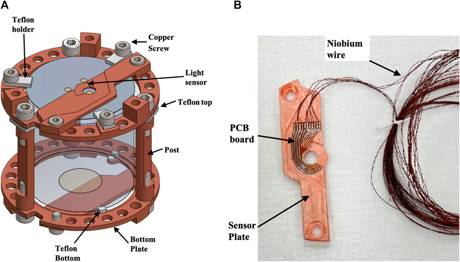
Figure 1. A schematic figure of a detector module (A) and a photo of a real detector sensor plate (B) of the AMoRE-II experiment. Crystals are used with diameters of both 5 and 6 cm, with module dimensions adjusted accordingly.
Table 1. HPGe assay results for internal materials.
Table 2. Concentrations of 238U and 232Th in the internal materials, determined by ICP-MS analysis, or by NAA where indicated.
The AMoRE-II experiment uses two types of scintillating crystals, CaMoO4 and Li2MoO4. The internal contamination of the CaMoO4 crystals is characterized by the AMoRE-Pilot and AMoRE-I detectors [19, 20]. Before growing the Li2MoO4 crystals, precursor materials (molybdenum trioxide and lithium carbonate powders) are tested to confirm the AMoRE-II purity requirements for precursors [16, 21]. The bulk contamination levels for ingots grown using preliminary purified and non-purified precursors are shown in Table 1. The internal contamination of all the enriched Li2MoO4 crystals grown from 2020 to 2023 by CUP and NIIC has been measured by ICP-MS to monitor the crystal production routine. For each crystal, about 1 g of sample is cut from the upper and bottom of the ingot after cutting the crystals and assayed with ICP-MS. For all recently tested 200 crystals, 238U and 232Th are found to be less than 10 pg/g.
After cutting the crystals from the original ingots, the crystal surfaces are lapped and polished. The SiO2 abrasive powder is selected as the cleanest material for surface conditioning. The Admatechs SO-E (low-alpha beam grade) type powder is used. Powders with 8 μm and 1.5 μm particle sizes are used for lapping and final polishing of the crystal surface, respectively. Since lithium molybdate is highly hygroscopic, protection measures are required to save the crystal surface from moisture damage. The Lubriplate low-viscosity non-detergent mineral oil is selected as a lubricant to protect the crystal surfaces from moisture and smooth the polishing. The Ciegal 7355-000FE polyurethane polishing pads are used for buffing at the final polishing step.
We measured NOSV and OFE copper from Aurubis company in Germany and OFE copper from Mitsubishi company in Japan. Bulk contamination of the copper was studied and reported in Ref. [22]. For convenience, results are presented here in Table 2. Samples of about 1 cm3 were cut from the initially received stock plates. The cubic samples were etched twice in strong nitric acid with sonication to remove the contaminated surface. Cleaned samples were reconstituted within strong nitric acid, and Th and U were extracted with a 2 mL UTEVA resin cartridge. The extraction efficiency was controlled by analyzing a sample spiked with a known amount of Th and U standard solution. Bulk contamination levels of 232Th and 238U in the NOSV-Cu stock plate purchased in 2014 were found to be unacceptable for AMoRE-II, while levels in the plates purchased later in 2018 and 2021 were found to be suitable use as crystal holder material. Holder units, except for the screws, were machined from the original copper plates of NOSV-Cu purchased in 2018 and 2021. The screws were machined from the 2018 OFE-Cu. Each holder unit was degreased with kerosene and ethanol, and then a surface layer of about 1 μm was removed by etching with sonication in 5% nitric acid solution. The etched surface of the copper units was passivized and rinsed with deionized water.
After the surface etching procedure, the sensor plates, posts, and screws were measured with ICP-MS. Metal from the bodies of the pieces was digested in nitric acid and moved to the extraction procedure. Analysis of the sensor plates with simple flat surfaces showed efficient Th and U removal with this cleaning procedure. Each post has two screw threads, which, due to the machining process, may have more deeply-embedded contamination. The screws, like the posts, could not be etched deeper than 1 μm without compromising their functional integrity. The screws, which were made of OFE-Cu, showed about 10 pg/g of 232Th and 2 pg/g of 238U, while the bulk concentration of the stock OFE-Cu was about 1 pg/g for both.
While ICP-MS proved suitable levels for 232Th and 238U, proving sufficiently low levels of 226Ra and 228Th is a different challenge. To this end, we prepared a large sample of the 2014 NOSV copper reported in Ref. [22] to be counted on the CAGe array detector. The total sample mass was 145 kg, prepared as eleven plates, each 2 cm thick, with one 30 cm × 30 cm plate placed horizontally between the array halves, and the others (19.6 cm × 35 cm and 19.6 cm × 38 cm) placed on edge around the four sides of the detector elements. Before installation, the plates were all cleaned by scrubbing with Alconox, by a weak nitric, etch, and finally by rinsing in DI water. A supporter was designed to fill the space around the bottom array cryostat, thus supporting the outer copper plates at a height level with the bases of the cans housing the lower array detector elements. The supporter was machined from low-activity cast acrylic and made in four parts for assembly around the detector. Figure 2 shows the arrangement of the copper in the CAGe detector chamber with the acrylic supporter. The sample was counted for about 83 days with Rn-free air supplied to the room. Background data was taken in a similar condition for about 32 days with the supporter in place but with the sample removed.
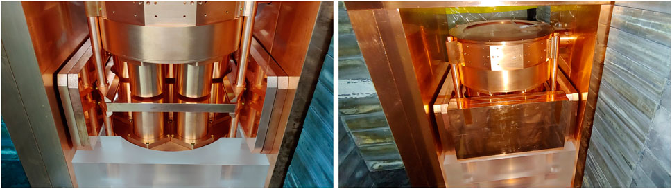
Figure 2. NOSV 2014 copper sample plates, 145.5 kg in total, installed in the CAGe detector chamber. In the left image, the acrylic base supporter supports four sample plates, two on each side of the detector. A central plate rests on the sample supporter blades, which support it horizontally between the upper and lower halves of the detector array. The right image shows the final three vertical plates installed on the near side, with three more out of view on the far side.
For large samples, on any of the HPGe detectors, we often simulate potential background shielding of the sample [11, 12] and use the difference between the full background and the potentially shielded background as a systematic error. To be specific, backgrounds originating from sources near to or within the detector will not be shielded by the sample, while backgrounds originating from sources blocked by the sample could be significantly shielded. Since we do not know the distribution of background sources, this represents a systematic error. The simulation allows optional selection of a sample, as well as one of any pre-defined volumes for generating background decays, both as run-time configurations to the program. A batch submission script runs simulation jobs for events in the sample, in the background generation volume with the sample in place, and in the background generation volume without the sample, for any selected isotopes. A batch analysis determines detection efficiency for decays in the sample and compares background decay spectra with and without the sample to quantify the background-shielding effect of the sample. For the CAGe, we simulate background decays from the vicinity of two opposing copper shielding walls, specifically between the door shielding and the thin Vikuiti window sheets that seal the two detector openings. These volumes represent a realistic location for radon decays, and also represent a region where backgrounds are expected to be maximally shielded by the sample. In the case of the 2014 NOSV measurement, because of the unusually high density and thickness of the sample, the backgrounds from this simulation were attenuated to 20% of their un-shielded rates, or less, depending on the gamma energy. Since we do not know the true source of the backgrounds, or if they are shielded at all, we perform the analysis with full background subtraction, and again with subtraction of the attenuated background rates, treating the difference as a systematic error. For any decay sub-chain, if either scenario is consistent with zero, a 90% limit is derived from the higher result. In this case, because the potential background shielding is nearly absolute, the procedure is nearly equivalent to deriving upper limits from the sample data alone.
Peak rates from 228Th, 228Ac, and 40K were conclusively positive but consistent with measured background levels. The 226Ra rates in the sample data were slightly below the background level. Results from the analysis are shown in Table 1. However, we note that the striking similarity between the sample and background rates, particularly in the 40K and 232Th chains, leaves the likely possibility that the background sources are primarily internal to the detector and not shielded by the sample, such that full background subtraction would be appropriate. In particular, it was previously reported that o-rings in the detector construction contain high levels of 40K [15]. A traditional background subtraction analysis, assuming no background shielding, implies stronger limits in the range of 19–26 μBq/kg for 228Th, 228Ac, and 226Ra, and <200 μBq/kg for 40K, as limited by counting statistics, close to limits for earlier production batches of NOSV copper previously reported in Refs. [23, 24]. The 226Ra limits without background subtraction meet the requirements for AMoRE-II, while the 228Th results are also limits, but are close to our goals only if full background subtraction is assumed.
As copper is a material of particularly general interest for low-background experiments, in addition to the tabulated results, we report limits of <44 μBq/kg for 235U, <690 μBq/kg for 231Pa, <32 μBq/kg for 227Ac, and <330 μBq/kg for 234Th. To handle interferences, particularly for 231Pa and 223Ra, analysis was performed using an updated version of GDFIT [25], with a coupled fit of activities to the entire spectrum, where peak rates were modelled by the fitted activities and by efficiencies, branching rations, and intensities, with constrained background contributions to each peak. In the 235U chain, since the measurement was performed many months after production of the material, 227Ac was assumed to be in decay equilibrium with 223Ra and its daughters.
This measurement was prepared before ICP-MS measurements determined that the 238U and 232Th concentrations in the 2014 NOSV batch were not suitable for AMoRE. As reported in Ref. [22], the 232Th levels measured in the 2021 NOSV copper used for AMoRE-II were about 17 times lower than the levels in the 2014 copper measured on the CAGe. The combination of low 226Ra, 228Ra, and 228Th levels in the 2014 copper, and greatly reduced 232Th levels in the 2021 copper give reason for optimism that the 228Ra and 228Th activities in the 2021 copper may be significantly below the obtained limits.
In addition to the CAGe measurement of the 2014 NOSV copper, samples of the 2016 and 2021 NOSV coppers were assayed with the CC1 and CC2 100% HPGe detector. The results for all activities in the 238U, 232Th, and 40K chains were limits for both, although with much worse sensitivities.
The detector crystals are cooled to low temperature via heat conduction through the copper holders to the thermal bath. However, the thermal conductivity between the crystals and the thermal bath should be low since the athermal phonons should be collected efficiently by the phonon collector. Therefore, the crystals are mechanically connected to the copper holders by small pieces of insulating PTFE. Specifically, the parts are machined from a product sold by the Maagtechnic company, listed as “ERIFLON Plastic plate PTFE pure virgin white,” and sold in various thicknesses.
ICP-MS measurement of PTFE and other fluorocarbon plastics is challenging because digestion requires particularly hazardous chemicals. However, as these have been found to be very clean materials, a number of high-sensitivity measurements have been performed [26–31]. Maagtechnic PTFE was selected largely because measurements have already been performed for other rare-event experiments and reported in Refs. [27, 29]. Both references report only limits for a range of naturally occurring radioactivies, with Ref. [29] reporting less than about 63 μBq/kg or better for all of 226Ra, 228Ra, and 228Th from direct HPGe assay and reporting corroborating limits inferred from ICP-MS measurements. At CUP, we prepared samples of the material (purchased as plates from the Eriflon product line) for measurement using neutron activation analysis (NAA). Samples were prepared as discs of 10 mm diameter by 5 mm height, machined from 15 mm stock, and cleaned along with irradiation vials via a procedure using ultrasonic cleaning and nitric acid etching. A total sample mass of 3.4 g was analyzed with NAA by the Korea Atomic Energy Research Institute using 4 h of sample irradiation at the HANARO reactor operated at a power of 15 MW. The resulting limits were <200 pg/g and <100 pg/g for 232Th and 238U, respectively, as tabulated in Table 2. This was the first attempt to use NAA at HANARO for sample analysis. Several factors can be optimized in the procedure, including reactor power, sample mass, counting time, and counting delay.
One of the most serious backgrounds to the 0νββ signal is from alpha decays from contaminants on or near the surfaces of the crystals. Because of energy loss in non-sensitive material, the resulting signals can be at any energy from zero to the alpha emission energy. To avoid this continuum of alpha signals, the scintillation from detector events is measured by photon sensors above the crystals. We positioned a Vikuiti reflective film around the sides of the crystals to improve photon transport. About 80 cm2 is required for the 5 cm diameter crystals, and over 110 cm2 is needed for the 6 cm diameter crystals. Since this film directly faces the detectors, it is critical that it has low levels of radioactive contaminants. Both a roll-type and sheet-type film were tested at CUP with a procedural detection limit of about 1 pg/g for 232Th and 238U [22].
The sample decomposition was performed without any preliminary cleaning, as in the real experiment. After a protection cover was peeled off, the Vikuiti film was cut into small pieces of about 0.5 g. Then the samples were ashed step-wise in quartz crucibles using microwave heat. The resulting ash was quantitatively dissolved in nitric acid, and thorium and uranium were directly measured with ICP-MS without any column separation. The roll-type Vikuiti film was found to have two times lower Th concentration and four times lower U concentration than the sheet-type film, and was selected for the detector assembly. Vikuitti is no longer manufactured, but we have enough supplies for AMoRE-II.
Energy depositions in the crystals are read by sensors composed of metallic magnetic calorimeters (MMCs) and superconducting quantum interference devices (SQUIDs). The sensors for each detector module are mounted on a copper sensor plate, with connections wire bonded to a printed circuit board (PCB) which is attached to the same plate, as shown in Figure 1. This arrangement serves to prevent strain on the connection to the sensors. Superconducting niobium wires from Supercon Inc. connect from this PCB to a connection board at the mixing chamber, above the lead shielding. This connection is about 2 m long. From there, bundled NOMEX ribbon cables make the connection to a junction box at room temperature. Ceramic or plastic PCBs have high radioactivity. The selected PCB board (sometimes called a flex cable) is model HGLS-D211EM made by Hanwha L&C, having copper foil (35 μm thick) glued with adhesive (10 μm thick) to both sides of a polyimide film (25 μm thick). One side is etched to make the circuit. The other side of the PCB board is attached to the copper plate by lead-tin solder. The PCBs were measured by ICP-MS and also by HPGe counting. The sample for HPGe counting had a mass of 1.16 kg and was measured with the detector for 20 days. This gave upper limits of 1.08 mBq/kg for 214Bi and 1.07 mBq/kg for 228Th. The ICP-MS results were 893 ± 90 pg/g and <1.2 pg/g for U and Th, respectively.
The MMC and SQUID were attached to the copper sensor plate by Loctite brand Stycast glue. Both Stycast 2850 and Stycast 1266 were assayed with HPGe. We used Stycast 1266 for AMoRE-II as Stycast 2850 had high radioactivity. Stycast 1266 has two parts: resin and hardener. Both were measured individually, and the measurements gave upper limits, as shown in Table 1.
We use lead-tin solder to attach the PCB to the copper sensor plate and to attach the niobium wires to the PCB. The total mass of solder connecting this board to wires and the plate is nominally about 70 mg per board, and two boards are used (one for heat and one for light) for each detector module. Since the radiopurity of the lead solder is critical, we made this material in one of our chemical labs. The ratio of lead to tin is 6:4. We have measured different grades of tin material from the Alfa Aesar company. We started by measuring their 99.85% purity grade tin powder. The 210Pb activity was observed to be about 500 Bq/kg, which was unacceptable for use in AMoRE-II. Zone-refining purification was implemented to reduce contamination of the lead. With 35 sequential zone melting cycles, the contamination level was still several hundred Bq/kg, so we then tested the tin bead samples with 5N and 6N purity grades from the same company. Upper limits of 2.1 Bq/kg for 210Pb were found for both products using HPGe, and a 50 pg/g upper limit was found for both 238U and 232Th using ICP-MS. The 5N and 6N products were used for the solder production without any preliminary treatment. To be melted with the tin, lead pieces were cut from bulk plates of ancient lead [32] and were then cleaned with sonication using 10% nitric acid, rinsed with deionized water, and dried.
The low-background AMoRE physics run data is dominated by the 2νββ spectra and has few events in full-energy gamma peaks. For calibration, we need to have a steady source of events with well-defined energy and shape. For this purpose, we inject a thermal signal by flowing a small current with a resistance. The heater is made of a silicon wafer and is attached to the crystal surface by Araldite glue.
The cryostat is under vacuum, and cooling is provided by pulsed tube refrigeration and a dilution refrigeration unit. The dilution refrigerator and the cryostat are made by the Leiden company in the Netherlands. The overview of the cryostat is shown in Figure 3. The system contains six consecutively-colder vacuum-separated cylindrical containers, with the outermost vacuum can (OVC) at room temperature. The cylinders with attached bottom plates are referred to as “cans”, and a connected series of lids, or cooling plates, closes the top of each respective layer.

Figure 3. A schematic figure of the cryostat of the AMoRE-II experiment.
The lowest cooling plate houses the mixing chamber and is connected to the upper copper plate of the detector assembly by soft copper braids. The detector assembly consists of inner lead shielding, superconducting magnetic field shielding, and the towers of crystal detectors. The mass of the detector assembly is about 3.1 tonnes. The inner lead shielding is 26 cm thick, with 25 cm of low radioactivity lead, and 1 cm of ancient lead. The upper (outer) 25 cm of lead shielding is composed of five layers of 5 cm thick lead bricks, and the lower (inner) 1 cm of lead shielding is made in a disk shape.
Since we have 26 cm of lead shielding just over the detector assembly, the constraints on the radioactivity of the materials in the cryostat system are not strong. The G11 supporting rods connecting the cooling plates are some of the highest sources of radioactivity in the cryostat and account for a background contribution of 5 × 10⁻⁷ ckky in the ROI. Other materials over the mixing chamber, including the supporting Kevlar strings, will not contribute significant backgrounds.
The outer vacuum chamber is made of 304-grade stainless steel. It is divided into two cylinders coupled with stainless screws M8. Therefore, it has three flanges in total. The flanges are made of stainless steel plate, bent and welded to make a hoop. The welding of flange ends to form the hoops is done with flux core welding rods (K-308LT from KISWEL Korea Welding company) with radioactivities found to be high, 48.4 ± 2.4 Bq/kg for 226Ra and 20.6 ± 1.0 Bq/kg for 228Th. The flux inside the welding rods may contribute strongly to the radioactivity of the rods, but the flux is not fully incorporated into the weld. It is thus necessary to evaluate the radioactivity contamination of the welded part after welding. We made a welding part similar to the flange structure by welding stainless steel with flux core welding with a similar weld geometry and applying a similar amount of weld material. We measured the resulting 1.77 kg sample part with the HPGe detector, and found activities of 16.4 ± 1.6 mBq/kg for 226Ra and 12.9 ± 1.5 mBq/kg for 228Th. The hoop-shaped flanges are welded to the cylinders with TIG welding using AWS AS.9 ER308L rod from Hyundai welding company. The cylinders themselves are also formed with a TIG-welded seam. Each part of the OVC is cleaned by electropolishing.
There are four copper plates and cans from outside to inside the plates at temperatures of 50 K and 4 K, the dilution refrigerator still, and the 50 mK stage. The inner vacuum can (IVC) is connected to the 4 K plate. The copper cans are made by bending the OFE copper plates of various thicknesses supplied by the Aurubis company. The size and thickness of the cans are listed in Table 3. The radioactivity is measured and is shown in Table 4. All cans are divided into two cylinders coupled with stainless screws M8 of 16 mm diameter. The surfaces were cleaned with 5% nitric acid before assembling. The welding is done by e-beam welding.
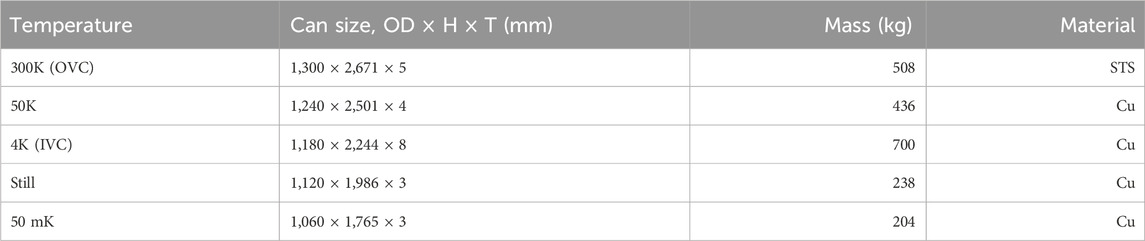
Table 3. The cans of the cryostat and dilution refrigerator.
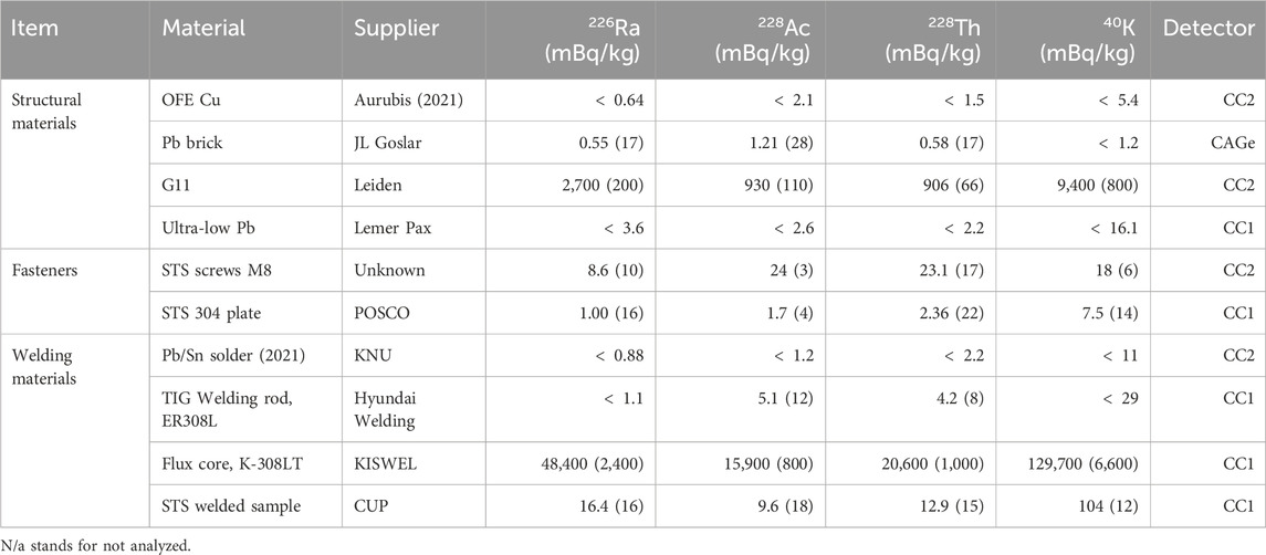
Table 4. HPGe assay results for cryostat materials.
The inner lead is 26 cm thick, and the total mass of the shielding is about two tonnes. The outer 25 cm thick lead consists of lead bricks supplied by JL Goslar Gmbh in Germany. The lead bricks are in the size of 5 cm × 10 cm × 20 cm. The radioactivities of these bricks were measured with the CAGe [33]. The bricks were first sliced with a water jet cutting machine into 5 mm thick plates. The plates were cleaned with 10% nitric acids for 20 min. Then, six plates were located between the top and bottom arrays of the CAGe. This setup has a sensitivity to 226Ra of around 0.1 mBq/kg. The Goslar bricks samples were found to have 226Ra activity of 0.55 ± 0.17 mBq/kg and 228Th activity of 0.58 ± 0.17 mBq/kg. The 210Pb content was 30 ± 1 Bq/kg. The ancient lead, forming the 1 cm inner layer and supplied by the Lemer Pax company, had 210Pb activity of only 100 ± 10 mBq/kg. As this layer sits inside the Goslar lead, it shields the detector from the higher 210Pb activity of the Goslar bricks. To increase the thermal conductivity between the mixing chamber plate and the detector assembly structure via the lead shielding, the lead bricks are divided into two sections and pressed by M20 (12 each) and M10 (9 each) copper rod-screws, with copper sheets between the lead blocks.
To remove the noise produced by the alternating and static magnetic fields in the detector environment, we installed the lead superconducting magnetic shield surrounding the detector towers. The lead sheet is made with ancient lead ingot imported from the Lemer Pax company in France. The ingot was melted to make a block about 1 cm thick and rolled with a drum to make plates with a thickness of about a millimeter. A cylindrical copper structure is made with a copper frame of 3 mm thickness and assembled with brass screws. The rolled lead sheets are welded to the structure with ultra-low radioactive lead-tin solder. The manufacturing process contaminated the surface of the lead sheets. A sample of 10 cm × 10 cm lead sheet is measured with the alpha counter, and the surface alpha emission rate was 2.53 ± 0.15 × 10⁻²/cm2/hour after 20 min in 10% nitric acid. Further cleaning with 40 min in 10% nitric acid reduced the rate to 1.25 ± 0.07 × 10⁻²/cm2/hour. The whole structure, including the lead sheets, is submerged in 10% nitric acid to remove surface contamination during the manufacturing processes. The superconducting shielding structure will be attached to the copper plate at the bottom of the inner lead shielding.
The shielding structure is shown in Figure 4. The primary passive gamma shielding is provided on four sides and the bottom by a 25 cm thick lead wall surrounding the cryostat. The corresponding top shielding is provided by the 26 cm of lead at the top of the detector assembly, within the cryostat, as described in Section 4. The wall is surrounded by 1 cm thick borated-rubber [34] sheets that capture thermal neutrons and reduce the background produced by neutron reactions, particularly on copper and lead. This layer is then covered by 70 cm thick polyethylene for fast neutron attenuation, with the muon veto detectors forming the outermost layers. The sides and bottom of the structure are covered by plastic scintillator muon detectors (PSMDs). Each PSMD module is made with two plates of extruded plastic scintillator read by wavelength-shifting fibers attached to each and separated by a gap of 2 cm. The fibers are read by two SiPM sensors for each plate. This entire structure, including the lead, polyethylene, and scintillator detectors, is divided into two halves that sit on a motor-driven system, allowing them to separate for access to the cryostat. The top of the cryostat is covered by a water Cherenkov muon detector (WCMD) with 48 PMTs, including a mix of eight-inch (R5912) and ten-inch (R7081) PMTs. The lead shielding efficiently blocks gamma emissions from contaminants in construction materials, so radioactive contaminants in the mentioned materials outside of the lead contribute negligibly to the detector backgrounds. Below, we describe the shielding components from the lead wall inward.
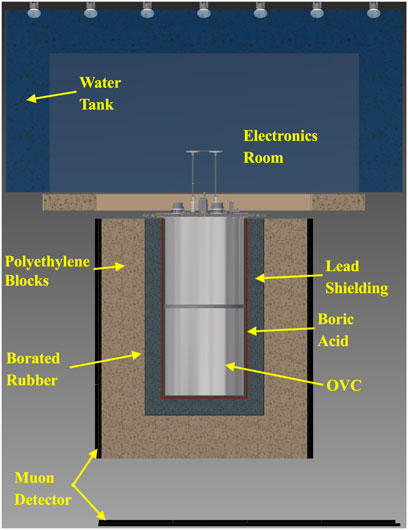
Figure 4. A schematic figure of the shielding structure of the AMoRE-II experiment.
The outer lead shielding consists of 25 cm thick walls that surround the cryostat on five sides, with a total mass of about 60 tons. The outer 20 cm thick lead is made of normal lead supplied by a Korean company. It consists of lead bricks with dimensions of 5 cm × 10 cm × 20 cm.
As described in Section 4.3, we have assayed two batches of lead bricks with the CAGe detector at Y2L. The average radioactivities of these bricks used for the outer 20 cm of shielding are 0.38 ± 0.16 mBq/kg for 226Ra and <0.25 mBq/kg for 228Th. The inner 5 cm of shielding was filled with Boliden lead that was dismantled from the shielding of the KIMS experiment at Y2L. The average radioactivities measured with the CAGe detector are 0.48 ± 0.12 mBq/kg for 226Ra and 0.45 ± 0.11 mBq/kg for 228Th. This is similar to the activities of the JL Goslar lead as reported in Section 4.3. More details on lead measurements will be reported [33]. Since the 0.5 mBq/kg contamination level of 226Ra is about two times higher than the AMoRE-II requirement of an individual item, we will exchange this inner 5 cm of lead with lower background lead before we run the full-scale phase of the AMoRE-II experiment.
We considered placing a few centimeters thickness of additional copper inside the lead shielding to reduce the gamma rays from Bremsstrahlung produced by the decay of 210Pb in the lead shield. However, the simulation shows that even with the neutron shielding layers described here, the background could increase due to thermal neutron capture in the copper plates.
Boron is a very effective material for absorbing thermal neutrons. The thermal neutrons are hazardous to the 0νββ experiment by way of generating high energy gammas from neutron capture reactions in the shielding materials. The effective cross-section of thermal neutrons in copper, iron, and lead are 3.78, 2.75, and 0.17 barn. We may put a few centimeter-thick additional copper layer inside the lead shielding to reduce the 210Pb Bremsstrahlung gamma rays, but the simulation shows it could increase the background due to the thermal neutron capture in the copper plates. Therefore, we try to minimize the copper or iron inside the lead shielding. To minimize the thermal neutron contribution, we placed acrylic boxes containing ultra-pure boric acid powder. The boxes are 500 mm × 500 mm × 10 mm in size, with a wall thickness of 1 mm, so the boric acid is 8 mm thick. These boxes are attached to the lead shielding structure. Since the boric acid is inside the lead shielding, there are limits on its allowable radioactivity levels. We have measured the radioactivity levels of various grades of commercially available boric acid, as shown in Table 5. The radiopurity of boric acid of 99.99% purity supplied by Alpha Aesar company was assayed by HPGe counting with resulting activities of <0.46 mBq/kg for 226Ra and <0.5 mBq/kg for 228Th, though it has 97.9 ± 8.0 mBq/kg for 40K. Another satisfactory boric acid powder, the one which will be used for AMoRE-II, is the 99.5% purity grade supplied by KANTO company with <1.4 mBq/kg for 226Ra and <0.95 mBq/kg for 228Th as shown in Table 5.

Table 5. HPGe assay results for shielding materials.
Since the lead shielding structure has a square cross-sectional footprint, and the cryostat cans are circular, there is a sizable volume of air inside the lead shielding (and inside the boric acid layer). We will surround the shielding structure with a vinyl curtain and flush the interior by injecting a constant flow of Rn-free air with an estimated maximum Rn level in the air of about 5 Bq/m3. At the same time, we will insert urethane balloons filled with nitrogen gas to fill the four corners. This further reduces the Rn level within the balloons and reduces the remaining flushing volume in the tent for more efficient removal of outside air from the tent. Two balloons made of urethane film will be installed inside the lead shielding for each half of the shielding structure. After 10 days of installing the balloons, the activity of 214Bi inside the balloons should be less than 1 mBq in total if no radon penetrates the Urethane film. Two different film samples were assayed with an HPGe detector and found to have less than 1–2 mBq/kg for 226Ra and less than 1 mBq/kg for 228Th, implying a total activity level of less than 50 mBq for this film for all balloons combined.
The volume between the OVC and outer lead shielding is mainly filled by the nitrogen balloon, but some air remains outside of the balloon. The average radon level for the whole volume, including the air balloon, must be below 0.3 Bq/m3. The air in the balloons is expected to have negligible levels of radon activity. Therefore, the requirement for the remaining air is relaxed by a ratio of the total volume to the volume not filled by balloons.
To calibrate the energy and detector response, we will irradiate the detector with gammas emitted from a 232Th source. In particular, the 2614 keV gamma is useful since its energy is near the 0νββ Q-value, and since it penetrates the shielding better than low-energy gammas. The source will be attached outside of the OVC cans. The source material is ThO2 powder with 602 Bq/kg of 228Th activity. The powder is mixed with silicone oil, injected inside a Urethane tube of 8 mm diameter, and cured at room temperature for about 24 h to be a flexible solid tube. The source tube is about 8.5 m long, looping the OVC two times, and can be moved within a tube with a larger diameter of 20 mm. A system of two driving motors located in the electronics room over the cryostat will position the source at different locations for calibration. Since the outer tube is fixed outside the OVC, the radioactivity of the tube will be assayed by the HPGe detector before installation to the OVC.
We have studied the radioactivity of the materials used in the AMoRE-II experiment, where the presented design has already been iterated to reflect the results. We used equipment for ICP-MS, alpha counting, HPGe detection, and NAA to estimate the radioactivity. For HPGe measurements, we have tried to lower the upper limits of the samples by increasing the sample mass and, in some cases, by using the high-efficiency CAGe array detector system. The actual background level from all the components studied in this paper is estimated with Monte Carlo simulations that will be reported separately. These studies show that the experiment would benefit from an upgrade to improve the radiopurity of the inner 5 cm of the 25 cm thick primary passive shielding lead, used to shield gammas from the surrounding environment. We are considering plans to replace this with a lower-activity selection of lead. All the other materials were confirmed to satisfy the requirements for the AMoRE-II experiment to reach a background level of less than 1 × 10⁻⁴ ckky.
The original contributions presented in the study are included in the article/supplementary material, further inquiries can be directed to the corresponding authors.
AA: Writing–review and editing. VA: Writing–review and editing. PA: Writing–review and editing. HB: Writing–review and editing. JB: Writing–review and editing. BB: Writing–review and editing. RB: Writing–review and editing. KB: Writing–review and editing. OB: Writing–review and editing. CB: Writing–review and editing. NC: Writing–review and editing. MC: Writing–review and editing. JCo: Writing–review and editing, Formal Analysis. SChi: Writing–review and editing. SChu: Writing–review and editing. JCu: Writing–review and editing. FD: Writing–review and editing. MD: Writing–review andediting. DD: Writing–review and editing. CE: Writing–review and editing. AF: Writing–review and editing. AGa: Writing–review and editing. LG: Writing–review and editing. YG: Writing–review and editing. AGe: Writing–review and editing. OG: Formal Analysis, Validation, Writing–original draft, Writing–review and editing. VDG: Writing–review and editing. VIG: Writing–review and editing. CH: Writing–review and editing, Software. DHa: Writing–review and editing. EH: Writing–review and editing. DHw: Writing–review and editing. EJ: Software, Writing–review and editing. JJ: Writing–review and editing. HJ: Writing–review and editing. JK: Writing–review and editing. CK: Resources, Visualization, Writing–review and editing. WGK: Writing–review and editing. VKa: Writing–review and editing. SKe: Writing–review and editing. AK: Writing–review and editing. SKh: Writing–review and editing. DYK: Writing–review and editing. GK: Writing–review and editing. HBK: Writing–review and editing. HJK: Writing–review and editing. HJK: Writing–review and editing, Conceptualization, Project administration. HLK: Writing–review and editing. HSK: Writing–review and editing. MK: Writing–review and editing. SCK: Writing–review and editing. SKK: Writing–review and editing. SRK: Writing–review and editing. WTK: Writing–review and editing. YDK: Conceptualization, Project administration, Writing–review and editing. YHK: Writing–review and editing, Conceptualization, Project administration. KK: Writing–review and editing. YJK: Writing–review and editing. VKy: Writing–review and editing. VKn: Writing–review and editing. VKm: Writing–review and editing. DHK: Writing–review and editing. CL: Writing–review and editing. DYL: Writing–review and editing. EL: Formal Analysis, Validation, Writing–original draft, Writing–review and editing. HJL: Writing–review and editing, Resources, Visualization. HLe: Writing–review and editing. JL: Writing–review and editing, Project administration. JYL: Writing–review and editing. KL: Writing–review and editing. MHL: Writing–review and editing. MKL: Writing–review and editing. SL: Writing–review and editing. YL: Writing–review and editing. DSL: Writing–review and editing, Formal Analysis, Validation, Writing–original draft. HLi: Writing–review and editing. BM: Writing–review and editing. EM: Writing–review and editing. PN: Writing–review and editing. YO: Writing–review and editing. SO: Writing–review and editing. SIP: Writing–review and editing. HKP: Writing–review and editing. HSP: Writing–review and editing. KP: Writing–review and editing. SYP: Writing–review and editing, Formal Analysis. OP: Writing–review and editing. HP: Writing–review and editing. SR: Writing–review and editing. SSR: Writing–review and editing. GR: Writing–review and editing. MS: Writing–review and editing. JSe: Writing–review editing, Formal Analysis. KSe: Writing–review and editing. BS: Writing–review and editing. KSh: Writing–review and editing. VS: Writing–review and editing. KSi: Writing–review and editing. JSo: Writing–review and editing. NVS: Writing–review and editing. JKS: Writing–review and editing. JWS: Writing–review and editing. NS: Writing–review and editing. VT: Writing–review and editing. RW: Writing–review and editing. KW: Writing–review and editing. HY: Writing–review and editing. YY: Writing–review and editing. QY: Writing–review and editing.
Abdul Wali Khan University Mardan, Mardan, Pakistan; Ajou University, Suweon, Republic of Korea; Baksan Neutrino Observatory, Institute for Nuclear Research (RAS), Moscow, Russia; Bandung Institute of Technology, Bandung, Indonesia; Center for Underground Physics, Institute for Basic Science, Daejeon, Republic of Korea; Chung-Ang University, Seoul, Republic of Korea; Department of Physics and Astronomy, Kirchhoff-Institute for Physics, Heidelberg University, Heidelberg, Germany; Florida Institute of Technology, Melbourne, FL, United States; Fomos Material, Moscow, Russia; Indian Institute of Science (IISc), Bangalore, India; Institute for Nuclear Research (RAS), Moscow, Russia; Institute for Nuclear Research, National Academy of Sciences of Ukraine (NAS Ukraine), Kyiv, Ukraine; Kohat University of Science and Technology, Kohat, Pakistan; Korea Research Institute of Standards and Science, Daejeon, Republic of Korea; Korea University, Sejong, Republic of Korea; Kyungpook National University, Daegu, Republic of Korea; Nakhon Pathom Rajabhat University, Nakhon Pathom, Thailand; National Research Nuclear University MEPhI, Moscow, Russia; Nikolaev Institute of Inorganic Chemistry (RAS), Novosibirsk, Russia; Padang State University, Padang, Indonesia; Physical-Technical Federal Institute, Braunschweig, Germany; Sejong University, Seoul, Republic of Korea; Seoul National University, Seoul, Republic of Korea; Seoul National University Hospital, Seoul, Republic of Korea; Shiv Nadar University, Greater Noida, India; Soongsil University, Seoul, Republic of Korea; State University of Malang, Malang, Indonesia; The University of Tokyo, Bunkyo, Japan; Tsinghua University, Beijing, China; University of Mataram, Mataram, Indonesia; University of Science and Technology, Daejeon, Republic of Korea; V. N. Karazin Kharkiv National University, Kharkiv, Ukraine.
The authors declare that financial support was received for the research, authorship, and/or publication of this article. This research was funded by the Institute for Basic Science (Korea) under project codes IBS-R016-D1 and IBS-R016-A2. It is also supported by the Ministry of Science and Higher Education of the Russian Federation (N121031700314-5), the MEPhI Program Priority 2030, the National Research Foundation of Korea (NRF-2021R1I1A3041453, NRF-2021R1A2C1013761 NRF-2018K1A3A1A13087769), and the National Research Facilities and Equipment Center (NFEC) of Korea (No. 2019R1A6C1010027).
The authors acknowledge Dr. Boyoung Han at KAERI for helping with the NAA measurements of the plastic samples. These acknowledgments are not to be interpreted as an endorsement of any statement made by any of our institutes, funding agencies, governments, or their representatives.
Author VA and OB were employed by the company Fomos Material.
The remaining authors declare that the research was conducted in the absence of any commercial or financial relationships that could be construed as a potential conflict of interest.
All claims expressed in this article are solely those of the authors and do not necessarily represent those of their affiliated organizations, or those of the publisher, the editors and the reviewers. Any product that may be evaluated in this article, or claim that may be made by its manufacturer, is not guaranteed or endorsed by the publisher.
1. Jones BJP. Theoretical advanced study institute in elementary particle physics: the obscure universe: neutrinos and other dark matters (2021).
2. Giunti C, Kim CW. Fundamentals of neutrino physics and astrophysics, 710. Oxford, UK: Univ. Pr. (2007). p. 2007.
3. Mohapatra RN, Antusch S, Babu KS, Barenboim G, Chen MC, de Gouvêa A, et al. Theory of neutrinos: a white paper. Rept Prog Phys (2007) 70:1757–867. doi:10.1088/0034-4885/70/11/R02
4. Furry WH. On transition probabilities in double beta-disintegration. Phys Rev (1939) 56:1184–93. doi:10.1103/PhysRev.56.1184
5. Rahaman S, Elomaa VV, Eronen T, Hakala J, Jokinen A, Julin J, et al. Q values of the 76Ge and 100Mo double-beta decays. Phys Lett B (2008) 662:111–6. doi:10.1016/j.physletb.2008.02.047
6. Kim HB, Ha DH, Jeon EJ, Jeon JA, Jo HS, Kang CS, et al. Status and performance of the AMoRE-I experiment on neutrinoless double beta decay. Phys (2022) 209(5-6):962–70. doi:10.1007/s10909-022-02880-z
7. Kim HBAMoRE Collaboration. Result of AMoRE-I Experiment [Conference presentation]. TAUP 2023 (2024). Available from: https://indico.cern.ch/event/1199289/contributions/5445986/
9. Pavan M. CUPID: CUORE upgrade with particle IDentification. J Phys Conf Ser (2020) 1468(1):012210. doi:10.1088/1742-6596/1468/1/012210
10. Kim WT, Kim S, Sharma B, Gileva O, Grigorieva V, Jeon J, et al. Optimization of cryogenic calorimetric detection with lithium molybdate crystals for AMoRE-II experiments. JINST (2022) 17(07):P07034. doi:10.1088/1748-0221/17/07/P07034
11. Lee EK, et al. HPGe measurements of detector material samples and background screening study at Yangyang laboratory. Fall Meeting: Korean Physical Society (2019).
12. Thiesse M, Scovell P, Thompson L Background shielding by dense samples in low-level gamma spectrometry. Appl Radiat Isot (2022) 188:110384. doi:10.1016/j.apradiso.2022.110384
13. Lee EK, Hahn KI, Jeon E, Kang W, Kazalov V, Kim G, et al. Measurements of detector material samples with two HPGe detectors at the YangYang Underground Lab. PoS ICHEP2018 (2019) 809. doi:10.22323/1.340.0809
14. Park SY, Hahn K, Kang W, Kazalov V, Kim G, Kim Y, et al. Detection efficiency calibration for an array of fourteen HPGe detectors. Appl Radiat Isot (2023) 193:110654. doi:10.1016/j.apradiso.2023.110654
15. Leonard DS, Hahn KI, Kang WG, Kazalov V, Kim GW, Kim YD, et al. Development of an array of fourteen HPGe detectors having 70% relative efficiency each. Nucl Instrum Meth (2021) A989:164954. doi:10.1016/j.nima.2020.164954
16. Yeon H, Choe J, Gileva O, Hahn KI, Kang WG, Kim GW, et al. Preparation of low-radioactive high-purity enriched 100MoO3 powder for AMoRE-II experiment. Front Phys (2023) 11:1142136. doi:10.3389/fphy.2023.1142136
17. Ha C, Adhikari G, Adhikari P, Jeon E, Kang W, Kim B, et al. Initial performance of the high sensitivity alpha particle detector at the Yangyang underground laboratory. Nucl Instr Methods Phys Res Section A: Acc Spectrometers, Detectors Associated Equipment (2019) 913:15–9. doi:10.1016/j.nima.2018.09.129
18. Alenkov V, Bae HW, Beyer J, et al. First results from the AMoRE-Pilot neutrinoless double beta decay experiment. Eur Phys J (2019) C79(9):791. doi:10.1140/epjc/s10052-019-7279-1
19. Lee JY, Alenkov V, Ali L, Beyer J, Bibi R, Boiko RS, et al. A study of radioactive contamination of crystals for the AMoRE experiment. IEEE Trans Nucl Sci (2016) 63(2):543–7. doi:10.1109/TNS.2016.2530828
20. Lee JY, Aryal P, Karki S, Kim HJ, Kim SK, Kim YD, et al. A study of 48deplCa100MoO4 scintillation crystals for the AMoRE-I experiment. IEEE Trans Nucl Sci (2018) 65:2041–5. doi:10.1109/TNS.2018.2818332
21. Gileva O, Aryal P, Choe JS, Yena K, Kim Y, et al. Purification of lithium carbonate from radioactive contaminants using a MnO2-based inorganic sorbent. Inorganics (2023) 11:11100410. doi:10.3390/inorganics11100410
22. Gileva O, Choe J, Kim Y, Lee MH, Leonard DS, Shin K, et al. Thorium and uranium trace ICP-MS analysis for AMoRE project. Appl Radiat Isot (2023) 194:110673. doi:10.1016/j.apradiso.2023.110673
23. Laubenstein M, Hult M, Gasparro J, Arnold D, Neumaier S, Heusser G, et al. Low Underground measurements of radioactivity, Appl Radiat Isot 61(2), 167–72. (2004). doi:10.1016/j.apradiso.2004.03.039
24. Laubenstein M, Geusser G. Cosmogenic radionuclides in metals as indicator for sea level exposure history. Appl Rad Isot (2009) 67:750–4. doi:10.1016/j.apradiso.2009.01.029
25. Leonard DS, Auty D, Didberidze T, Gornea R, Grinberg P, MacLellan R, et al. Nuclear instruments and methods in physics research section A: accelerators, spectrometers, detectors and associated equipment , 871, 169–79. (2017). DOI doi:10.1016/j.nima.2017.04.049
26. Leonard DS, et al. Systematic study of trace radioactive impurities in candidate construction materials for EXO-200. Nucl Instrum Meth (2008) 591:490–509. doi:10.1016/j.nima.2008.03.001
27. Aprile E, Arisaka K, Arneodo F, Askin A, Baudis L, Behrens A, et al. Material screening and selection for XENON100. Astroparticle Phys (2011) 35(2):43–9. doi:10.1016/j.astropartphys.2011.06.001
29. Aprile E, Aalbers J, Agostini F, Alfonsi M, Amaro FD, Anthony M, et al. Material radioassay and selection for the XENON1T dark matter experiment. J C (2017) 77(12):890. doi:10.1140/epjc/s10052-017-5329-0
33. Agrawal A, et al. To be submitted to arXiv. Consideration of screen effect in radioassay of high effective atomic number material for AMoRE-II double-beta decay experiment
Keywords: double beta decay, radiopurity, radioassay, ICP-MS, HPGe
Citation: Agrawal A, Alenkov VV, Aryal P, Bae H, Beyer J, Bhandari B, Boiko RS, Boonin K, Buzanov O, Byeon CR, Chanthima N, Cheoun MK, Choe JS, Choi S, Choudhury S, Chung JS, Danevich FA, Djamal M, Drung D, Enss C, Fleischmann A, Gangapshev AM, Gastaldo L, Gavrilyuk YM, Gezhaev AM, Gileva O, Grigorieva VD, Gurentsov VI, Ha C, Ha DH, Ha EJ, Hwang DH, Jeon EJ, Jeon JA, Jo HS, Kaewkhao J, Kang CS, Kang WG, Kazalov VV, Kempf S, Khan A, Khan S, Kim DY, Kim GW, Kim HB, Kim HJ, Kim HJ, Kim HL, Kim HS, Kim MB, Kim SC, Kim SK, Kim SR, Kim WT, Kim YD, Kim YH, Kirdsiri K, Ko YJ, Kobychev VV, Kornoukhov V, Kuzminov VV, Kwon DH, Lee CH, Lee DY, Lee EK, Lee HJ, Lee HS, Lee J, Lee JY, Lee KB, Lee MH, Lee MK, Lee SW, Lee YC, Leonard DS, Lim HS, Mailyan B, Makarov EP, Nyanda P, Oh Y, Olsen SL, Panasenko SI, Park HK, Park HS, Park KS, Park SY, Polischuk OG, Prihtiadi H, Ra S, Ratkevich SS, Rooh G, Sari MB, Seo J, Seo KM, Sharma B, Shin KA, Shlegel VN, Siyeon K, So J, Sokur NV, Son JK, Song JW, Srisittipokakun N, Tretyak VI, Wirawan R, Woo KR, Yeon HJ, Yoon YS and Yue Q (2024) Radioassay of the materials for AMoRE-II experiment. Front. Phys. 12:1362209. doi: 10.3389/fphy.2024.1362209
Received: 27 December 2023; Accepted: 18 March 2024;
Published: 10 June 2024.
Edited by:
Aldo Ianni, Gran Sasso National Laboratory (INFN), ItalyReviewed by:
Manish Sharma, Pacific Northwest National Laboratory (DOE), United StatesCopyright © 2024 AMoRE Collaboration. This is an open-access article distributed under the terms of the Creative Commons Attribution License (CC BY). The use, distribution or reproduction in other forums is permitted, provided the original author(s) and the copyright owner(s) are credited and that the original publication in this journal is cited, in accordance with accepted academic practice. No use, distribution or reproduction is permitted which does not comply with these terms.
*Correspondence: O. Gileva, Z2lsZXZhb2xnYUBpYnMucmUua3I=; E. K. Lee, ZnJlc2hibHVlQGlicy5yZS5rcg==; D. S. Leonard, ZGxlb25hcmRfYXRfaWJzLnJlLmty
†ORCID: A. Agrawal, orcid.org/0000-0001-7740-5637; V. V. Alenkov, orcid.org/0009-0008-8839-0010; P. Aryal, orcid.org/0000-0003-4955-6838; H. Bae, orcid.org/0000-0003-1393-8631; J. Beyer, orcid.org/0000-0001-9343-0728; B. Bhandari, orcid.org/0009-0009-7710-6202; R. S. Boiko, orcid.org/0000-0001-7017-8793; K. Boonin, orcid.org/0000-0003-4757-7926; O. Buzanov, orcid.org/0000-0002-7532-5710; C. R. Byeon, orcid.org/0009-0002-6567-5925; N. Chanthima, orcid.org/0009-0003-7774-8367; M. K. Cheoun, orcid.org/0000-0001-7810-5134; J. S. Choe, orcid.org/0000-0002-8079-2743; S. Choi, orcid.org/0000-0002-9448-969X; S. Choudhury, orcid.org/0000-0002-2080-9689; J. S. Chung, orcid.org/0009-0003-7889-3830; F. A. Danevich, orcid.org/0000-0002-9446-9023; M. Djamal, orcid.org/0000-0002-4698-2949; D. Drung, orcid.org/0000-0003-3984-4940; C. Enss, orcid.org/0009-0004-2330-6982; A. Fleischmann, orcid.org/0000-0002-0218-5059; A. M. Gangapshev, orcid.org/0000-0002-6086-0569; L. Gastaldo, orcid.org/0000-0002-7504-1849; Y. M. Gavrilyuk, orcid.org/0000-0001-6560-5121; A. M. Gezhaev, orcid.org/0009-0006-3966-7007; O. Gileva, orcid.org/0000-0001-8338-6559; V. D. Grigorieva, orcid.org/0000-0002-1341-4726; V. I. Gurentsov, orcid.org/0009-0000-7666-8435; C. Ha, orcid.org/0000-0002-9598-8589; D. H. Ha, orcid.org/0000-0003-3832-4898; E. J. Ha, orcid.org/0009-0009-3589-0705; D. H. Hwang, orcid.org/0009-0002-1848-2442; E. J. Jeon, orcid.org/0000-0001-5942-8907; J. A. Jeon, orcid.org/0000-0002-1737-002X; H. S. Jo, orcid.org/0009-0005-5672-6948; J. Kaewkhao, orcid.org/0000-0003-0623-9007; C. S. Kang, orcid.org/0009-0005-0797-8735; W. G. Kang, orcid.org/0009-0003-4374-937X; V. V. Kazalov, orcid.org/0000-0001-9521-8034; S. Kempf, orcid.org/0000-0002-3303-128X; A. Khan, orcid.org/0000-0001-7046-1601; S. Khan, orcid.org/0000-0002-1326-2814; D. Y. Kim, orcid.org/0009-0002-3417-0334; G. W. Kim, orcid.org/0000-0003-2062-1894; H. B. Kim, orcid.org/0000-0001-7877-4995; H. J. Kim, orcid.org/0000-0002-8265-5283; H. J. Kim, orcid.org/0000-0001-9787-4684; H. L. Kim, orcid.org/0000-0001-9359-559X; H. S. Kim, orcid.org/0000-0002-6543-9191; M. B. Kim, orcid.org/0000-0003-2912-7673; S. C. Kim, orcid.org/0000-0002-0742-7846; S. K. Kim, orcid.org/0000-0002-0013-0775; S. R. Kim, orcid.org/0009-0000-2894-2225; W. T. Kim, orcid.org/0009-0004-6620-3211; Y. D. Kim, orcid.org/0000-0003-2471-8044; Y. H. Kim, orcid.org/0000-0002-8569-6400; K. Kirdsiri, orcid.org/0000-0002-9662-770X; Y. J. Ko, orcid.org/0000-0002-5055-8745; V. V. Kobychev, orcid.org/0000-0003-0030-7451; V. Kornoukhov, orcid.org/0000-0003-4891-4322; V. V. Kuzminov, orcid.org/0000-0002-3630-6592; D. H. Kwon, orcid.org/0009-0008-2401-0752; C. H. Lee, orcid.org/0000-0002-8610-8260; D. Y. Lee, orcid.org/0009-0006-6911-4753; E. K. Lee, orcid.org/0000-0003-4007-3581; H. J. Lee, orcid.org/0009-0003-6834-5902; H. S. Lee, orcid.org/0000-0002-0444-8473; J. Lee, orcid.org/0000-0002-8908-0101; J. Y. Lee, orcid.org/0000-0003-4444-6496; K. B. Lee, orcid.org/0000-0002-5202-2004; M. H. Lee, orcid.org/0000-0002-4082-1677; M. K. Lee, orcid.org/0009-0004-4255-2900; S. W. Lee, orcid.org/0009-0005-6021-9762; Y. C. Lee, orcid.org/0000-0001-9726-005X; D. S. Leonard, orcid.org/0009-0006-7159-4792; H. S. Lim, orcid.org/0009-0004-7996-1628; B. Mailyan, orcid.org/0000-0002-2531-3703; E. P. Makarov, orcid.org/0009-0008-3220-4178; P. Nyanda, orcid.org/0009-0009-2449-3552; Y. Oh, orcid.org/0000-0003-0892-3582; S. L. Olsen, orcid.org/0000-0002-6388-9885; S. I. Panasenko, orcid.org/0000-0002-8512-6491; H. K. Park, orcid.org/0000-0002-6966-1689; H. S. Park, orcid.org/0000-0001-5530-1407; K. S. Park, orcid.org/0009-0006-2039-9655; S. Y. Park, orcid.org/0000-0002-5071-236X; O. G. Polischuk, orcid.org/0000-0002-5373-7802; H. Prihtiadi, orcid.org/0000-0001-9541-8087; S. Ra, orcid.org/0000-0002-3490-7968; S. S. Ratkevich, orcid.org/0000-0003-2839-4956; G. Rooh, orcid.org/0000-0002-7035-4272; M. B. Sari, orcid.org/0000-0002-8380-3997; J. Seo, orcid.org/0000-0001-8016-9233; K. M. Seo, orcid.org/0009-0005-7053-9524; B. Sharma, orcid.org/0009-0002-3043-7177; K. A. Shin, orcid.org/0000-0002-8504-0073; V. N. Shlegel, orcid.org/0000-0002-3571-0147; K. Siyeon, orcid.org/0000-0003-1871-9972; J. So, orcid.org/0000-0002-1388-8526; N. V. Sokur, orcid.org/0000-0002-3372-9557; J. K. Son, orcid.org/0009-0007-6332-3447; J. W. Song, orcid.org/0009-0002-0594-7263; N. Srisittipokakun, orcid.org/0009-0009-1041-4606; V. I. Tretyak, orcid.org/0000-0002-2369-0679; R. Wirawan, orcid.org/0000-0003-4080-1390; K. R. Woo, orcid.org/0000-0003-3916-294X; H. J. Yeon, orcid.org/0009-0000-9414-2963; Y. S. Yoon, orcid.org/0000-0001-7023-699X; Q. Yue, orcid.org/0000-0002-6968-8953
Disclaimer: All claims expressed in this article are solely those of the authors and do not necessarily represent those of their affiliated organizations, or those of the publisher, the editors and the reviewers. Any product that may be evaluated in this article or claim that may be made by its manufacturer is not guaranteed or endorsed by the publisher.
Research integrity at Frontiers
Learn more about the work of our research integrity team to safeguard the quality of each article we publish.