- 1Aerospace Information Research Institute, Chinese Academy of Sciences, Beijing, China
- 2School of Optoelectronics, University of Chinese Academy of Sciences, Beijing, China
For the application of continuously adjustable optical fiber delay lines, a large delay range can increase the instrument’s measurement range. Increased insertion loss of components will reduce the signal-to-noise ratio of the collected signal, ultimately limiting the measurement accuracy of the instrument. In order to take into account both large delay range and low insertion loss in design, a spatial light transmission and fiber coupling model based on scalar diffraction theory was established and the insertion loss was equivalently calculated through the coupling efficiency of the coupling lens. Then, we analyze the impact of optical fiber delay line’s structural parameters and adjustment errors on coupling efficiency. By optimizing lens group parameters and limiting adjustment tolerances, we can reduce the insertion loss of optical fiber delay lines in a large delay range and conduct experimental verification. Considering various influencing factors, we use a lens group with a focal length of 12 mm, achieving a coupling efficiency of no less than 92.7% within the delay range of 0–1 m. This theoretical model provides a new quantitative analysis method for improving the performance of the optical fiber delay line.
1 Introduction
Optical fiber delay line is a component used to control the transmission time of optical signals. It is widely used in optical communication systems and measurement equipment. According to the delay accuracy, it can be divided into incrementally adjustable and continuously adjustable types [1]. According to technical principles, the continuously adjustable type can be divided into spatial optical delay method, fiber grating tuning method, fiber temperature tuning method, optical all-pass filter tuning method and wavelength tuning method based on fiber dispersion [2–6]. Among them, the optical fiber delay line based on the spatial optical delay method has the advantages of small size, light weight, large bandwidth, simple structure and strong anti-interference ability. It is an essential component for optical modulation in the interferometry system. Short coherent laser interference, Mach-Zehnder fiber optic interferometer and optical coherence tomography use optical fiber delay line to match interference position [7–9].
The optical fiber delay line was proposed by Zhao et al. [2] in 2014. It adjusts the length between a pair of lenses through the reflection of a retroreflector prism and uses mechanical structures such as ball screws to achieve delay. This optical fiber delay line’s experimentally measured coupling efficiency is above 80.6% when the delay range is 1–9.6 cm. In 2015, Liang et al. [10] expanded the range of the optical fiber delay line by using multiple retroreflector prisms to refract the optical path. In 2018, Huo et al. completed the system design of the delay line [11] and optimized the mechanical design of the delay line through finite element analysis to improve stability. However, the insertion loss of the optical fiber delay line should also be considered. Higher insertion loss will reduce the laser energy utilization and the detector exposure time needs to be increased to compensate it, resulting in a decrease in the signal-to-noise ratio of the collected signal.
However, the relevant research lacks a quantitative analysis model for the optical fiber delay line’s insertion loss, making it difficult to simultaneously consider both a large delay range and low insertion loss during the design. This paper establishes a scalar diffraction model of spatial light transmission for the optical fiber delay line, proposes a quantitative relationship between insertion loss of the optical fiber delay line and coupling efficiency of coupling lens, and studies the effects of fiber delay line structural parameters and adjustment errors on coupling efficiency of coupling lens. This paper provides a new quantitative analysis method for performance calculation and improvement of the optical fiber delay line.
2 Theoretical model
2.1 The structure of optical fiber delay line
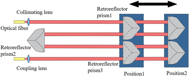
The schematic diagram of the optical fiber delay line is shown in Figure 1. The laser emitted from the fiber becomes spatial light through the collimating lens. Subsequently, it is refracted through the three retroreflector prisms to increases the delay range. Finally, the spatial light is coupled into the fiber through a coupling lens. Among them, the position of retroreflector prism 2 is fixed and the motor controls the movement of retroreflector prisms 1 and 3 simultaneously to change the length of spatial light.
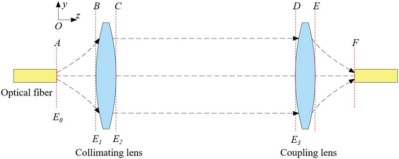
In the system, the energy loss caused by factors such as medium transmission loss and reflection loss is usually minimal and can be ignored [12, 13]. Therefore, we ignore the influence of the retroreflector prism on the optical path. The optical path can be simplified to the structure in Figure 2. The optical path in Figure 2 is used for theoretical analysis and experiments in this article. Insertion loss is the ratio of output power to input power:
In Eq. 1,
Among them,
2.2 Spatial light transmission model
In Figure 2, The spatial light forward transmission model can be simplified to the light field transmission process of “fiber-collimating lens-coupling lens-fiber”.
The ideal output light of a single-mode polarization-maintaining fiber is the
In Eq. 3,
According to the propagation formula of the Gaussian beam, the mode field distribution E1 of the laser reaching the front surface B of the collimating lens can be calculated [16]:
In Eq. 4,
The collimating lens is treated as an ideal thin lens. Its modulation effect on the mode field can be simplified to the phase factor
In Eq. 5,
The propagation of light from the surface C of the collimating lens to the surface D of the coupling lens is a process of free space light, which can be solved using direct integration and angular spectrum diffraction. Direct integration methods (Fresnel diffraction integral, Fraunhofer diffraction integral) obtain approximate solutions when solving inclined planes and have restrictions on the observation plane [18–20]. In order to calculate the impact of the coupling lens’ tilt error on the coupling efficiency accurately, the angular spectrum diffraction method is used for calculation [21]. First, the mode field E2 is converted into a spectrum through the Fourier transform. Then, the spectrum of the front surface of the coupling lens is obtained according to the angular spectrum theory of diffraction. Finally, the mode field E3 is obtained through the inverse Fourier transform:
In Eq. 6,
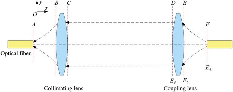
As shown in Figure 3, in order to facilitate the subsequent calculation of coupling efficiency, we assume that the laser propagates backwards and calculate the mode field transmitted backwards from the output fiber end face F to the coupling lens front surface D. In the same way, based on the above derivation, the mode fields E4,E5 and E6 of the reversely transmitted laser at F, E and D can be obtained in sequence.
2.3 Coupling efficiency calculation
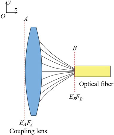
The coupling efficiency of the coupling lens
Among them,
In the optical fiber delay line systems, we also need to consider the impact of other factors on coupling efficiency:
In Eq. 8,
2.4 Factors affecting coupling efficiency
2.4.1 Structural parameters
The optical fiber delay line’s input and output optical ports comprise a collimating lens and a coupling lens. The two are in a conjugate relationship using the same focal length and can be interchanged during use. The distance between the collimating lens and the coupling lens is the delay range of the optical fiber delay line. An optical fiber delay line with a large delay range can increase the measurement range of the interferometry. The delay range designed in this research is 0–1 m. The delay range and the focal length of the lens group jointly affect the intensity and phase of the mode field wavefront. This article calculates the coupling efficiency of lens groups with different focal lengths in the delay range of 0–1 m.
In the delay range of 0–1 m, the relationship between the coupling efficiency and the delay range of lens groups with different focal lengths is shown in Figure 5. At 0 m, the coupling efficiency of different lens groups is the highest. As the delay distance gradually increases, the coupling efficiency gradually decreases. For a lens group with a focal length of 4 mm, the coupling efficiency decreases significantly more than other lens groups because its wavefront is no longer a plane wave after it exceeds the Rayleigh distance. Under the same delay distance, the lens group with the larger focal length has higher coupling efficiency. When the focal length of the lens group increases to 12 mm, the change in coupling efficiency is less than 1% in the delay range of 0–1 m.
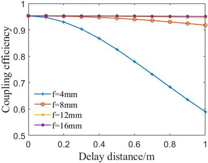
Figure 5. The relationship between coupling efficiency and delay distance of lens groups with different focal lengths.
The larger the focal length of the lens group, the higher the coupling efficiency under the same delay distance. However, when the focal length of the lens group increases, the beam diameter also increases accordingly. Consequently, enormous diameter retroreflector prisms will be use in the system, which is not conducive to the miniaturization of the optical fiber delay line. Finally, a lens group with a focal length of 12 mm was selected. Within the delay range of 0–1 m, the coupling efficiency changes less than 1%.
2.4.2 Adjustment error
The adjustment tolerance of the lens group is an essential basis for the selection of guide rail assembly and retroreflector prism. The lower the sensitivity of the lens group, the easier it is to install and adjust, the lower the accuracy of the adjustment mechanism required and the better the long-term stability. In addition, the collimated light in the optical fiber delay line cannot be completely parallel to the movement path of the retroreflector prism. At the same time, there are comprehensive deflection angle error, overall eccentricity and angular deflection during the movement of the retroreflector prism. According to the relative relationship, these errors can be equal to the eccentricity and tilt error of the coupling lens [23].
In addition, the position error of the fiber end face is also an important influencing factor. Ideally, the fiber end face should be located at the focal plane of the lens. During actual installation and use, the eccentricity, tilt, and defocusing of the fiber end face can also cause changes in the laser wavefront, ultimately leading to a decrease in coupling efficiency. Therefore, the adjustment errors of the lens group and fiber end face position need to be analyzed to guide subsequent design and use.
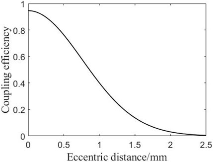
Assuming that the collimating lens is fixed and the coupling lens has a translation in the direction perpendicular to the light. The offset distance between the axis of the coupling lens and the optical axis is the eccentric distance. We calculate the impact of the eccentric distance on the coupling efficiency.
For a pair of 12 mm lens groups at a delay distance of 1 m, the relationship between the coupling efficiency and the overall eccentric distance of the coupling lens is shown in Figure 6. When the coupling lens has no overall eccentricity, the coupling efficiency is 94.6%. When the eccentricity of the coupling lens gradually increases, the coupling efficiency decreases nonlinearly. When the coupling mirror is eccentric by 0.86 mm, the coupling efficiency drops to 50%.
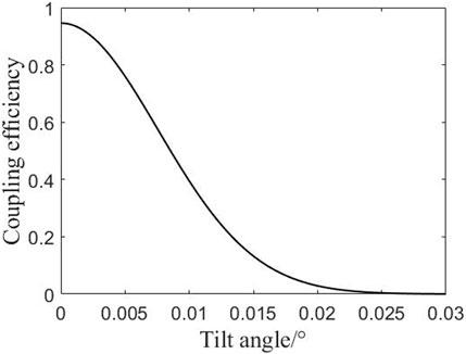
Assuming that the collimating lens is fixed and the coupling lens rotates around the centre of the lens. The angle between the axis of the coupling lens and the optical axis of the incident beam is the tilt angle. We calculate the effect of the tilt on the coupling efficiency.
For a pair of 12 mm lens groups at a delay distance of 1 m, the relationship between the coupling efficiency and the overall tilt angle of the coupling lens is shown in Figure 7. When the coupling lens is not tilted, the coupling efficiency is 94.6%. When the coupling lens is tilted at 0.002°, the coupling efficiency is 91.3%. When the tilt angle increases, the coupling efficiency decreases rapidly. When the coupling lens is tilts at 0.0085°, the coupling efficiency is 50%. When the coupling lens tilts at 0.016°, the coupling efficiency is 10%.
The sensitivity of the coupling lens to tilt error is much greater than the sensitivity to eccentric error. Therefore, the tilt error must be strictly controlled during installation, adjustment and use.
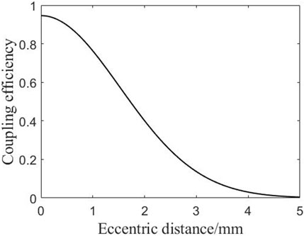
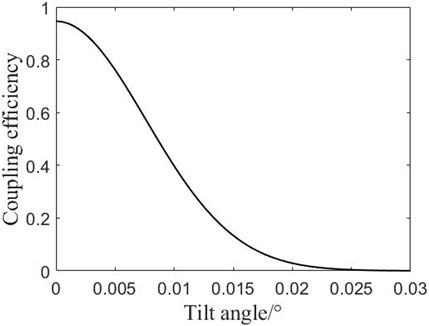
The position error of the fiber end face includes eccentricity, tilt and defocusing. Eccentric distance refers to the distance between the axis of the fiber and the optical axis. The tilt angle refers to the angle between the axis of fiber and the axis of the incident beam when it rotates around the center of the coupling lens. Defocus distance refers to the distance between the fiber end face and the focal point of the coupling lens when the fiber end face is shifted along the optical axis direction. It is negative near the coupling lens and positive away from it. We calculate the relationship between coupling efficiency and fiber end face position error for a pair of lenses with a focal length of 12 mm at a delay distance of 1 m.
The relationship between coupling efficiency and the eccentric distance of the fiber end face is shown in Figure 8. When the fiber end face is not eccentric, the coupling efficiency is highest at 94.6%. When the fiber end face is eccentric by 1 mm, the coupling efficiency is 76.3%. When the eccentricity distance is increased, the coupling efficiency rapidly decreases. When the fiber end face is eccentric by 1.72 mm, the coupling efficiency is 50%. When the fiber end face is eccentric by 3.23 mm, the coupling efficiency is 10%.
The relationship between coupling efficiency and the tilt angle of the fiber end face is shown in Figure 9. When the fiber end face does not rotate, the coupling efficiency is highest at 94.6%. When the fiber end face rotates 0.005°, the coupling efficiency is 76.2%. When the rotation angle is increased, the coupling efficiency rapidly decreases. When the fiber end face rotates by 0.0086°, the coupling efficiency is 50%. When the fiber end face rotates by 0.015°, the coupling efficiency is 13.4%.
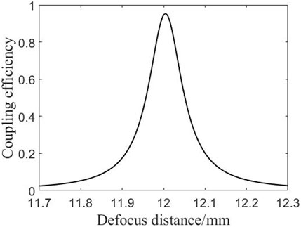
The relationship between coupling efficiency and defocus distance of fiber end face is shown in Figure 10. When the fiber end face is not defocused, the coupling efficiency is close to the highest at 94.6%. When the fiber end face is defocused by 0.004 mm, the coupling efficiency is the highest at 95.3%. Proper defocusing can change the waist position of the laser beam, making the reverse outgoing wavefront more compatible with the incident wavefront. When the defocus distance is increased, the coupling efficiency rapidly decreases. When the fiber end face is defocused by −0.044 mm or 0.052 mm, the coupling efficiency is 50%. When the fiber end face is defocused by −0.14 mm or 0.15 mm, the coupling efficiency is 10%.
The tilt and defocus of the fiber end face have a significant impact on the coupling efficiency. When designing lens and fiber connection devices, it is necessary to strictly control the tolerances of ceramic sleeves and mechanical positioning to reduce the impact of fiber end face position on coupling efficiency.
3 Experiments and analysis
3.1 Experimental structure
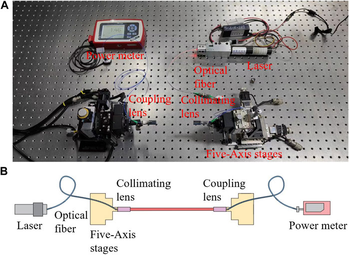
We set up the experimental optical path as shown in Figure 11, using a He-Ne laser tube whose power is stable as the laser light source. The central wavelength of laser is 633 nm. The laser is connected to the collimating lens by an optical fiber to become a collimated space beam and then coupled into the coupling lens. We use an optical power meter to monitor the coupling energy entering the fiber. The lens group is THORLABS’s TC12APC-633 collimating and coupling lens group, with a focal length of 12 mm and a numerical aperture of 0.28.
3.2 Delay range impact
As shown in Figure 12, we test the coupling efficiency under different delay distances and fit the curve according to the experimental data points. The overall trend change of the curve is the same as the theoretical value, and the numerical error is within 2%. Within the interval range of 0–1 m, the maximum coupling efficiency is 95.3%, the minimum coupling efficiency is 92.7%. Compared with theoretical calculations, experiments have factors such as lens group aberration, fiber end face position error, etc., which cause the overall performance of the lens group to decline [24–26]. But the current simulation accuracy is already able to guide the selection of lenses.
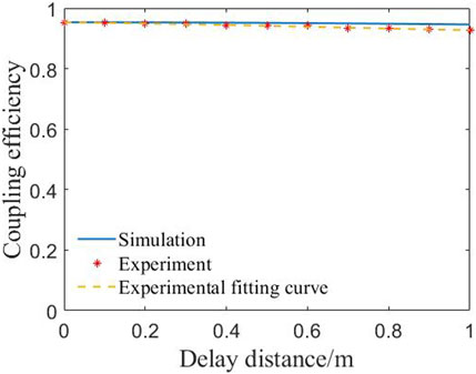
Figure 12. Comparative data graph of experimental measurement and simulation calculation on the relationship between coupling efficiency and delay distance of lens group.
3.3 Coupling lens’s eccentricity and tilt error
Figure 13 and Figure 14 show the coupling efficiency under different coupling lens eccentricity and tilt errors. The overall trend changes are the same as the theoretical values, which can verify the correctness of the simulation calculation. However, due to factors such as lens group aberration, fiber end face position error, etc., the experimental value is slightly lower than the theoretical value. However, the maximum error between theoretical values and experimental measurement results does not exceed 7%.
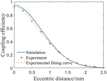
Figure 13. Comparative data graph of experimental measurement and simulation calculation on the effect of coupling lens eccentric distance on coupling efficiency.
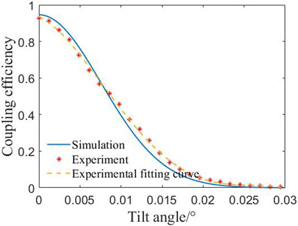
Figure 14. Comparative data graph of experimental measurement and simulation calculation on the effect of coupling lens tilt angle on coupling efficiency.
4 Conclusion
This paper establishes a spatial light transmission model based on scalar diffraction theory for the optical fiber delay line, using coupling efficiency to calculate the insertion loss of the optical fiber delay line equivalently and quantitatively analyzing the effects of structural parameters and assembly errors on coupling efficiency. The research provides theoretical guidance for designing the optical fiber delay line with a large delay range and low insertion loss. An optical fiber delay line experimental device with a delay range of 0–1 m was built. The experimental measurement results and the simulation are roughly the same in change trend, with slight differences in values. The maximum error between theoretical values and experimental measurement results does not exceed 7% and this calculation accuracy is sufficient to guide the selection and installation of lenses. The insertion loss analysis model proposed in this article provides a reference for parameter optimization and design evaluation of high-performance optical fiber delay line. At present, we have successfully applied optical fiber delay lines with a delay range of 0–1 m to the measurement of short coherent Fizeau interferometers. By increasing the measurement chamber length to 50 cm the instrument can be applied to more measurement scenarios. In addition, by optimizing the insertion loss of the optical fiber delay line, we have improved the energy utilization efficiency of the laser. At present, the exposure time of the camera in the short coherent Fizeau interferometer has been reduced from 3 ms to 1 ms, reducing the impact of vibration, turbulence and temperature on measurement accuracy and improving the accuracy of the instrument.
Data availability statement
The original contributions presented in the study are included in the article/Supplementary material, further inquiries can be directed to the corresponding author.
Author contributions
KW: Investigation, Methodology, Writing–original draft. AL: Conceptualization, Writing–review and editing. XK: Investigation, Writing–review and editing. ZW: Conceptualization, Writing–review and editing. RZ: Writing–review and editing. WZ: Supervision, Writing–review and editing.
Funding
The author(s) declare financial support was received for the research, authorship, and/or publication of this article. This work was supported by the National Science and Technology Major Project of the Ministry of Science and Technology of China (Grant No. 2021YFF0701300).
Conflict of interest
The authors declare that the research was conducted in the absence of any commercial or financial relationships that could be construed as a potential conflict of interest.
Publisher’s note
All claims expressed in this article are solely those of the authors and do not necessarily represent those of their affiliated organizations, or those of the publisher, the editors and the reviewers. Any product that may be evaluated in this article, or claim that may be made by its manufacturer, is not guaranteed or endorsed by the publisher.
References
1. Riza NA, Arain MA, Khan SA. Hybrid analog-digital variable fiber-optic delay line. Lightwave Tech J (2004) 22(2):619–24. doi:10.1109/JLT.2004.824383
2. Zhao XC, Tao SX, Liu NW, Wen WF, Peng QX. Design and experimental verification of precision optical fiber delay line. Opt Precision Eng (2014) 22(10):2622–6. doi:10.3788/OPE.20142210.2622
3. Han Q, Lv KC, Li JF, Li YG, Chen SP. Research on a novel fiber Bragg grating thermal tuning scheme. Acta Physica Sinca (2004) 53(12):4. doi:10.1088/1009-0630/6/5/011
4. Italia V, Pisco M, Campopiano S, Cusano A, Cutolo A. Chirped fiber Bragg gratings for electrically tunable time delay lines. IEEE J Selected Top Quan Elect (2005) 11(2):408–16. doi:10.1109/jstqe.2005.846533
5. Maleki L, Matsko AB, Savchenkov AA, Ilchenko VS. Tunable delay line with interacting whispering-gallery-mode resonators. Opt Lett (2004) 29(2):626. doi:10.1364/ol.29.000626
6. Raz O, Rotman R, Danziger Y, Tur M. Implementation of photonic true time delay using high-order-mode dispersion compensating fibers. Photon Tech Lett IEEE (2004) 16(5):1367–9. doi:10.1109/LPT.2004.826263
7. Fan XH. Research on the key technologies of low-coherence Fizeau dynamic interferometer. dissertation. Beijing: University of Chinese Academy of Sciences (2019).
8. Cheng J, Feng JX, Li YJ, Zhang KS. Measurement of low-frequency signal based on quantum-enhanced fiber Mach-Zehnder interferometer. Acta Physica Sinca (2018) 67(24):6. doi:10.7498/aps.67.20181335
9. Liang YM, Zhou DC, Meng FY, Wang MW. A new broadband fiber light source for optical coherence tomography. Acta Physica Sinca (2007) 56(06):3246–50. doi:10.7498/aps.56.3246
10. Liang LCinventor. A fiber optic delayer with high adjustment stability (2018). Chinese patent CN107544114A.
11. Huo JF. Development of the optical delay line for larger range. master’s thesis. Zhejiang: China Jiliang University (2018).
13. Chi ZY. Fiber optics, theories and applications. 2nd ed. Beijing: China Publishing House of Electronics Industry (2014). p. 88.
14. Thorlabs. Triplet fiber optic collimators/couplers (2024). https://www.thorlabschina.cn/newgrouppage9.cfm?objectgroup_id=5124 (Accessed February 2, 2024).
15. Duan L, Xu RQ, Song YB, Tan SD, Liang CB, Xu FJ, et al. Theoretical model and numerical study of effect of target reflected light on high-power fiber laser. Acta Physica Sinca (2023) 72(10):104203–19. doi:10.7498/aps.72.20222464
18. Nascov V, Logofătu PC. Fast computation algorithm for the Rayleigh-Sommerfeld diffraction formula using a type of scaled convolution. Appl Opt (2009) 48(22):4310–9. doi:10.1364/AO.48.004310
19. Voelz DG, Roggemann MC. Digital simulation of scalar optical diffraction: revisiting chirp function sampling criteria and consequences. Appl Opt (2009) 48(32):6132–42. doi:10.1364/AO.48.006132
20. Shen F, Wang A. Fast-Fourier-transform based numerical integration method for the Rayleigh-Sommerfeld diffraction formula. Appl Opt (2006) 45(6):1102–10. doi:10.1364/ao.45.001102
21. Matsushima K, Schimmel H, Wyrowski F. Fast calculation method for optical diffraction on tilted planes by use of the angular spectrum of plane waves. J Opt Soc America A Opt Image Sci Vis (2003) 20(9):1755–62. doi:10.1364/JOSAA.20.001755
22. Wagner RE, Tomlinson WJ. Coupling efficiency of optics in single-mode fiber components. Appl Opt (1982) 21(15):2671–88. doi:10.1364/ao.21.002671
23. Yang XG, Huang YM. Misalignment error anglysis in laser interference length measurement. Acta Ph HOT ONICA SINICA (2010) 39(02):311–5. doi:10.3788/gzxb20103902.0311
24. Bian Y, Li Y, Li W, Hong X, Qiu J, Chen E, et al. The impact of optical system aberration and fiber positioning error on the FMF coupling efficiency of an FSO receiver under atmospheric turbulence. J Opt (2022) 24(8):085701. doi:10.1088/2040-8986/ac733b
25. Zhou YY, Yu FX, Liu SM, Xu L. Discusion between the quality of optical fiber end face and optical property. Opt Tech (2005) 31(6):3. doi:10.3321/j.issn:1002-1582.2005.06.020
Keywords: fiber delay line, scalar diffraction, fiber coupling, insertion loss, lens group
Citation: Wang K, Liu A, Kong X, Wu Z, Zhang R and Zhang W (2024) Design of optical fiber delay line with large delay range and low insertion loss. Front. Phys. 12:1362101. doi: 10.3389/fphy.2024.1362101
Received: 27 December 2023; Accepted: 13 February 2024;
Published: 26 February 2024.
Edited by:
Tao Li, Nanjing University of Science and Technology, ChinaReviewed by:
Preeti Gupta, Leibniz Institute for Solid State and Materials Research Dresden (IFW Dresden), GermanyMin Wang, Beijing Academy of Quantum information Sciences, China
Copyright © 2024 Wang, Liu, Kong, Wu, Zhang and Zhang. This is an open-access article distributed under the terms of the Creative Commons Attribution License (CC BY). The use, distribution or reproduction in other forums is permitted, provided the original author(s) and the copyright owner(s) are credited and that the original publication in this journal is cited, in accordance with accepted academic practice. No use, distribution or reproduction is permitted which does not comply with these terms.
*Correspondence: Wenxi Zhang, emhhbmd3eEBhaXJjYXMuYWMuY24=
 Kai Wang
 Anqi Liu1