 W. W. Heidbrink1*
 L. R. Baylor2
 M. Büscher3,4
 R. W. Engels3A. V. Garcia5A. G. Ghiozzi5G. W. Miller6A. M. Sandorfi7
 X. Wei8X. Zheng7
- 1Physics and Astronomy, University of California, Irvine, Irvine, CA, United States
- 2Oak Ridge National Laboratory, Oak Ridge, TN, United States
- 3Forschungszentrum Jülich, Jülich, Germany
- 4Department of Physics, Heinrich-Heine University Düsseldorf, Düsseldorf, Germany
- 5Oak Ridge Associated Universities, Oak Ridge, TN, United States
- 6Radiology and Medical Imaging and Biomedical Engineering, University of Virginia, Charlottesville, VA, United States
- 7Department of Physics, University of Virginia, Charlottesville, VA, United States
- 8Jefferson Laboratory, Newport News, VA, United States
The use of spin polarized fuel could increase the deuterium-tritium (D-T) fusion cross section by a factor of 1.5 and, owing to alpha heating, increase the fusion power by an even larger factor. Issues associated with the use of polarized fuel in a reactor are identified. Theoretically, nuclei remain polarized in a hot fusion plasma. The similarity between the Lorentz force law and the Bloch equations suggests polarization can be preserved despite the rich electromagnetic spectrum present in a magnetic fusion device. The most important depolarization mechanisms can be tested in existing devices. The use of polarized deuterium and 3He in an experiment avoids the complexities of handling tritium, while encompassing the same nuclear reaction spin-physics, making it a useful proxy to study issues associated with full D-T implementation. 3He fuel with 65% polarization can be prepared by permeating optically-pumped 3He into a shell pellet. Dynamically polarized 7Li-D pellets can achieve 70% vector polarization for the deuterium. Cryogenically-frozen pellets can be injected into fusion facilities by special injectors that minimize depolarizing field gradients. Alternatively, polarized nuclei could be injected as a neutral beam. Once injected, the lifetime of the polarized fuel is monitored through measurements of escaping charged fusion products. Multiple experimental scenarios to measure the polarization lifetime in the DIII-D tokamak and other magnetic-confinement facilities are discussed, followed by outstanding issues that warrant further study.
1 Introduction
If the nuclear spins of deuterium and tritium are both aligned parallel to the magnetic field, the deuterium-tritium (D-T) fusion cross section is 50% larger than for randomly oriented nuclei. Over 4 decades ago [1], Kulsrud et al. predicted that the spins remain aligned sufficiently long in the reactor environment to increase the fusion power but no experimental tests of this prediction were ever performed. Now, however, polarized sources are available that enable experimental tests. This paper summarizes both specific plans to measure the lifetime of spin polarized fuel in the DIII-D tokamak and outlines desirable avenues for additional research.
Numerous technological and physical challenges must be overcome for a successful polarization lifetime experiment. Figure 1 illustrates many of these for one of the planned experiments. Polarized D fuel in the form of a solid LiD pellet is prepared in a multi-step process. In parallel, polarized 3He is diffused into a glow-discharge-polymer shell pellet. Both pellets are injected into the tokamak by specially-designed injectors that preserve the nuclear polarization. Once inside the device, the pellets ablate, ionizing the D and 3He nuclei. Some nuclei that are transported to the hot center of the plasma undergo a D-3He fusion reaction. Prior to a reaction, electromagnetic fields may depolarize the nuclei. The fusion reactions produce high-energy, unconfined reaction products that collide with the vacuum vessel wall; the polarization of the reactants is inferred from the angular distribution of fusion reaction products. A specially designed plasma scenario that provides adequate fusion reaction rates without competing backgrounds is required.
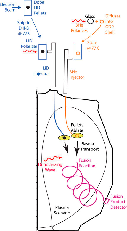
Figure 1. Schematic illustration of major steps in the DIII-D D-3He lifetime experiment.
The planned DIII-D experiments are based upon two recent publications. The first publication [2] describes the nuclear physics and preparation of polarized LiD and 3He pellets for injection into the tokamak. The second publication [3] focuses on experimental scenarios and charged-fusion product detection. The present manuscript incorporates brief summaries of these two publications. The paper begins with a survey of issues of importance in a reactor (Section 2). Next, depolarization mechanisms are discussed, including a heuristic explanation for the theoretical prediction of long polarization lifetimes (Section 3). Section 4 describes planned and prospective polarized sources. Section 5 is devoted to the operational requirements for experimental polarization lifetime measurements and lists numerous possible experiments. The paper concludes with a summary and suggestions for future work.
2 Reactor considerations
The most obvious benefit of spin polarized fuel is that it eases the requirements for energy gain in a reactor. The effect is particularly important for concepts with relatively low values of fusion Q. (Here Q is the ratio of fusion power produced to power delivered to the plasma.) Since virtually all reactor concepts rely on charged fusion products to further heat the fuel, the gain in Q associated with spin polarization is greater than the 50% increase in fusion cross section. For example, in a realistic treatment of an ITER Q = 12 D-T plasma, Q is
But, even for configurations that are expected to ignite, a 50% enhancement in the cross section has very positive consequences. As an example, consider a compact fusion power plant design with parameters as presented in [4]. Figure 2 shows the impact of the increased fusion cross section due to the use of spin-polarized fuel on the net electric power generation of the plant, as calculated in the fusion synthesis engine (FUSE) framework [5]. FUSE calculates an equilibrium from input scalar quantities, while the effect of transport on kinetic profiles is assumed to scale according to the ITER H98y2 confinement scaling [6]. A factor of 1.5 enhancement to the fusion cross section modifies the resulting fusion power for cases with optimally polarized fuel. The final net electric power output is determined by a fully self-consistent balance-of-plant model. The simulations predict an overall increase in net electric power of
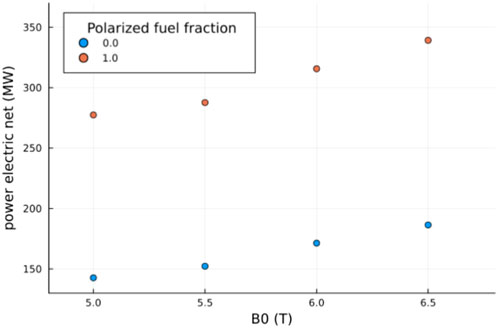
Figure 2. Comparison of the net electric power produced in a fusion power plant with and without spin polarized D-T fuel as a function of reactor magnetic field at the magnetic axis. (In order to keep the safety factor q constant, the plasma current is also scaled with B0).
Another important benefit of spin polarized fuel is a reduction in required tritium inventory. In the generic fuel cycle for a D-T fusion plant [7], deuterium and tritium are injected into the plasma (most likely in the form of solid pellets). Unfortunately, only a small fraction of the injected fuel undergoes a fusion reaction before it escapes the plasma. (The characteristic time for a particle to escape is known as the “particle confinement time” τp.) Once a fuel ion has escaped the confinement region in the plasma core (with its closed field lines), it travels along open field lines to a divertor region where escaping fuel is exhausted from the device. External to the main chamber, tritium and deuterium are separated and formed into solid pellets for reinjection into the main chamber.
Tritium does not occur naturally; moreover, its 12.33-year half life means that storing excess tritium is wasteful. A 50% increase in the probability of a reaction in each injection cycle ultimately reduces the required tritium inventory. Since tritium is hazardous, rare, and expensive, this is a clear benefit of spin polarized fuel.
Another issue associated with the tritium inventory is harder to assess but could ultimately be problematic. Since tritium does not occur naturally, a reactor must breed tritium. D-T reactor designs include tritium breeding modules that surround the hot plasma core; reactions between 14 MeV neutrons and lithium must produce sufficient tritium to sustain the plant. To achieve a breeding ratio in excess of unity, with some margin for radioactive decay and other inefficiencies, tritium breeding modules must cover a large fraction of the area surrounding the reactor, imposing a severe constraint upon D-T plant design.
The D-T fusion cross section is isotropic for unpolarized fuel but becomes anisotropic for polarized fuel. The differential fusion cross section is [2].
where the polar pitch angle θ is the angle between the emitted charged fusion product (CFP) and the local magnetic field at birth and σ0 depends upon the relative velocity of the reactants. The polarization factors
When the deuterium and tritium spins are aligned parallel to the magnetic field B, Eq. 1 implies that fusion products are preferentially emitted perpendicular to the magnetic field. The resultant change in the directionality of the neutron emission could improve the tritium breeding ratio of some modules, reducing the requisite area needed by the modules. On the other hand, the enhanced neutron flux might exceed manageable heat or radiation loads. In tokamak geometry, the neutron flux to vertically-located divertors increases, aggravating challenges associated with protecting vulnerable divertor components. Whether neutron directionality is a liability or benefit depends upon the magnetic fusion concept and the actual geometry of a particular implementation.
Articles published shortly after Kulsrud’s seminal work [1, 8] argued that, because the confinement time is short compared to the fusion burnup time and because nuclei rapidly depolarize at a metallic wall, the utility of spin polarized fuel would be very limited [9]. Although it is certainly true that depolarization at most types of metal walls is virtually guaranteed, modern reactor designs assume that very few ions return directly to the plasma after a collision with a wall in the process known as “recycling.” In modern plant designs, nearly all escaping fuel ions are exhausted to the divertor, where they are reprocessed. As discussed below, recycling is an important consideration in planned experiments, but it does not negate the advantages of polarized fuel for a burning plasma [2].
A final issue for reactor design is the cost of spin polarization. Since fuel must be reprocessed anyway, it appears likely that spin polarization adds little to plant complexity. Nor is it likely to add appreciably to the capital cost of the plant. A more relevant concern is the energy efficiency of polarization. The process used to polarize the fuel must consume considerably less energy than the energy released in a fusion reaction times the probability that a fuel ion will react each time it is injected. In other words, the energy of polarization (including any inefficiencies) must be far less than 0.01 × 18 MeV = 100 keV, a requirement that seems easily satisfied.
3 Depolarization mechanisms
Physically, there are three depolarization mechanisms of principal concern [8].
The first is trivial. If the magnetic field is zero in a particular region, the reference axis for the polarization is lost. Since nearly all magnetic configurations have non-zero magnetic field throughout the confinement region, this depolarization mechanism is irrelevant inside the plasma for tokamaks, stellarators, and most other confinement concepts. An exception is the magnetic configuration known as a “field reversed configuration” (FRC), since an ideal FRC has a field null at the center of the confinement region. For all configurations, injected nuclei cannot cross a field null on their way to the plasma. A guide field is required during injection. Estimates indicate that the required guide field for deuterium is O (0.01) T and even less for 3He [2].
The second mechanism is interaction with bound electrons, most commonly through the hyperfine interaction. In fact, hyperfine interactions with bound electrons polarize the fuel in the first place (Section 4). However, in the reactor environment, ions with low atomic numbers Z like deuterium and helium are fully ionized, so there are no bound electrons to interact with the nuclei. Singly ionized helium does have a bound electron that couples to the nuclear spin but estimates indicate that only a few percent of injected polarized 3He lose their polarization during the relatively rapid ionization process [2].
A related concern is collisions of the fuel pellet with the pellet injector guide tube but estimates indicate that the associated losses are minimal [2].
The mechanism of greatest concern is resonance at the precession frequency of the nucleus. This frequency is a multiple g of the ordinary ion cyclotron frequency ωci = ZeB/m. The gyromagnetic ratio g is of order unity. If the nucleus experiences a wave with left-handed circular electric-field polarization at this frequency in its rest frame, rapid depolarization occurs [8]. Applications that use rotating magnetic fields to induce spin flips utilize this method.
The magnetic fusion plasma is filled with a vast spectrum of electromagnetic and electrostatic waves so, naively, one might expect rapid depolarization caused by precession resonances. This is not necessarily the case, however. Detailed calculations [8] indicate that, although the nuclei are constantly bombarded by Coulomb collisions in the plasma environment, Coulomb collisions cause negligible depolarization during a particle confinement time τp. Similarly, the spectrum of MHD and drift waves are also expected to cause negligible depolarization for reasons explained heuristically here [10].
Ion orbits in the magnetic field are governed by the Lorentz force law,
where v is the particle velocity and
High-field magnetic confinement devices like tokamaks and stellarators usually conserve the magnetic moment μ. Indeed, one of the most successful theories of fusion plasmas, gyrokinetic theory [12], is predicated on conservation of μ. In the absence of instabilities or waves with frequencies close to the ion cyclotron frequency, μ is conserved.
When μ is conserved, it is expected that the nuclear polarization will also be conserved. Here’s why. The bulk polarization of the nuclei P is governed by the Bloch Equation [13],
Note that, apart from the factor g, Eqs 2, 3 are identical. Since g is of order unity, this implies that the polarization has a constant of motion
More rigorously, the evolution of the velocity and polarization vectors are governed by a single kinetic equation that concurrently evolves both quantities with terms like those on the right-hand side of Eqs 2, 3, and also includes the fluctuating fields that break μ and μp [14]. The conclusions of this more rigorous analysis are consistent with the heuristic argument presented here.
Of course, waves in the ion cyclotron range of frequencies violate the condition ω ≪ ωci required for μ conservation and could depolarize the nuclei. There are two potential sources of waves with ω ∼ ωci: plasma-generated instabilities and externally launched waves. Many magnetic confinement facilities launch high-power waves in the ion cyclotron range of frequencies (ICRF) to heat the plasma. If the frequency of the RF wave matches the precession frequency somewhere in the plasma, these large-amplitude wave fields will almost certainly depolarize the nuclei. In terms of the ordinary deuterium gyrofrequency ωcD = eB/2mp, the deuterium nuclear precession frequency occurs at 0.86ωcD, the 3He precession frequency is at 4.255ωcD, and the tritium precession frequency is at 5.96ωcD. Fortunately, in many configurations, resonance at the precession frequency occurs outside the plasma. Figure 3 shows an example for a moderate aspect-ratio tokamak that launches waves that resonate with the orbital 3He gyrofrequency at
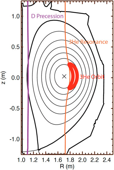
Figure 3. RF waves that resonate with 3He minority ions near the center of the tokamak do not resonate at the deuterium or 3He precession frequencies in a moderate-aspect ratio tokamak. The approximately vertical lines indicate the ωRF = 2eB/3mp resonance with the fundamental 3He cyclotron frequency and with the ωRF = 0.86ωcD deuterium precession resonance. The projection of the orbit of a high-energy 3He ion that is accelerated by the ICRF heating is also shown, as are the magnetic axis (X), flux surfaces (thin lines), and the “separatrix” boundary between closed field lines and open field lines (thick line).
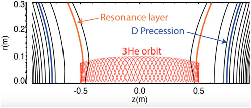
Figure 4. In a magnetic mirror, the orbits of high-energy 3He ions that are accelerated near their turning points do not traverse the deuterium precession resonance. The lines indicate magnetic field contours. The projection of the orbit of a high-energy 3He ion heated by the RF waves is also shown.
Instabilities in the ICRF are of greater concern. Under some operating conditions in tokamaks and stellarators, waves at the cyclotron frequency and its harmonics are driven unstable by super-thermal ions or electrons [16]. Waves with frequencies just below the cyclotron frequency are also observed [17]. If these instabilities are excited, the waves may propagate to locations in the plasma where the wave frequency matches a precessional frequency, causing depolarization. Clearly, polarization lifetime experiments should explore operational regimes with and without instabilities near the ion cyclotron frequency.
4 Polarized fuel
Although 100 keV ion energies are appreciable in plasma physics, in nuclear physics, 100 keV is a low energy. At the “low” energies of fusion experiments, the nuclear physics of the D-T fusion reaction is virtually identical to the nuclear physics of the D-3He fusion reaction [2]. Consequently, to avoid the hazards and complexity of a tritium experiment, our research program uses D-3He reactions as a proxy for D-T.
Polarized pellets are discussed in detail in [2], so only a summary is given here.
4.1 Polarized LiD pellets
Over the past decades, a variety of deuterated molecules have been used to create solid targets of polarized deuterium for nuclear and particle physics experiments [18, 19]. These utilize a dynamic nuclear polarization (DNP) process, in which molecular electrons are first polarized in a several Tesla magnetic field at relatively low temperatures (
Lithium-deuteride is a solid at room temperature and is readily formed into mm-scale pellets suitable for an SPF study. The DNP process requires the introduction of a small fraction (
The use of LiD as the carrier for polarized deuterium requires a custom engineered polarizer, incorporating a DNP microwave circuit with RF coils that generate nuclear magnetic resonance (NMR) signals for polarization monitoring and spin manipulations, coupled to a dedicated cryogenic injection gun. The low operating temperatures of the polarizer require either 3He or 4He dilution cooling to reach ∼0.2 K, or a pumped 3He system operating at ∼0.3 K. In the polarizer, the LiD sample needs to be centered within a 6–8 T superconducting solenoid. While fringe fields from such a magnet might be of concern for plasma operations, the magnet could be shielded. Alternatively, since the bore of the solenoid could be small, this would require a relatively low inductance magnet that could be ramped down quickly (or even intentionally quenched) following the transfer of polarized pellets to the injection gun. The latter could operate at 4 K without noticeable loss in polarization over the short period (tens of seconds) preceding injection.
Pellets with
4.1.1 Fabricate LiD pellets
Cylindrical pellets of LiD will be made by fusing (melting) powdered material in a gold-lined cavity, heated within an inert gas-filled chamber. Raising the temperature at
4.1.2 Dope LiD pellets with paramagnetic centers
LiD has only paired molecular electrons with no net electron spin. In the dynamic nuclear polarization (DNP) process, a few percent of the LiD molecules must be ionized. Those ionized molecules are paramagnetic and their electrons can be polarized when exposed to high fields and low temperatures. These paramagnetic centers are introduced by irradiation with an electron beam while the LiD is held at
4.1.3 Storage of Paramagnetically doped LiD
If irradiated LiD is raised to room temperature, the paramagnetic centers will decay away as the ionized sites become neutralized. However, if kept colder than 190 K, the time scale for this recombination process becomes extremely long, and at 77 K the doped LiD pellets can be stored indefinitely. An LN2 storage cryostat at the magnetic-fusion facility will store the pellets.
4.1.4 LiD polarizer
The LiD polarizer contains a dilution refrigerator (DF) capable of reaching 200 mK, a built-in superconducting solenoidal 6-to-8 T magnet, a pellet handling system to load and dispense LiD pellets, a microwave system to transfer polarization between electrons and deuterons, and an NMR system for polarization monitoring. Post-irradiated LiD pellets are loaded into a polarization chamber located at the center of the high-field magnet and cooled by the DF mixing chamber to provide the required low temperature and strong magnetic field. The electrons in the LiD molecule polarize quickly. The deuterium is polarized by continuously inducing hyperfine transitions between electrons and deuterium nuclei with microwaves at the appropriate frequency. Since the relaxation time of the bound electrons is much shorter than that of the deuteron, the electrons repolarize quickly while the D polarization can be accumulated over time. Nuclear magnetic resonance (NMR) coils located inside the LiD chamber are used to calibrate and monitor the pellet polarization. Ultimately, the polarized LiD pellet is transferred to the pellet gun (Sec. 4.3).
4.2 Polarized 3He pellets
Hybrid spin-exchange optical pumping (SEOP) can be used to polarize 3He [25]. With this technique, a glass bulb (polarizing cell) containing pressurized 3He, together with small amounts of rubidium and potassium (
For medical imaging studies [29], high polarization and high batch volume are the primary concerns. In contrast, for magnetic-fusion fueling, the primary requirements are high 3He polarization at high pressure, rather than high volume. Accordingly, a figure of merit for fusion applications is the polarization density in the polarization cell (3He polarization times pressure at room temperature). Work is underway at the University of Virginia to maximize this figure of merit by exploring empirical tradeoffs among cell size, 3He density, optical pumping temperature, and laser power. Electron paramagnetic resonance (EPR) and adiabatic fast-passage NMR systems for monitoring alkali electron polarization and measuring absolute 3He polarization are employed to quantify the tradeoffs.
An ambitious goal is to generate a 25-bar reservoir of 80% polarized 3He as a source for pellet permeation into
Work is underway to construct permeation vessels that can withstand higher maximum pressure and to incorporate a means of stepping down the 3He reservoir pressure in acceptable increments, to avoid exposing pellets to a pressure gradient exceeding the known buckling pressure. After 2 years of optimization experiments, an optimized polarizer for use at magnetic-fusion facilities will be fabricated.
4.3 Pellet injector
For a spin-polarization lifetime measurement, the polarized pellets must be delivered to the plasma with polarization largely intact. Both deuterium pellets and GDP pellets are routinely injected into fusion facilities like DIII-D but additional issues affect the design of SPF injectors.
One issue is that the pellets cannot cross a region of low magnetic field without losing their polarization. For deuterium, a field of a few hundred Gauss suffices to maintain the polarization; for 3He, 25 G is sufficient [2]. Such fields can be generated by a solenoid winding wrapped around the guide tube, with a tapered wire density that decreases as the tube enters the fringe field of the tokamak. Additionally, the pellets cannot rapidly cross a large field gradient that appears at the nuclear precession frequency in the particle’s frame. While injection velocities are typically 500–1,000 m/s, this and any tumbling motion down the guide tube are significantly slower than the Larmor frequencies of either D or 3He. As a result, the D and 3He spin vectors will simply follow the net local field as the tokamak fringe field rises and the guide tube field falls. Once inside the hydrogen plasma, the spins will align along the local magnetic field.
Another issue is that the polarized nuclei must ultimately fuel the high temperature plasma core. A large pellet can penetrate to the core but can cause excessive cooling. In a tokamak, pellets injected on the high field side bend toward the magnetic axis so injection from smaller major radius is preferred [30].
The third issue is the most challenging. The pellets depolarize at elevated temperatures, so deuterium pellets should be injected at
Experiments will compare the parallel spin configuration that enhances the fusion cross section with both unpolarized fuel and with the anti-parallel configuration that suppresses it. The anti-parallel spin configuration can be prepared within the cryo-gun, using an RF transition (an Adiabatic Fast Passage, or AFP) to flip the sub-state population so that the spin of one species (but not both) is aligned against the local magnetic field [31].
In existing solid (unpolarized) D2 pellet guns, samples are propelled from the 4 K barrel of a cryo-gun to the tokamak by room temperature helium gas. Downstream of the
A suitable pellet injector that could inject polarized cylindrical LiD pellets at high speeds (
Figure 5. Concept for the LiD pellet loader into a LHe cooled gas gun.
Inside the plasma, the physics of pellet injection is well established [35, 36]. As it traverses the plasma, the solid material erodes (or “ablates”) at a rate that is determined by the balance between the energy flux provided by the plasma and the flux required to remove the particles from the pellet surface and disassociate, ionize, and accelerate them. A shielding cloud of neutral gas retards the flux of plasma energy to the pellet surface, increasing penetration into the plasma. Magnetic shielding caused by the partial expulsion of the magnetic field from the cloud interior by the expanding plasma may also occur [37]. Large electric fields form [38]. Particularly during the phase when 3He is singly ionized, these rapidly-varying fields may induce hyperfine transitions [2]. To our knowledge, detailed theoretical treatment of effects that might cause nuclear depolarization during the ablation process is a topic for future work.
4.4 Polarized neutral beam
As discussed in Section 5, establishing suitable operational conditions for experiments with polarized pellets can be challenging, especially in smaller magnetic fusion devices. If a sufficiently intense neutral beam was available, many of these operational challenges would be ameliorated.
Polarized neutral beams are widely used in nuclear physics experiments [39] but their currents are far too low for use in a fusion polarization-lifetime experiment, where the fuel must be injected in times short compared to the particle confinement time. “Optical pumping” between quantum states is the established method to induce nuclear polarization [39]. For this, very powerful lasers are used to induce transitions between different electronic states; the energy of the involved photons is of the order of several eV.
Fusion devices are routinely heated by intense 25-120 keV neutral-beam sources with megawatts of power. Ordinarily, the majority of injected atoms are in the ground state. Although efficient methods to polarize metastable atoms using a Sona coil [40] were recently demonstrated [41], techniques to polarize ground-state neutral beams do not presently exist. The ideal neutral beam for spin-polarized fusion experiments would inject > 1018 deuterium atoms per second with > 50% polarization.
5 Experimental scenarios
5.1 General considerations
A general principle of experimental physics is that relative measurements are easier and more accurate than absolute measurements. That is certainly the case for detection of the degree of spin polarization in the plasma. For D-3He reactions, the emissivity (reaction rate per unit volume) is nDnHe⟨σv⟩, where nD and nHe are the deuterium and 3He densities, and ⟨σv⟩ is the cross section σ and relative velocity v averaged over the deuterium and 3He distribution functions. Absolute determination of the effect of polarization on the reaction rate requires (i) absolutely calibrated fusion product detectors and (ii) accurate measurements of the D and 3He distribution functions and density profiles; sufficiently accurate data for the latter are unavailable at typical facilities [3]. On the other hand, since the emission angle of fusion reaction products is sensitive to the polarization state of the reacting nuclei through the differential cross section (Eq. 1), accurate relative measurements of the angular dependence of escaping fusion products are readily obtainable and provide sufficient accuracy to determine the polarization lifetime [3]. Figure 6 illustrates the basic idea behind accurate relative polarization measurements.
Figure 6. Angular dependence of the differential cross section dσ/dΩ for maximally-aligned parallel D and 3He nuclear spins (blue line), anti-parallel spins (red line), and randomly oriented spins (thick green line). The angular dependence for unpolarized 3He and tensor-polarized deuterium
Charged fusion reaction products are usually born in the hot core of the plasma but they are detected near the vacuum vessel wall. The angle θ in Eq. 1 is the angle between the emitted velocity vector and the magnetic field in the center-of-mass frame at the birth location. In a magnetic confinement device, the angle between v and B changes as the fusion product travels to the wall. The difference depends upon the orbit size, which scales as
Figure 7. Projected orbits of 3.6 MeV alphas with larger (dark blue), intermediate (light blue), and smaller (red) values of |v‖/v| at birth in DIII-D. For these alphas, v ⋅B at birth determines where the ions strike the wall, so the relative signals from a poloidal array of alpha detectors is an effective way to diagnose polarization.
Since the orbits of 3.6 MeV alphas are only
In smaller devices with poorer confinement than DIII-D, the angle of emission is largely retained for all escaping fusion products, so diagnosis is similar to 14.7 MeV proton detection in DIII-D.
Because the escaping fusion products are poorly confined, the accuracy of inference of the polarization state is insensitive to errors in the magnetic field reconstruction [3]. Uncertainty in the emission profile is a larger source of error [3].
The strong angular dependence of the emitted fusion products illustrated in Figure 6 is for the case where both deuterium and 3He are polarized. Eq. 1 indicates that, if only one species is polarized, the angular dependence is weaker (dashed line in Figure 6); moreover, tensor-polarization of the deuterium is required.
The challenge with using D-3He as a proxy for the D-T reaction is that, owing to the larger Coulomb repulsion of helium with deuterium, the fusion cross section is very low at O (10 keV) energies. To obtain adequate counting statistics in charged fusion product detectors, for D-3He, relative energies of the reactants of O (100 keV) are required. In existing devices, relative energies this large require one of the following.
1. Neutral beam injection of O (100 keV) beams for one of the reacting species.
2. ICRF acceleration that creates a fast-ion deuterium or 3He population with O (100 keV) energies. For example, 3He-minority heating can produce large D-3He reaction rates in a modest-size device [42].
3. A thermonuclear plasma with ion temperature Ti ≳ 10 keV. [Because the majority of reactions in a thermonuclear plasma occur between oppositely directed ions in the tails of the thermal distributions, the relative energy of most reactants in a Ti = 10 keV plasma is of O (100 keV).]
Because the Coulomb repulsion is weaker for deuterium-deuterium fusion reactions, practical reaction rates are accessible at significantly lower energies than for D-3He. For example, at Ti = 5 keV, the reactivity ⟨σv⟩ for D-D reactions is comparable to the reactivity of D-3He reactions at Ti = 10 keV. An additional advantage of deuterium is that it is employed routinely at most magnetic fusion facilities. Unfortunately, for the case where both reactants are polarized, the D-D differential cross section at relevant plasma energies is unknown and controversial. In one compilation [43], different theoretical models predict enhancement factors
On the other hand, for the case where one deuterium reactant is polarized but the other is unpolarized, the differential cross section is known accurately at relevant energies [45, 46]. Even for unpolarized D nuclei, the unpolarized D-D differential cross section (dσ/dΩ)0 depends upon the angle of fusion product emission [47]. Becker et al. [45] provide formulas for the additional angular dependence when one of the reactants is polarized. The altered differential cross section (dσ/dΩ)/(dσ/dΩ)0 depends upon the angle between the incident beam and the magnetic field B, the gyroangle of the incident beam, the angle of emission of the 3-MeV proton relative to B, and the degree of vector and tensor polarization
Figure 8. Angular dependence of the differential D-D cross section relative to the unpolarized dependence ⟨dσ/dΩ⟩/(dσ/dΩ)0 for maximally-aligned D nuclear spin
In general, the ideal experimental facility has the following:
1. Large count rate (
2. Escaping fusion products that are sensitive to dσ/dΩ for the selected polarization of the reactants,
3. Reactor-relevant depolarization mechanisms,
4. Long particle confinement time for the polarized nuclei (in order to measure potentially long polarization lifetimes), and
5. Modest volume (so modest-size polarized sources produce appreciable densities).
5.2 Specific scenarios
5.2.1 Thermonuclear D-3He scenario in DIII-D
The primary target for the funded DIII-D experiments is a thermonuclear plasma with polarized LiD and 3He pellet injection. Owing to the strong sensitivity of dσ/dΩ (Figure 6), even for modest pellet polarizations of
The scenario analyzed in [3] underestimated the severity of pellet cooling. Pellets cool the plasma for two reasons. First, injected neutral ions become fully stripped in the plasma core; LiD pellets include lithium as well as deuterium and 3He shell pellets include hydrogen and carbon as well as 3He. It takes 13.6 eV, 79 eV, 203 eV, and 978 eV to strip hydrogen, helium, lithium, and carbon, respectively. Second, the injected electrons and ions are cold, so they subtract energy from the existing electron and ion populations when they equilibrate. In a zero-dimensional analysis that assumes (i) quasineutrality and (ii) no additional energy losses, the local energy density before pellet injection ub is related to the energy density after injection ua and the ionization energy
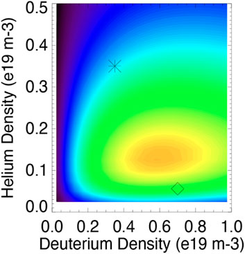
Figure 9. D-3He emissivity nDnHe⟨σv⟩ predicted by zero-dimensional analysis of pellet cooling as a function of nD and nHe. The diamond and asterisk show the values assumed in [2, 3], respectively. Plausible values of Te = 3.9 keV, Ti = 11.5 keV, Te/Ti = 0.5 are assumed. A linear rainbow color map with maximum emissivity of 1.7 × 10¹¹ s−1-m−3 is employed.
DIII-D experiments to develop a high-Ti scenario with co-injected hydrogen beams and pellet injection are planned.
5.2.2 Polarized LiD pellet with unpolarized 3He beam injection scenario in DIII-D
This scenario is described in detail in [3]. To achieve relative energies of O (100 keV), one of the DIII-D neutral beam injectors injects
5.2.3 Polarized LiD pellet with unpolarized D beam injection scenario in DIII-D
In this scenario, an
5.2.4 Polarized LiD pellet in a thermonuclear scenario in DIII-D
In contrast to the previous scenario, in this scenario, both reactants are polarized. To obtain adequate 3-MeV proton count rates, high-power electron cyclotron heating is used to trigger an H-mode, resulting in higher ion temperature and hence higher D-D reaction rates. To minimize unpolarized reactions, the plasma prior to LiD pellet injection is composed of 4He. If a polarization dependence is observed, measurement of its persistence yields a lifetime measurement.
5.2.5 Scenarios with polarized neutral beams
If an intense polarized source is successfully developed, many more scenarios become feasible both at DIII-D and at other facilities. With a polarized deuterium beam and injection of polarized 3He shell pellets, adequate D-3He count rates are obtainable in numerous smaller devices. The only important restriction is that the thermal 3He particle confinement time limits the maximum polarization lifetime that can be measured.
If the D-D differential cross section when both species are polarized does depend upon polarization, similar studies with LiD pellets are feasible and easily implemented.
5.2.6 ICRF scenarios
Polarization lifetime measurements in tokamaks with ion cyclotron heating are also highly desirable. Perhaps the simplest scenario is to use a bulk 4He plasma, inject a polarized 3He pellet, apply ICRF power at the 3He fundamental frequency to create a 3He tail then, once the 3He minority tail is established, a 6LiD pellet is injected to produce a large D-3He reaction rate.
The pros and cons of the four planned DIII-D scenarios are summarized in Table 1.
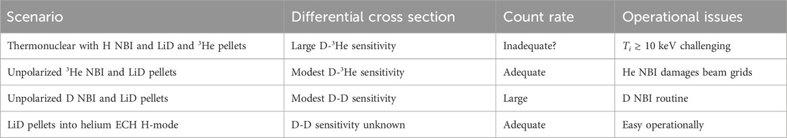
Table 1. Pros and cons of the different DIII-D scenarios to measure the polarization lifetime (NBI = “neutral beam injection”).
6 Conclusion
An experimental program to measure the lifetime of spin polarized nuclear fuel is underway. The potential 50% enhancement in fusion cross section relaxes the plasma physics requirements for a practical magnetic fusion reactor. The theoretical expectation that depolarization lifetimes will be long can be tested in current experiments. Polarized LiD and 3He pellet sources are being designed and fabricated. Relative measurements of escaping fusion products enable inference of the polarization lifetime in several different D-3He and D-D scenarios.
Although the primary focus of future work is to execute the outlined DIII-D research program, two highly desirable extensions are readily identified. First, development of an intense polarized neutral beam source would provide high-energy polarized nuclei with less contaminants than polarized pellets, greatly simplifying experiments at DIII-D and enabling experimental tests at smaller facilities. Second, reliable predictions of the D-D differential cross section at fusion-relevant energies when both nuclei are polarized would enable experiments with lower-energy reactants at both DIII-D and elsewhere.
Once suitable sources are available, a diverse research program to quantify depolarization rates is envisioned, particularly studies of plasmas with and without instabilities and with heating in the ion cyclotron range of frequency. If experiments show that the polarization is preserved, future work should also include quantitative assessment of the reactor issues identified in Sec. 2.
Data availability statement
The raw data supporting the conclusion of this article will be made available by the authors, without undue reservation.
Author contributions
WH: Writing–original draft. LB: Writing–review and editing, Conceptualization. MB: Writing–review and editing. RE: Writing–review and editing. AVG: Writing–review and editing. AGG: Writing–review and editing. GM: Writing–review and editing. AS: Writing–review and editing. XW: Writing–review and editing. XZ: Writing–review and editing.
Funding
The author(s) declare that financial support was received for the research, authorship, and/or publication of this article. This work was partially supported by DOE grant numbers DE-SC0020337 and DE-SC0024689.
Acknowledgments
Valuable discussions with Jay Anderson, Michl Binderbauer, Liu Chen, Cary Forest, Brian Grierson, Mikhail Gryaznevich, Kunal Sanwalka, and Xiaochao Zheng are gratefully acknowledged.
Conflict of interest
The authors declare that the research was conducted in the absence of any commercial or financial relationships that could be construed as a potential conflict of interest.
Publisher’s note
All claims expressed in this article are solely those of the authors and do not necessarily represent those of their affiliated organizations, or those of the publisher, the editors and the reviewers. Any product that may be evaluated in this article, or claim that may be made by its manufacturer, is not guaranteed or endorsed by the publisher.
References
1. Kulsrud R, Furth H, Valeo E, Goldhaber M. Fusion reactor plasmas with polarized nuclei. Phys Rev Lett (1982) 49:1248. doi:10.1063/1.2945625
2. Baylor L, Deur A, Eidietis N, Heidbrink WW, Jackson GL, Liu J, et al. Polarized fusion and potential in situ tests of fuel polarization survival in a tokamak plasma. Nucl Fusion (2023) 63:076009. doi:10.1088/1741-4326/acc3ae
3. Garcia A, Heidbrink W, Sandorfi AM. Conceptual design of DIII-D experiments to diagnose the lifetime of spin polarized fuel. Nucl Fusion (2023) 63:026030. doi:10.1088/1741-4326/acaf0d
4. Weisberg D, Grierson B, Meneghini O-M, Solomon W, Beharrell P, Leuer J, et al. Integrated design and optimization of the advanced tokamak fusion pilot plant. Bull Am Phys Soc (2023).
5. Meneghini O, Slendebroek T, Lyons B, Cote T, Ghiozzi A, Guterl J, et al. Fusion synthesis engine: a next-generation framework for integrated design of fusion pilot plants (fpps). Bull Am Phys Soc (2023).
6. Modelling C, Database IPEGC, Editors IPB. Chapter 2: plasma confinement and transport. Nucl Fusion (1999) 39:2175–249. doi:10.1088/0029-5515/39/12/302
7. Abdou M, Vold E, Gung C, Youssef M, Shin K Deuterium-tritium fuel self-sufficiency in fusion reactors. Fusion Tech (1986) 9:250. doi:10.13182/fst86-1
8. Kulsrud R, Valeo E, Cowley S Physics of spin-polarized plasmas. Nucl fusion (1986) 26:1443–62. doi:10.1088/0029-5515/26/11/001
9. Greenside H, Budny R, Post DE Depolarization of d–t plasmas by recycling in material walls. J Vacuum Sci Tech A: Vacuum, Surf Films (1984) 2:619–29. doi:10.1116/1.572456
12. Brizard AJ, Hahm TS Foundations of nonlinear gyrokinetic theory. Rev Mod Phys (2007) 79:421–68. doi:10.1103/revmodphys.79.421
14. Cowley S, Kulsrud R, Valeo E A kinetic equation for spin-polarized plasmas. Phys Fluids (1986) 29:430–41. doi:10.1063/1.865726
15. Endrizzi D, Anderson J, Brown M, Egedal J, Geiger B, Harvey R, et al. Physics basis for the Wisconsin HTS axisymmetric mirror (WHAM). J Plasma Phys (2023) 89:975890501. doi:10.1017/s0022377823000806
16. McClements K, D’Inca R, Dendy R, Carbajal L, Chapman SC, Cook JWS, et al. Fast particle-driven ion cyclotron emission (ICE) in tokamak plasmas and the case for an ICE diagnostic in ITER. Nucl Fusion (2015) 55:043013. doi:10.1088/0029-5515/55/4/043013
17. Lestz JB, Belova E, Gorelenkov N Hybrid simulations of sub-cyclotron compressional and global alfvén eigenmode stability in spherical tokamaks. Nucl Fusion (2021) 61:086016. doi:10.1088/1741-4326/abf028
18. Crabb D, Meyer W Solid polarized targets for nuclear and particle physics experiments. Annu Rev Nucl Part Sci (1997) 47:67–109. doi:10.1146/annurev.nucl.47.1.67
19. Goertz S, Meyer W, Reicherz G Polarized H, D and 3He targets for particle physics experiments. Prog Part Nucl Phys (2002) 49:403–89. doi:10.1016/s0146-6410(02)00159-x
20. Abragam A, Bouffard V, Roinel Y, Roubeau P A new polarized target material: 6LiD. J de Physique Lettres (1980) 41:309–10. doi:10.1051/jphyslet:019800041013030900
21. Doshita N, Ball J, Baum G, Gautheron F, Goertz S, Hasegawa T, et al. The COMPASS polarized target in 2006 and 2007. In: AIP conference proceedings, Vol. 980 American Institute of Physics (2008). p. 307–11. doi:10.1063/1.2888101
22. Mansfield D, Hill K, Strachan J, Bell M, Scott S, Budny R, et al. Enhancement of tokamak fusion test reactor performance by lithium conditioning. Phys Plasmas (1996) 3:1892–7. doi:10.1063/1.871984
23. Xisheng W, Jiaquan Z The technology of developing a low density lithium hydride or lithium deuteride solid micro-target. China Nucl Sci Tech Rep (2001) 10.
24. Roinel Y Possibility of building a polarized target of 6LiD. Tech Rep CEA Centre D’etudes Nucleaires de Saclay (1981) 458–9. doi:10.1007/978-3-0348-6301-8_51
25. Babcock E, Nelson I, Kadlecek S, Driehuys B, Anderson L, Hersman FW, et al. Hybrid spin-exchange optical pumping of He3. Phys Rev Lett (2003) 91:123003. doi:10.1103/physrevlett.91.123003
26. Mooney KE, Miller GW, Dolph P, Tobias WA, Nelyubin V, Singh J, et al. A 3-liter capacity, hybrid spin-exchange 3He polarizer for medical imaging. In: Proceedings of the 17th annual meeting of ISMRM (2009). p. 2166.
27. Chen W, Gentile T, Ye Q, Walker T, Babcock E On the limits of spin-exchange optical pumping of 3He. J Appl Phys (2014) 116:014903. doi:10.1063/1.4886583
28. Nikroo A, Czechowicz D, Castillo E, Pontelandolfo J Recent progress in fabrication of high-strength glow discharge polymer shells by optimization of coating parameters. Fusion Sci Technol (2002) 41:214–9. doi:10.13182/fst41-214
29. Tafti S, Garrison WJ, Mugler JP, Shim YM, Altes TA, Mata JF, et al. Emphysema index based on hyperpolarized 3He or 129Xe diffusion MRI: performance and comparison with quantitative CT and pulmonary function tests. Radiology (2020) 297:201–10. doi:10.1148/radiol.2020192804
30. Baylor L, Jernigan T, Combs S, Houlberg W, Murakami M, Gohil P, et al. Improved core fueling with high field side pellet injection in the DIII-D tokamak. Phys Plasmas (2000) 7:1878–85. doi:10.1063/1.874011
31. Wei X, Bassa C, D’Angelob A, Deura A, Dezerna G, Kageyaa T, et al. Boosting deuteron polarization in HD targets: experience of moving spins between H and D with RF methods during the E06-101 experiment at Jefferson Lab. In: Proc. XVth int. Workshop polarized sources, targets and polarimetry (2014). p. 9–13.
32. Combs SK, Baylor LR Pellet-injector technology—brief history and key developments in the last 25 years. Fusion Sci Tech (2018) 73:493–518. doi:10.1080/15361055.2017.1421367
33. Combs S, Foust C, Gouge M, Milora S Acceleration of small, light projectiles (including hydrogen isotopes) to high speeds using a two-stage light gas gun. J Vacuum Sci Tech A: Vacuum, Surf Films (1990) 8:1814–9. doi:10.1116/1.576808
34. Milora S, Combs S, Foust C Fast-opening magnetic valve for high-pressure gas injection and applications to hydrogen pellet fueling systems. Rev scientific Instr (1986) 57:2356–8. doi:10.1063/1.1138677
35. Milora S, Houlberg W, Lengyel L, Mertens V Pellet fuelling. Nucl Fusion (1995) 35:657–754. doi:10.1088/0029-5515/35/6/i04
36. Baylor L, Geraud A, Houlberg W, Frigione D, Gadeberg M, Jernigan T, et al. An international pellet ablation database. Nucl fusion (1997) 37:445–50. doi:10.1088/0029-5515/37/4/i02
37. Lengyel L Pellet-plasma interaction: local disturbances caused by pellet ablation in tokamaks. Nucl fusion (1989) 29:37–48. doi:10.1088/0029-5515/29/1/004
38. Parks P, Baylor LR Effect of parallel flows and toroidicity on cross-field transport of pellet ablation matter in tokamak plasmas. Phys Rev Lett (2005) 94:125002. doi:10.1103/physrevlett.94.125002
39. Clegg TB Sources of spin-polarized beams (invited). Rev scientific Instr (1990) 61:385–8. doi:10.1063/1.1141300
40. Sona P. A new method proposed to increase polarization in polarized ion sources of h- and d-. Energia Nucleare (1967) 14:295.
41. Engels R, Büscher M, Buske P, Gan Y, Grigoryev K, Hanhart C, et al. Direct observation of transitions between quantum states with energy differences below 10 nev employing a sona unit. The Eur Phys J D (2021) 75:257. doi:10.1140/epjd/s10053-021-00268-4
42. Chrien R, Strachan J d-3 he reaction measurements during fast wave minority heating in the plt tokamak experiment. Phys Fluids (1983) 26:1953–64. doi:10.1063/1.864344
43. Andreyanov A, Fotyev V, Ivshin K, Kochenda L, Kravchenko P, Kravtsov P, et al. Study of 2H(d, p)3H and 2H(d, n)3He nuclear reactions with polarized deuteron beams. PolFusion experiment. Phys At Nuclei (2021) 84:1895–9. doi:10.1134/s1063778821100033
44. Vasilyev A, Kochenda L, Kravtsov P, Trofimov V, Vznudaev M, Ciullo G, et al. The polfusion experiment: measurement of the dd-fusion spin-dependence. In: Nuclear fusion with polarized fuel. Springer (2016). p. 35–44.
45. Becker B, Randermann R, Polke B, Lemaitre S, Reckenfelderbäumer R, Niessen P, et al. Measurement of a complete set of analyzing powers of the fusion reactions D(ěc d, p)3He at E d=28 keV. Few-Body Syst (1992) 13:19–39. doi:10.1007/bf01080208
46. Tagishi Y, Nakamoto N, Katoh K, Togawa J, Hisamune T, Yoshida T, et al. Analyzing powers for h 2 (d,p) 3 h at incident energies of 30, 50, 70, and 90 kev. Phys Rev C (1992) 46:R1155–8. doi:10.1103/physrevc.46.r1155
Keywords: spin polarized fusion, charged fusion products, fusion cross section, spin polarized pellet, pellet injection
Citation: Heidbrink WW, Baylor LR, Büscher M, Engels RW, Garcia AV, Ghiozzi AG, Miller GW, Sandorfi AM, Wei X and Zheng X (2024) A research program to measure the lifetime of spin polarized fuel. Front. Phys. 12:1355212. doi: 10.3389/fphy.2024.1355212
Received: 13 December 2023; Accepted: 04 April 2024;
Published: 04 June 2024.
Edited by:
Alex Robinson, Science and Technology Facilities Council, United KingdomReviewed by:
Jeronimo Garcia, Commissariat à l’Energie Atomique et aux Energies Alternatives (CEA), FrancePaolo Emilio Trevisanutto, Science and Technology Facilities Council, United Kingdom
Copyright © 2024 Heidbrink, Baylor, Büscher, Engels, Garcia, Ghiozzi, Miller, Sandorfi, Wei and Zheng. This is an open-access article distributed under the terms of the Creative Commons Attribution License (CC BY). The use, distribution or reproduction in other forums is permitted, provided the original author(s) and the copyright owner(s) are credited and that the original publication in this journal is cited, in accordance with accepted academic practice. No use, distribution or reproduction is permitted which does not comply with these terms.
*Correspondence: W. W. Heidbrink, YmlsbC5oZWlkYnJpbmtAdWNpLmVkdQ==